Dan Huang*![]() | Shuang Huang
| Shuang Huang
© 2024 The authors. This article is published by IIETA and is licensed under the CC BY 4.0 license (http://creativecommons.org/licenses/by/4.0/).
OPEN ACCESS
With the intensification of energy and environmental crises, new energy vehicles have become a beacon of hope. The performance of their core component, the power battery system, is directly related to the vehicle's range and safety. The heat generation of power batteries during operation is particularly critical, as temperatures that are too high or too low can adversely affect battery performance. Therefore, optimizing the Battery Thermal Management System (BTMS) is of paramount importance. However, existing research has largely focused on system design and experimental validation, while the thermodynamic analysis of battery heat generation mechanisms and the study of performance adaptability under complex conditions remain insufficient. This study aims to delve into the thermodynamic behavior of power batteries by establishing models for their heat generation and dissipation, thereby optimizing the design of the BTMS to enhance the overall performance and safety of the system. Initially, a thermodynamic model of the battery pack under various conditions was constructed. Based on this, existing thermal management technologies were evaluated and optimized, leading to the proposal of viable optimization solutions. The outcomes of this study contribute to improving the energy efficiency and safety levels of new energy vehicle power batteries, holding significant practical and theoretical value for the advancement of the new energy vehicle industry.
new energy vehicles, power battery, thermal management system, thermodynamic analysis, optimization design
As the global energy crisis worsens and environmental pollution issues become increasingly prominent, new energy vehicles, as one of the important solutions to these problems, have experienced rapid development [1, 2]. As the core component of new energy vehicles, the performance of power batteries directly affects the vehicle's driving range, safety performance, and service life [3-5]. Power batteries generate a large amount of heat during operation, and inappropriate temperatures can severely damage the battery's performance and lifespan. Therefore, carrying out the optimization design and thermodynamic analysis of the BTMS is crucial for improving the overall performance of new energy vehicles [6, 7].
Temperature management of power batteries is key to ensuring battery performance and safety [8]. In harsh operating environments, temperatures that are too high or too low can lead to reduced battery efficiency, power loss, and increased safety risks [9-11]. Therefore, in-depth research on the BTMS can not only extend the battery life and improve energy utilization efficiency but also has significant practical significance and strategic value for promoting the sustainable development of the new energy vehicle industry [12, 13].
However, current research on the BTMS mainly focuses on system design and experimental validation, lacking in-depth thermodynamic analysis of battery heat generation mechanisms and the construction of mathematical models [14-17]. Moreover, existing thermal management solutions are often based on design optimizations under specific conditions, lacking adaptability analysis of system performance under complex condition changes, which limits the efficiency and reliability of thermal management systems in practical applications [18-21].
This paper aims to build heat generation and dissipation models for new energy vehicle power battery packs, analyze the thermodynamic behavior during battery operation in depth, and, based on this, optimize the design of the thermal management system considering the thermal characteristics of the battery pack and the complexity of the operating environment. Firstly, this paper will research the heat generation mechanisms of batteries under different operating states and establish accurate thermodynamic models. Secondly, through thermodynamic analysis, the adaptability and optimization potential of existing thermal management technologies will be evaluated. Finally, a targeted optimization scheme for the power BTMS will be proposed, aiming to achieve higher energy efficiency and better safety performance. This research not only fills the gaps in existing studies but also provides theoretical basis and practical guidance for the thermal management of new energy vehicle power batteries, holding significant theoretical and application research value.
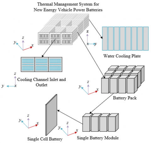
Figure 1 displays two cooling methods for new energy vehicle power battery packs. This paper builds upon common thermal management structures such as air cooling and liquid cooling in the thermal management system of new energy vehicle power batteries. It addresses common thermal issues during battery charging and discharging, such as uneven temperature rise, local overheating, and thermal runaway, by constructing accurate models of power battery heat generation and dissipation. It provides a thermodynamic analysis method that comprehensively considers battery thermal characteristics, environmental factors, and operational states. This method can more finely simulate and predict the temperature distribution and thermal response of batteries in actual operation. Such models are of significant research value for optimizing thermal management system design, achieving efficient heat dissipation, extending battery life, and ensuring safe vehicle operation.
Specifically, the temperature field distribution model of power batteries is built using Comsol Multiphysics, a multi-field physics coupling simulation software. This model integrates the complex heat transfer processes of heat generation, conduction, convection, and radiation of new energy vehicle power batteries in actual operation. Focusing on the battery temperature difference and maximum temperature, two key performance indicators, the study explores the impact of different battery pack arrangements and cell spacing on thermal management efficiency. The model construction ranges from the thermal production of a single battery cell to the heat dissipation of the entire battery pack, conducting a sensitivity analysis on the internal temperature uniformity and peak temperature of the battery pack through parametric design variables, such as cell spacing and arrangement structure. The aim is to reveal the optimal battery pack configuration scheme for achieving low temperature difference and high heat dissipation efficiency. This will guide the actual design of thermal management systems, enhancing the use stability and safety of the entire battery pack.
Figure 1. Two cooling methods for new energy vehicle power battery packs
2.1 Geometric model
In the construction process of the geometric model, special attention is given to the size, arrangement, and material properties of the batteries, and how these factors influence the cooling efficiency and temperature distribution. In this study, the Comsol Multiphysics software is used to build a three-dimensional geometric model of the new energy vehicle power battery and simulate its cooling system. The model design takes into account the actual composition of the battery pack, which consists of 15 cells (3*5) per battery module. To reduce computational load without affecting the accuracy of the simulation results, a single battery module is selected as the study object, assuming that all modules in the cooling system have the same layout and cooling structure. Specifically, each battery pack contains 5 square lithium iron phosphate single cells, which are paralleled in a specific manner to form an energy system.
To address the match between heat generation and cooling capacity of the battery pack under operational conditions, ensuring that the battery can maintain a safe and efficient temperature range under actual operating conditions, this paper calculates the total capacity of the battery pack while constructing the geometric model of the new energy vehicle power battery. The calculation of total capacity reflects the energy conversion efficiency and thermal effects of the battery pack during charging and discharging processes, which is fundamental to understanding the thermal behavior of the battery pack and designing the thermal management system. Assuming power is represented by O, battery pack capacity by Q, the direct current voltage across the battery by I, the number of batteries in the battery pack by v, the discharge time by s, and the capacity of a single cell by w, the calculation formula is provided below.
$v=\frac{\frac{O}{I} \cdot s}{w}=\frac{q}{I w}$ (1)
To address the issues of uniform heat dissipation and coolant flow efficiency in thermal management, this paper thoroughly considers the inline and staggered arrangements of batteries when constructing the geometric model of the new energy vehicle power battery. The inline arrangement may promote more uniform air flow, simplify the flow channel design, and help achieve relatively uniform cooling effects, but it may have local hot spot issues. On the other hand, the staggered arrangement, through its irregular layout, may enhance the turbulence effect, improving heat exchange efficiency, especially in cases with small battery gaps or high thermal loads. It helps break the laminar state of the fluid and improve heat dissipation performance. The basic principle of battery arrangement design in this paper is to ensure as uniform a heat distribution as possible in the battery pack during operation, while promoting efficient heat exchange. This involves considering the mechanisms of heat conduction, convection, and radiation between batteries, allowing the cooling medium to effectively remove heat from the battery surface, prevent local overheating, reduce the stress caused by temperature differences, extend battery life, and enhance the overall energy efficiency of the vehicle. The design must balance the compact layout of the battery module to optimize space utilization, while ensuring sufficient cooling channels for effective heat dissipation. Figure 2 displays the assembly model of the new energy vehicle power battery system.
Figure 2. Assembly model of new energy vehicle power battery system
2.2 Heat generation model
The heat generation model of the new energy vehicle power battery constructed in this paper is based on the heat generation mechanism and heat propagation behavior during the battery charging and discharging process. Firstly, the model considers the main components inside the battery, including the positive and negative current collectors, active materials of the anode and cathode, and the separator, with each material's thermal properties and geometric structure taken into account to ensure accurate simulation of internal heat sources. The physical properties of aluminum foil as the positive electrode current collector, copper foil as the negative electrode current collector, lithium iron phosphate as the positive electrode active material, graphite as the negative electrode active material, and LiPF6 as the electrolyte, such as specific heat capacity and thermal conductivity, are used to calculate the Joule heat caused by electrochemical reactions and internal resistance, as well as the heat generated by interface reactions during the anode and cathode reactions. Secondly, specific working conditions, such as ambient temperature, charge/discharge rates, and charge/discharge cycles, are set, and the model simulates actual working environments and operating modes through these conditions. Based on this, the model predicts the thermal behavior and temperature distribution of the entire battery using thermodynamic equations of heat conduction and convection, according to the heat generation rate of single-layer electrode pairs during the battery charge/discharge cycle. Finally, by simplifying the complex internal heat transfer process, the model can output the average temperature distribution of the battery, revealing the three-dimensional temperature field inside the battery.
2.3 Laminar model
This paper analyzes the flow and heat transfer phenomena of the laminar model of new energy vehicle power batteries through numerical simulations using the Computational Fluid Dynamics (CFD) method.
(1) Stage of Mathematical Modelling
When analyzing the flow and heat transfer phenomena of the laminar model of new energy vehicle power batteries, it is necessary to establish an appropriate mathematical model first to describe the physical phenomena inside the battery. This step is foundational to the research, including the continuity equation to ensure mass conservation, the momentum equation to depict fluid motion, and the energy equation to track heat transfer. These equations collectively constitute the basic control equation set describing the internal flow and heat conduction behavior in the BTMS. The constructed model needs to accurately capture the heat generated during the battery charging and discharging process and its distribution inside the battery, while also considering the battery's geometric structure and the characteristics of the materials used.
(2) Stage of Solving Control Equations
Since the established control equations are usually a set of nonlinear partial differential equations, direct solving is quite complex. Therefore, the finite volume method is adopted for numerical solving. The finite volume method involves integrating over the discrete small volume elements of the battery, converting partial differential equations into algebraic equations, thus applying conservation laws on each control volume. During the solving process, the model needs to be iterated until the convergence criteria are met, thereby obtaining an approximate solution for the internal flow and heat transfer of the battery.
(3) Stage of Meshing and Setting Calculation Conditions
The final step is to mesh the entire physical field and set corresponding initial and boundary conditions for calculation. That is, the battery model is divided into a finite number of small areas or control volumes, in order to solve the control equations in these areas. After mesh division, reasonable initial and boundary conditions are set, such as ambient temperature, charge/discharge rates, etc., reflecting the actual state of the battery during actual operation. In the numerical simulation process, by iteratively calculating, the flow velocity and temperature distribution on each control volume are continuously updated until the entire system reaches a steady state or the transient behavior in the battery thermal management process is simulated.
In the numerical simulation of the new energy vehicle power battery, to capture the flow field and temperature distribution in the BTMS in detail, the incompressible fluid assumption simplifies the calculation of the coolant's velocity field since the coolant flow speed in the cooling system is not too high; then, the Reynolds-averaged Navier-Stokes equations are used to describe fluid motion, combining the continuity equation and momentum conservation equation to solve the flow field velocity distribution; the k-ε turbulence model is introduced to simulate and solve turbulence flow problems, describing the turbulence kinetic energy (k) and dissipation rate (ε) through two transport equations, providing a closure relationship for the turbulent viscosity effects; finally, these fluid dynamics equations are coupled with the battery's heat conduction equation, forming a complete set of control equations for numerical simulation analysis of the fluid flow characteristics in the BTMS and their interaction with the thermal characteristics of the battery pack. Assuming the Reynolds-averaged velocity components are represented by iu and ik, Reynolds-averaged pressure by O, coolant density by ϑ, turbulence kinetic energy and its dissipation rate by j and γ, molecular dynamic viscosity coefficient and turbulent dynamic viscosity coefficient by ω and ωS, respectively. The following expressions give the control equation set:
$\frac{\partial i_u}{\partial a_u}=0$ (2)
$\vartheta i_k=\frac{\partial i_u}{\partial a_k}=-\frac{\partial o}{\partial a_u}+\frac{\partial}{\partial a_k}\left[\left(\omega+\omega_s\right) \frac{\partial i_u}{\partial a_k}\right]$ (3)
$\vartheta i_k \frac{\partial j}{\partial a_k}=\frac{\partial}{\partial a_k}\left[\left(\omega+\frac{\omega_S}{\delta_j}\right) \frac{\partial j}{\partial a_k}\right]+\frac{\omega}{2}\left(\frac{\partial \omega_u}{\partial a_k}+\frac{\partial i_k}{\partial a_u}\right)^2-\vartheta \gamma$ (4)
$\vartheta i_k \frac{\partial j}{\partial a_k}=\frac{\partial}{\partial a_k}\left[\left(\omega+\frac{\omega_S}{\delta_\gamma}\right) \frac{\partial \gamma}{\partial a_k}\right]+Z_1 \frac{\omega_s}{2}\left(\frac{\partial i_u}{\partial a_k}+\frac{\partial i_k}{\partial a_u}\right)^2 \frac{\gamma}{j}-Z_2 \vartheta \frac{\gamma^2}{j}$ (5)
This paper further constructs the heat generation and dissipation control equations for the thermal management system of new energy vehicle power battery packs. By accurately simulating the heat generation and transmission during battery operation, it helps identify key areas of heat accumulation and the paths of heat flow, providing theoretical guidance for designing efficient heat dissipation structures. Figure 3 gives a structural diagram of the thermal management system for new energy vehicle power battery packs.
3.1 Thermal management system optimization design based on battery heat generation mechanism
The heat generated by the battery pack of new energy vehicles during the discharge process mainly consists of four parts. Assume that the heat from chemical reactions is represented by Wz, Joule heat by Wk, heat from side reactions by Wt, and polarization heat by Wo. The following formula gives the total heat generation Ψs of the battery:
$W_s=W_z+W_k+W_t+W_o$ (6)
Chemical reaction heat is the heat released by the positive and negative electrode materials during electrochemical reactions in the discharge process of the power battery, directly related to the battery's energy conversion efficiency and the reactivity of the electrochemical reaction. Battery chemical reaction heat is influenced by battery materials, design, and discharge rate, and is particularly significant during continuous high-load discharge or battery degradation. The thermal management system needs to effectively monitor and regulate chemical reaction heat to prevent overheating that leads to performance degradation or safety issues. The principle of constructing the control equation for chemical reaction heat is mainly based on the electrochemical reaction kinetics of the battery. This equation often involves the Butler-Volmer equation to describe the electrode reaction rate, which is proportional to the current density. Assume the number of batteries is represented by v, the mass of the positive and negative electrodes by l, the total chemical reaction heat generated by the battery by W, the magnitude of the charging and discharging current by U, the molar mass by L, and the Faraday constant by D. The following formula calculates the chemical reaction heat Wz:
$W_z=\frac{v \cdot l \cdot W \cdot U}{L \cdot D}$ (7)
Joule heat, also known as Ohmic heat, is the heat generated when the internal current of the battery passes through resistance. This amount of heat is directly proportional to the square of the internal resistance and current of the battery, meaning that Joule heat significantly increases during high current discharge or when the internal resistance of the battery increases. The generation of Joule heat is inevitable, thus the thermal management system needs to effectively dissipate this heat to maintain the battery temperature within a safe and efficient working range. The construction of the control equation for Joule heat relies on Joule's law, where the internal resistance of the battery and the current passing through the battery are key variables. This equation requires the integration of the battery's internal structure to determine resistance values, such as the type and thickness of electrode materials, the conductivity of the electrolyte, etc. Assume the discharge current is represented by Uf, and the internal resistance of the battery by Ee. The following formula provides the calculation formula for Joule heat Wk:
$W_k=U_f^2 \cdot E_r$ (8)
Figure 3. Structural diagram of the thermal management system for new energy vehicle power battery packs
Heat from side reactions primarily originates from non-ideal chemical reactions during the battery charging and discharging process, such as the decomposition of electrolytes and side reactions of active materials. This type of heat is usually more pronounced in situations of battery overcharging, over-discharging, or operating under extreme temperature conditions. The generation of heat from side reactions often leads to reduced battery efficiency and shortened lifespan, hence the thermal management system needs to limit these side reactions or promptly transfer this heat out of the battery pack. The control equation for heat from side reactions is generally based on the kinetics of the battery's side reactions. The generation of heat from side reactions is often related to the usage and maintenance condition of the battery, such as overcharging, over-discharging, or improper temperature control, all of which can exacerbate side reactions. In the mathematical model, the heat generated by side reactions can be estimated through experimentally determined side reaction rates and related thermochemical coefficients.
Polarization heat originates from the loss of potential during the internal charge transfer process of the battery, including electrode polarization and concentration polarization. Polarization heat is closely related to the internal structure of the battery, such as the properties of the electrode materials, electrolyte, and separator, as well as the operating state of the battery. With an increase in the number of battery cycles, polarization phenomena may intensify, leading to the generation of more polarization heat. To control polarization heat, the thermal management system needs to ensure uniformity inside the battery, reduce polarization phenomena, and prevent excessive temperatures through effective heat dissipation. The control equation for polarization heat reflects the relationship between battery polarization phenomena and heat generation. The mathematical description of polarization heat can characterize electrochemical polarization through the Tafel equation, while concentration polarization is usually described by the Fick's law.
To achieve optimized design of the thermal management system for new energy vehicle power batteries, the first thing is to adjust the battery's operating state and charging/discharging strategies in conjunction with the control equation for chemical reaction heat to reduce heat generation. Secondly, the internal structure and materials of the battery should be optimized using the control equation for Joule heat to lower internal resistance and reduce the heat generated by current flow. Third, identify and minimize unavoidable side reactions through the equation for heat from side reactions, optimizing the battery's usage and maintenance program. Finally, for polarization heat, design efficient electrodes and uniform electrolyte distribution to reduce the degree of polarization during battery operation. Integrating these strategies, and through experimental validation and model simulation, ensures that the battery pack can maintain the optimal temperature range under various working conditions, extending its lifespan and maintaining optimal performance. This paper simulates the cooling of new energy vehicle power battery packs based on the classical battery heat generation model to analyze battery heat generation. Assuming the heat generation rate of a single battery is represented by w, the operating current of the battery by U, the operating voltage of the battery by R, the open-circuit voltage of the battery by R0, the thermodynamic temperature of the battery by S, and the temperature coefficient by dE0/dS, with Joule heat and reversible reaction heat represented by R-R0 and SdE0/dS. The following formula calculates the heat generation rate:
$w=\frac{U}{N_y}\left[\left(R-R_0\right)+S \frac{d R_0}{d S}\right]$ (9)
If considering only the Joule heat, which is the most significant source of heat generation in the battery, and assuming the internal resistance of the battery is represented by Ey, then the above formula can be simplified as:
$w=\frac{U}{N_y}\left(R-R_0\right)=\frac{U^2 E_y}{N_y}$ (10)
3.2 Thermal management system optimization design based on heat transfer analysis of the cooling system
This paper constructs the conduction equation of the cooling system based on Fourier's law. This law states that the heat transfer within a material is directly proportional to the temperature gradient and is also related to the material's thermal conductivity. In the design of the battery pack cooling system, this means that the thermal conductivity of the battery pack, the silicone pad, the cooling plate, and their contact thermal resistance directly affect the efficiency of heat conduction. Therefore, establishing the conduction equation requires accurately assessing the thermal conductivity of each material and the thermal resistance at the contact surfaces to calculate the heat flow from the battery cell through the silicone pad to the cooling plate and then to the cooling channel.
Assuming the density, specific heat capacity, thermal conductivity, and temperature gradient of the material are represented by ϑ, zo, j, and △S, and the heat generation rate per unit volume of a single battery is represented by w. The following formula gives the conduction equation of the cooling system:
$\frac{\partial}{\partial S}\left(\vartheta z_o S\right)=\nabla \cdot(j \nabla S)+w$ (11)
The convective heat transfer equation between the coolant and cooling channels is based on Newton's law of cooling, which describes the heat exchange between the coolant and the cooling channel walls. The heat transfer is directly proportional to the convective heat transfer coefficient of the fluid, the temperature difference between the fluid and the solid surface, and the contact surface area. In the BTMS, constructing the convective heat transfer equation requires considering the flow properties of the coolant, such as viscosity and density, the design of the cooling channels including size, shape, surface roughness, and the temperature distribution under operating conditions. The convective heat transfer equation between the coolant and cooling channels includes three main equations, namely the mass conservation equation, momentum conservation equation, and energy conservation equation as shown below. Assuming the density, specific heat capacity, thermal conductivity, and temperature of the coolant are represented by ϑ1, zo1, j1, and △S1, the flow velocity of the coolant by N, and the static pressure by O, the expressions are:
$\frac{\partial \vartheta_1}{\partial s}+\nabla \cdot\left(\vartheta_1 \vec{n}\right)=0$ (12)
$\frac{\partial}{\partial S}\left(\vartheta_1 \vec{n}\right)+\nabla \cdot\left(\vartheta_1 \vec{n} \vec{n}\right)=-\nabla O$ (13)
$\frac{\partial}{\partial S}\left(\vartheta_1 z_{o 1} S_1\right)+\nabla \cdot\left(\vartheta_1 z_{o 1} \vec{n} S_1\right)=\nabla \cdot\left(j_1 \nabla S_1\right)$ (14)
Based on the conduction equation of the cooling system, this paper finely adjusts the material selection and structural layout between the battery pack and the silicone pad, and between the silicone pad and the cooling plate, to minimize interface thermal resistance, ensuring that the heat generated by the battery can be efficiently transferred to the cooling plate. Simultaneously, in conjunction with the convective heat transfer equation between the coolant and cooling channels, optimize the flow path of the coolant, increase the flow velocity of the coolant, select suitable coolant properties, and design reasonable cooling channel shapes and surface treatments to maximize convective heat transfer efficiency. Together, these equations can guide the optimization of the BTMS, ensuring efficient heat dissipation under various operating conditions, maintaining an appropriate working temperature, thereby enhancing battery performance, extending lifespan, and ensuring safe operation.
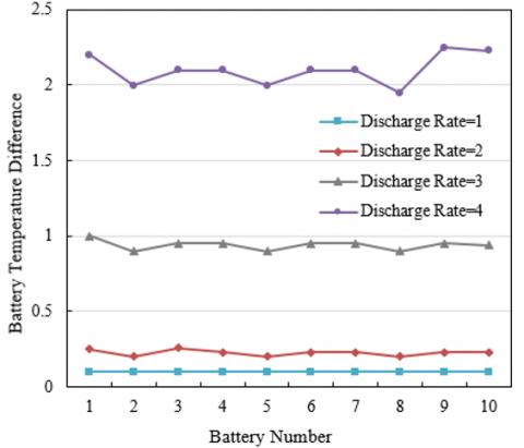
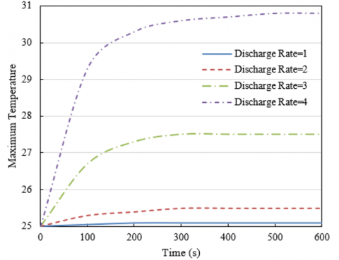
Based on Figures 4 and 5, an analysis of the temperature difference and maximum temperature change of battery packs with side-mounted water cooling plates under different discharge rates can be conducted, along with the implications of these data for the optimization of the thermal management system. Figure 4 indicates that the internal temperature difference within the battery pack increases with the discharge rate. At a discharge rate of 1C, the temperature difference across all batteries remains at 0.1°C, indicating a relatively uniform temperature distribution at low discharge rates. However, as the discharge rate increases to 2C, the temperature difference begins to increase but remains below 0.25°C, suggesting a relatively balanced heat generation and removal. But at discharge rates of 3C and 4C, the temperature difference significantly increases, reaching up to 2.25°C, indicating uneven temperature distribution within the battery pack at high discharge rates, necessitating more effective thermal management strategies to ensure thermal stability of the battery pack. According to Figure 5, the maximum temperature of the battery pack also significantly increases with the discharge rate. At a discharge rate of 1C, the maximum temperature increases from 25°C to 25.1°C within 600 seconds, a minor increase. However, at a discharge rate of 4C, the maximum temperature increases from 25°C to 30.8°C within the same timeframe, a substantial increase, indicating rapid heat accumulation and a quick rise in battery temperature at high discharge rates. It can be concluded that at higher discharge rates, both the temperature difference and maximum temperature change significantly increase, posing challenges to the long-term stability and safety of the battery. While thermal management requirements are not demanding at low discharge rates, more effective cooling measures are needed at high discharge rates.
To accommodate thermal management needs at different discharge rates, the following optimization strategies for the power BTMS are proposed: 1) Maintain the existing water-cooling plate system, as data shows temperature differences and changes are within a controllable range at low discharge rates. 2) Optimize water flow design by increasing the flow rate of the coolant or adjusting the layout of the cooling channels to enhance cooling effects. 3) Introduce phase change materials (PCM) or enhanced cooling systems, such as using larger heat sinks, increasing the efficiency of cooling fans, or using higher performance coolants.
Table 1 shows the temperature difference comparison of battery packs under different discharge rates and cooling structures (bottom, side, and combination). The data indicate that bottom cooling results in a significant temperature difference at high discharge rates, for instance, reaching an astonishing 51.23°C for battery number 4, demonstrating the inability of bottom cooling structures to effectively control temperature at high discharge rates. Side cooling significantly reduces the temperature difference across all discharge rates, with the maximum temperature difference being only 2.41°C (battery number 7), showing that side cooling is significantly superior in thermal management compared to bottom cooling. Combination cooling further reduces the temperature difference, especially at high discharge rates, although slightly higher than side cooling, it is much lower than bottom cooling, showcasing the superiority of the combination cooling structure. This validates that the proposed thermodynamic model can accurately reflect the impact of different cooling structures and discharge rates on the temperature difference of the battery pack, thereby verifying the model's practicality for predicting and optimizing the thermal management system of power batteries.
Based on the above analysis, the following optimization strategies are proposed: 1) For low discharge rates (e.g., 1-2C): Since the temperature difference is not significant, cost-effective cooling solutions such as a single bottom or side cooling structure can be selected. 2) For medium discharge rates (e.g., 3-4C): While side cooling performs quite well, a combination cooling structure can be adopted to further reduce the temperature difference. 3) For high discharge rates (5C and above): Due to the increased temperature difference at high discharge rates, more advanced combination cooling structures should be utilized, along with considering the introduction of real-time temperature monitoring and dynamic cooling adjustment systems to ensure uniform temperature distribution.
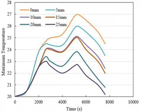
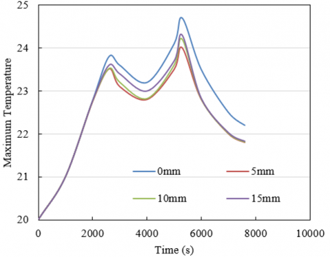
According to Figure 6, when the vertical spacing increases from 0mm to 25mm, the maximum temperature of the battery pack shows an overall downward trend. Especially during the high-temperature phase (2600 seconds to 7600 seconds), a larger spacing can effectively reduce the peak temperature of the battery. At a 0mm spacing, the temperature of the battery pack rises the fastest and reaches the highest temperature, indicating poor heat dissipation conditions when there is no gap between the batteries. When the spacing increases to 25mm, the temperature of the battery pack is the lowest at any given time point, demonstrating that appropriately increasing the vertical spacing can significantly improve cooling performance. As shown in Figure 7, the maximum temperature of the battery pack also shows an overall downward trend with an increase in horizontal spacing, although this trend is not as pronounced as in the vertical direction. Even at a 0mm spacing, the temperature rise and peak temperature in the horizontal direction are lower than those in the vertical direction at a 0mm spacing, due to more effective natural convection and radiation cooling in the horizontal direction. At a 15mm horizontal spacing, the temperature rise rate and peak temperature reach a relatively optimal balance point. By accurately simulating the temperature rise behavior of power battery packs at different spacings, this thermodynamic model effectively reveals the direct relationship between battery cooling performance and spacing size, again proving its application value in the design and optimization of BTMSs.
Figure 4. Temperature difference of battery packs with side-mounted water cooling plates at different discharge rates
Figure 5. Maximum temperature change of battery packs with side-mounted water cooling plates at different discharge rates
Table 1. Comparison of temperature differences in battery packs under different discharge rates and cooling structures
|
Battery Number |
1 |
2 |
3 |
4 |
||||||||
|
Bottom |
Side |
Combination |
Bottom |
Side |
Combination |
Bottom |
Side |
Combination |
Bottom |
Side |
Combination |
|
|
1 |
1.45 |
0.08 |
0.11 |
5.82 |
0.23 |
0.48 |
22.12 |
0.98 |
2.2 |
51.23 |
2.21 |
4.23 |
|
2 |
1.45 |
0.07 |
0.11 |
5.82 |
0.2 |
0.46 |
22.25 |
0.88 |
2.12 |
52.36 |
2.11 |
4.21 |
|
3 |
1.45 |
0.07 |
0.11 |
5.83 |
0.23 |
0.46 |
22.36 |
0.92 |
2.13 |
51.24 |
2.14 |
4.231 |
|
4 |
1.45 |
0.09 |
0.11 |
5.84 |
0.22 |
0.46 |
22.14 |
0.92 |
2.14 |
52.64 |
2.13 |
4.23 |
|
5 |
1.46 |
0.08 |
0.11 |
5.85 |
0.21 |
0.46 |
22.68 |
0.87 |
2.14 |
51.89 |
2.15 |
4.25 |
|
6 |
1.47 |
0.09 |
0.11 |
5.85 |
0.23 |
0.45 |
22.36 |
0.93 |
2.13 |
52.31 |
2.21 |
4.26 |
|
7 |
1.45 |
0.09 |
0.11 |
5.84 |
0.23 |
0.46 |
22.45 |
0.93 |
2.11 |
51.48 |
2.41 |
4.25 |
|
8 |
1.45 |
0.1 |
0.11 |
5.84 |
0.21 |
0.46 |
22.15 |
0.88 |
2.12 |
52.36 |
1.98 |
4.21 |
|
9 |
1.45 |
0.09 |
0.11 |
5.81 |
0.23 |
0.46 |
22.16 |
0.98 |
2.12 |
51.23 |
2.15 |
4.28 |
|
10 |
1.44 |
0.09 |
0.12 |
5.82 |
0.23 |
0.5 |
22.98 |
0.95 |
2.14 |
51.27 |
2.16 |
4.29 |
Figure 6. Maximum temperature distribution of battery packs with different vertical spacings
Figure 7. Maximum temperature distribution of battery packs with different horizontal spacings
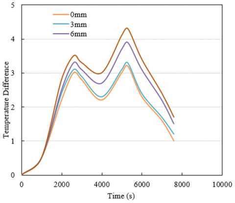
Figure 8. Temperature difference distribution in battery packs with different staggered spacings
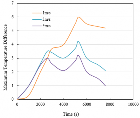
Figure 9. Maximum temperature difference in battery packs at different flow rates
Based on the above analysis, the following optimization strategies are provided: 1) Increase vertical spacing: To improve cooling efficiency, the vertical spacing between battery components can be increased, especially in applications where the battery operates at high temperatures or for extended periods, such as a 25mm spacing can significantly reduce the maximum temperature. 2) Consider moderate horizontal spacing: Increasing horizontal spacing also aids in temperature control, but considering space utilization, a moderate spacing, like 15mm, can be chosen to achieve a balance between cooling effect and space efficiency. 3) Optimize the flow path of cooling fluid: In conjunction with increased spacing, optimizing the flow path of the cooling fluid can enhance cooling efficiency, especially in the high-temperature areas of the battery pack.
Figure 8 describes the internal temperature difference distribution in battery packs under different staggered spacings. The data indicate that with an increase in staggered spacing, the maximum temperature difference within the battery pack generally shows an increasing trend. The temperature difference is lowest at a 0mm spacing and highest at a 9mm spacing. From the start (0 seconds) to 1000 seconds, the temperature difference increase is minimal under all spacing conditions, due to a more uniform internal temperature distribution within the battery pack. From 1000 seconds to 7600 seconds, the increase in temperature difference is more significant, especially at larger spacings (e.g., 6mm and 9mm), indicating that a larger spacing leads to an uneven internal temperature distribution during prolonged operation. Among all tested spacings, starting from 3000 seconds, the rate of increase in temperature difference for battery packs with larger spacings surpasses that of battery packs with smaller spacings, particularly at a 9mm spacing. The predictive results of this thermodynamic model accurately reflect the impact of staggered spacing on the internal temperature difference distribution within the battery pack, thereby confirming its critical role in evaluating and optimizing the design of power BTMSs.
Based on the above analysis, the following optimization strategies are proposed:
(1) Spacing selection: Choose an optimal staggered spacing to balance the internal temperature uniformity and cooling capability of the battery pack. According to data, smaller spacings (e.g., 3mm) maintain a lower temperature difference initially, but long-term temperature difference control should be considered.
(2) Enhance internal air flow: Enhance internal air flow through design optimization or forced air flow devices such as auxiliary fans to improve temperature difference control at larger spacings.
(3) Temperature monitoring and control: Implement real-time temperature monitoring and dynamic control systems to adjust the internal temperature difference within the battery pack, especially at larger staggered spacings.
(4) Optimize cooling structure: Optimize the cooling structure of the battery pack, such as using heat pipes, thermal diffusion plates, or other efficient cooling materials, to improve cooling efficiency.
Figure 9 shows the changes in the maximum temperature difference of battery packs under different coolant flow rates (1m/s, 3m/s, 5m/s). The figure indicates that at a low flow rate (1m/s), the temperature difference grows relatively slowly at the initial stage. However, as time progresses, the maximum temperature difference significantly increases, especially between 3000 seconds to 5300 seconds, reaching a maximum of 6°C, after which the temperature difference decreases but still remains at a high level overall. This suggests that low flow rates are effective initially, but insufficient for cooling over longer durations. At a medium flow rate (3m/s), this flow rate performs the best among all tested. The maximum temperature difference peaks at 3.5°C around 2000 seconds, then gradually decreases. This demonstrates that at this flow rate, the cooling system can effectively control the temperature of the battery pack, providing more stable and sustained cooling performance. At a high flow rate (5m/s), although the temperature difference quickly increases at the initial stage, it significantly decreases over time, indicating more pronounced cooling effects at high flow rates, especially after prolonged operation. Overall, a medium flow rate (3m/s) offers the most balanced and effective control of battery pack temperature difference. While high flow rates can significantly reduce temperature differences after long durations, but they have energy efficiency concerns.
Based on the analysis, the following optimization strategies are proposed: 1) Flow rate optimization: Set a medium and adjustable coolant flow rate to meet the cooling needs of the battery under different operating conditions. 2) Flow rate control system: Introduce an intelligent control system that dynamically adjusts the coolant flow rate based on real-time temperature difference data of the battery pack to achieve optimal cooling effects. 3) Energy efficiency evaluation: Assess the energy efficiency of the cooling system to ensure that while achieving the required cooling effects, the system's energy consumption is kept to a minimum. 4) Cooling structure optimization: Research and develop efficient cooling structures, such as improving cooling channel design, utilizing heat pipes or phase change materials to enhance thermal conduction.
This paper focuses on the construction of thermodynamic models for new energy vehicle power battery packs, analysis of heat generation mechanisms, and evaluation and optimization design of thermal management systems. The research aim is to provide efficient and safe thermal management system optimization designs for battery pack thermal characteristics and their complex working environments through in-depth analysis of thermodynamic behavior during battery operation.
Experimental analyses of temperature differences and maximum temperature changes in battery packs with side-mounted water-cooling plates under different discharge rates reveal that increased discharge rates lead to increased heat generation, imposing higher requirements on the thermal management system. Comparisons of temperature differences in battery packs under different discharge rates and cooling structures show that optimizing cooling structures can significantly improve temperature uniformity. Analyses of the highest temperature distribution in battery packs under different vertical and horizontal spacings provide important data for battery stacking design. Studies on temperature difference distribution in battery packs with different staggered spacings determine the optimal staggered spacing for the best cooling effects. Experimental research on the maximum temperature difference in battery packs under different coolant flow rates establishes the relationship between coolant flow rate and battery pack temperature difference, identifying the optimal balance point between cooling effect and energy efficiency at medium flow rates.
Through precise thermodynamic model construction and in-depth experimental analysis, this study demonstrates that optimizing thermal management systems can significantly enhance the energy efficiency and safety performance of power batteries. By carefully adjusting cooling strategies and designing cooling structures, the temperature difference and maximum temperature under different operating states can be effectively controlled, ensuring stable operation of the battery pack within a safe range and improving overall vehicle energy efficiency. Future work could focus on developing more intelligent thermal management systems, using machine learning algorithms to dynamically adjust cooling strategies based on real-time data. Promoting the integrated design of thermal management systems and battery management systems could reduce system weight and cost and improve response times.
[1] Zheng, Y.T., Zhang, T., Liu, G.H., Li, Y., Cheng, C., Xu, L.X., Cheng, X.Z., Cao, X.D. (2022). Research of new energy vehicles user portrait and vehicle-owner matching model based on multi-source big data. In Signal and Information Processing, Networking and Computers: Proceedings of the 8th International Conference on Signal and Information Processing, Networking and Computers (ICSINC), Springer, Singapore, pp. 1440-1448. https://doi.org/10.1007/978-981-19-3387-5_171
[2] Tang, X.R., Wang, B. (2023). The development and industry risks of new energy vehicles in China. In International Conference on Statistics, Data Science, and Computational Intelligence (CSDSCI 2022), Qingdao, China, 12510: 16-21. https://doi.org/10.1117/12.2656905
[3] Zhang, Z. (2023). Analysis of cooling technology of power battery of new energy vehicles. In Journal of Physics: Conference Series, 2649(1): 012004. https://doi.org/10.1088/1742-6596/2649/1/012004
[4] Zhou, X.J., Li, J.Z., Li, F., Deng, X.D. (2023). Recycling supply chain mode of new energy vehicle power battery based on Blockchain technology. Computer Integrated Manufacturing System, 29(4): 1386-1398. https://doi.org/10.13196/j.cims.2023.04.029
[5] Ruan, G., Yu, C., Hu, X., Hua, J. (2021). Simulation and optimization of a new energy vehicle power battery pack structure. Journal of Theoretical and Applied Mechanics, 59(4): 565-578.
[6] Ramadan, Z., Abbas, S., Park, C.W. (2023). Thermal management analysis of simulative power batteries using phase change material and flat heat pipe. Heat and Mass Transfer, 59(3): 427-437. https://doi.org/10.1007/s00231-022-03257-4
[7] Yu, H., Zhang, H., Shi, J., Liu, S., Yi, Z., Xu, S., Wang, X. (2023). Thermal parameters of cylindrical power batteries: Quasi-steady state heat guarding measurement and thermal management strategies. Applied Thermal Engineering, 120959. https://doi.org/10.1016/j.applthermaleng.2023.120959
[8] Zhang, J., Shao, D., Jiang, L., Zhang, G., Wu, H., Day, R., Jiang, W. (2022). Advanced thermal management system driven by phase change materials for power lithium-ion batteries: A review. Renewable and Sustainable Energy Reviews, 159: 112207. https://doi.org/10.1016/j.rser.2022.112207
[9] Wang, W., Li, C., Zeng, X., Chen, J., Sun, R. (2022). Application of polymer-based phase change materials in thermal safety management of power batteries. Journal of Energy Storage, 55: 105646. https://doi.org/10.1016/j.est.2022.105646
[10] Yue, Q.L., He, C.X., Wu, M.C., Zhao, T.S. (2021). Advances in thermal management systems for next-generation power batteries. International Journal of Heat and Mass Transfer, 181: 121853. https://doi.org/10.1016/j.ijheatmasstransfer.2021.121853
[11] Liu, Y., Zheng, R.W., Li, J. (2022). High latent heat phase change materials (PCMs) with low melting temperature for thermal management and storage of electronic devices and power batteries: Critical review. Renewable and Sustainable Energy Reviews, 168: 112783. https://doi.org/10.1016/j.rser.2022.112783
[12] Wang, Z., Du, C. (2021). A comprehensive review on thermal management systems for power lithium-ion batteries. Renewable and Sustainable Energy Reviews, 139: 110685. https://doi.org/10.1016/j.rser.2020.110685
[13] Huang, Y., Tang, Y., Yuan, W., Fang, G., Yang, Y., Zhang, X.Q., Wu, Y.P., Yuan, Y.H., Wang, C., Li, J. (2021). Challenges and recent progress in thermal management with heat pipes for lithium-ion power batteries in electric vehicles. Science China Technological Sciences, 64(5): 919-956. https://doi.org/10.1007/s11431-020-1714-1
[14] Poongavanam, P., Chand, A.A., Tai, V.B., Gupta, Y. M., Kuppusamy, M., Dhanraj, J.A., Velmurugan, K., Rajagopal, R., Ramachandran, T., Prasad, K.A., Chand, S.S., Raj, S. Mamun, K.A. (2023). Annual thermal management of the photovoltaic module to enhance electrical power and efficiency using heat batteries. Energies, 16(10): 4049. https://doi.org/10.3390/en16104049
[15] Jiang, K., Liao, G., Jiaqiang, E., Zhang, F., Chen, J., Leng, E. (2020). Thermal management technology of power lithium-ion batteries based on the phase transition of materials: A review. Journal of Energy Storage, 32: 101816. https://doi.org/10.1016/j.est.2020.101816
[16] Wu, T.T., Hu, Y.X., Liu, X.Q., Wang, C.L.(2021). Effect analysis on thermal management of power batteries utilizing a form-stable silicone grease/composite phase change material. ACS Applied Energy Materials, 4(6): 6233-6244. https://doi.org/10.1021/acsaem.1c00999
[17] Huang, D., Zhang, H.Y., Wang, X.J., Huang, X.H., Dai, H.F. (2021). Experimental investigations on the performance of mini-channel evaporator refrigeration system for thermal management of power batteries. International Journal of Refrigeration, 130: 117-127. https://doi.org/10.1016/j.ijrefrig.2021.05.038
[18] Behi, H., Behi, M., Karimi, D., Jaguemont, J., Ghanbarpour, M., Behnia, M., Berecibar, M., Van Mierlo, J. (2021). Heat pipe air-cooled thermal management system for lithium-ion batteries: High power applications. Applied Thermal Engineering, 183: 116240. https://doi.org/10.1016/j.applthermaleng.2020.116240
[19] Chen, J.W., Kang, S.Y., Huang, Z.H., Wei, K.X., Zhang, B., Zhu, H., Deng, Y.W., Zhang, F., Liao, G. (2019). Effects of different phase change material thermal management strategies on the cooling performance of the power lithium ion batteries: A review. Journal of Power Sources, 442: 227228. https://doi.org/10.1016/j.jpowsour.2019.227228
[20] Xia, Z.G., Li, C., Yu, H., Wang, Z.R. (2023). Experimental study of a passive thermal management system using expanded graphite/polyethylene glycol composite for lithium-ion batteries. Energies, 16(23): 7786. https://doi.org/10.3390/en16237786
[21] He, L., Gu, Z., Zhang, Y., Jing, H., Li, P. (2023). Review on thermal management of lithium-ion batteries for electric vehicles: Advances, challenges, and outlook. Energy & Fuels, 37(7): 4835-4857. https://doi.org/10.1021/acs.energyfuels.2c04243