Mohammed Belaghit*![]() | Rachid Saim
| Rachid Saim![]()
© 2024 The authors. This article is published by IIETA and is licensed under the CC BY 4.0 license (http://creativecommons.org/licenses/by/4.0/).
OPEN ACCESS
In the field of scientific exploration, this study delves into the captivating realm of ground heat exchangers (GHE) by investigating the impact of rectangular protrusions strategically incorporated at the base of these systems. As vital components within geothermal systems, GHEs are responsible for efficiently transferring of thermal energy between the earth and the working fluid. However, through the ingenious integration of rectangular protuberances, the convective heat transfer dynamics within GHEs can be skillfully manipulated, potentially leading to remarkable enhancements in the heat exchange process. The maximum percentage increase in the heat transfer rate reached 23% at a distance of 2,500 meters, emphasizing the importance of strategic positioning of the protrusions. The primary objective of this research endeavor is to comprehensively examine the effects of these protrusions on the extracted temperature of the injected working fluid, thus yielding invaluable insights for optimizing GHE performance and advancing of geothermal energy utilization.
computational fluid dynamics, coefficient of performance, geothermal energy, heat transfer, rectangular protrusion, wellbore heat exchanger
Energy has made a salient change throughout history in human civilization; the demand for it has been increasing according to human development. The latter leads to a terrible drain of fuel, and that also resulted in a rise in carbon dioxide, which caused a threat to the environment [1]. From the standpoint mentioned above, resorting to renewable energies has become necessary as a promising alternative to fossil fuels [2]. Renewable energies are considered unextended exhausting energy, but they are unstable because they are subject to natural and meteorological factors such as solar energy, wind energy, and tides [3]. However, geothermal energy is distinct from the other sorts since the natural factors do not influence it and because it is available all over the world. It is considered as a radical and promising solution to interrupt energy [4], it was first exploited in the twentieth century when its production reached from 6 to 7 GW in 1995. Specialists expect it to reach 17GW in 2023 [5]. According to the International Energy Agency, it will promote to 1400TWh on 2050 [6], and in 2017, thermal energy represented only 2% compared to all other renewable energy sources [5].
The real problem and the biggest challenge are how to dig and exploit this geothermal energy in reality due to the high cost of digging and the difficulty of installing these underground heat exchangers, and from the interest in exploiting abandoned wells [7], as there are about 20 to 30 million abandoned wells in the world. The depth of these wells’ ranges from about 1000 to more than 3000 meters, which qualifies them to be good in the extraction of geothermal energy [8], in addition to that, the maintenance and modification of these wells is an ideal economic solution to reduce the state cost [9] by 50% of the total cost of digging [10]. It also contains physical records and geological studies stored for these companies [2]. From here, the researchers focused on designing and improving ground heat exchangers which include determining the type and appropriate configuration of the ground heat exchanger, in addition, its operating parameters to extract this energy, the most common heat exchangers can be used, which are systems closed-loop and open-loop systems [11]. For the closed-loop, it is in one well and has two different methods: the first is by placing two parallel U-shaped tubes, and the second method is for the tubes concentric. The closed-loop is characterized by reducing the risk of contamination of the injection liquid for example with mercury and methane [8]. As for the open-loop at least two closely spaced wells are required, the first is for injection and the second for extraction, and it is very expensive because of the cost of connecting the two wells, but it has a high extraction capacity [12]. As such, various of technologies have been developed to maximize its potential including the use of a closed double heat exchangers system (DCHE). The benefits of using the DCHE system in GHES were explored in a study by Zhang et al. that the DCHE system can reduce the heat loss in GHES by about 5%, thus increasing energy savings for users. A DCHE system can reduce the amount of water supplied to GHEs by up to 10%, this can also decrease maintenance and operating costs associated with GHEs as less water will be required. These consequences denote that DCHE system might be a vital addition to GHEs, providing improved energy savings and operational efficiency [13]. According to a recent study conducted by Boban et al. [14] on direct heat exchange (DHE) systems, they can provide a high degree of temperature control the stability of other GHES is due to their ability to use independent thermal control, the latter allows them to maintain an equilibrium temperature state.
In recent research by Shi et al. [15], the DHE system works by separating the GHE rings allowing for improved heat transfer and faster response times. Furthermore, the use of DHE system allows the GHE to be designed more compactly. In other words, the required land area makes it more suitable for urban areas. Moreover, direct heat exchange systems also require less maintenance, which contributes more in savings. Hence, exchange systems have become implicit convection increasingly common in GHEs. Scientists Bu et al. [16] have extensively studied the efficiency of geothermal heat exchangers in the SWGH seasonal ground water heat system, and Bu et al. in their paper on renewable energy; they attempted to measure the efficiency of SWGH systems as well as the efficiency of geothermal heat exchangers in their research in 2019. Simulation results showed that at a constant injection water temperature and flow rate, the average annual heat output extracted in tenth heating season decreased by 7.77 compared to the first heating season. DBHE can easily be adjusted by altering the temperature and velocity of the injection water, so that the well spacing should not be less than 100 meters for years of operation to avoid disturbing each other. Meanwhile, well depth effect is analyzed to promote the application SWGH as well. Technology in a contemporary study by Yu et al. talks about the benefits of using the EDBHE system in ground heat exchangers, at the same time, EDBHE system is a type of ground heat exchanger system that uses a closed-loop of tubes filled with a fluid to transfer heat between the ground and building. Numerical simulations have been conducted to verify the performance of EDBHE production for 30 years. The findings showed that the average annual heat production rate in this period of EDBHE is 463.2 KW, equal to 1.27 times compared to DBHE and that the heat production rate and outlet temperature depend mainly on the artificial soil concrete area [17]. The results demonstrated that the energy extracted from EDBHE is 1002.4 KW and 424.45 KW from DBHE equivalent to 2.36 times, as well as the fixed payback period of 3.12 years and 7.17 years for DBHE, which paves the way to expansion and acceleration of EDBHE systems in the future. He and Bu proposed an improved heat exchanger EDBHE using ordinary clay and cement in the preparation of composite fillers [18]. Gharibi et al. [2] carried out a digital study presenting an abandoned well and a source of geothermal heat and used the U-tube shape. They deduced that this source can be used for long periods to produce electricity in particular and other applications. The findings show that the outlet temperature does not change with time, to illustrate, in the case of an entrance temperature of 288.16 K and an entrance speed of 0.03 m/s the outlet temperature reaches 324.734 K per year and for five years of operation, decreases to 324.13 K .In other cases, the energy production reached 48.8KW from one well with a temperature gradient of 31.1 m/s, it is suitable for producing electricity since the insulator is also necessary at the second outlet of the U-tube to maintain the temperature. A. Davis and Michaelides conducted their study using isobutane as the main component of the working fluid in the context of well exploration. They analyzed the effect of isobutane injection pressure at the bottom of the well. In addition to the temperature and geometry of the well, the researcher pointed out the need to take into account well improving steps including improving the well geometry and balancing the injection temperature and pressure in order to increase the efficiency of energy extraction [19]. In research conducted by Hu et al. [5] coaxial shape and after 25 years of operation rate of 10 kg/s and a temperature of 20℃. The production temperature reaches 27.9 and 0.38 MW, this work shows that we can exploit abandoned oil wells to extract geothermal BHE axial energy in the Hilton region. The performance of axial BHE is affected by the temperature that depends on the heat transfer characteristics controlled by the injection temperature, injection rate, and thermal conductivity of the insulating tube. Kujawa et al. [20] explained that the gained energy from the underground exchangers refers to two main factors: the injection temperature and the injection rate as with the decrease in the temperature of the injection liquid entering the pipe. Both the heat output of the geothermal energy inputs and the amount of energy gained increase for larger water flows; the effects are smaller although relatively larger heat flows can be obtained. Nevertheless, the temperatures used are low. Change et al. [9] assert that the double tube heat exchangers are preferred over U-shaped heat exchangers on one hand. On the other hand, the use of triangular protrusion is better inside the pipe because it is installed in the lower part. Whereas, the higher protrusion produces more promising results than the lower one. According to the previous work, using protrusions inside the heat exchangers increases the value of the temperature extracted from the well, and the field is still extensive in t developing protrusion and needs in the future studies to develop them.
Through the above data of our work, we are going to install rectangular protrusions on the bottom of the heat exchanger at different dimensions, starting from the bottom of the well and extracting through them; the best extracted the maximum temperatures. In addition, we will to follow the same process and apply it at maximum amounts of energy obtained and the maximum (COP), which is the ratio of heat transfer rate and pumping power. This research will let us better understand of how to improve the performance of the heat exchanger in the modified well. As a result, we shall obtain the optimal design and operating criteria for the outcroppings. Our findings might be useful in ameliorating these systems so that heat extraction efficiency can be promoted. Therefore, we shall enhance the performance in general.
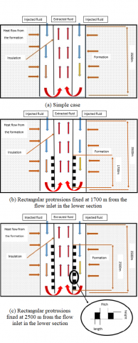
Geometry plays a vital role in the performance of a double pipe closed-loop heat exchanger. Hu et al. [5] developed a model that considers the geometry of such systems to predict their performance accurately. As shown in Figure 1, only two pipes are used in this model, allowing for a more efficient energy exchange between the two fluids. This study will investigate how different geometric parameters affect the thermal performance of this type of heat exchanger. Geothermal fluid flows in a heat exchanger between an inner and outer casing, providing a unique way to generate energy. During this process, the fluid travels downward to the well bottom, where it is heated by the Earth’s internal heat. This hot water is then circulated through a closed-loop system. Heat is transferred from the surrounding rocks to the fluid through conduction and convection. This hot fluid is then channeled up to the surface where it can be used for energy production by understanding how heat is transferred, Insulation plays an important role in preventing heat loss from the higher temperature returning fluid to the colder inflow fluid. This helps to maintain a consistent temperature in the system.
The proposed model is a multilayered system designed to be practical and effective. It consists of several layers, such as rock layers, cement, outer casing, fluid inlet, insulating casing, insulation, inner casing, liquid outlet and protrusion rectangular. Each of these layers has its own purpose and function to deliver the best possible performance. Combining all these elements together into one coherent model can provide an effective way to manage energy production. Table 1 presents the geometric parameters and operating conditions examined in this study, whereas Table 2 provides the material properties. The rectangular protrusions installed along the lower of the wellbore are a great example of how engineering can be used to influence the flow of water, see Figure 1. These protrusions create turbulence in the water by increasing the surface area for heat transfer, this design helps to increase the rate at which heat can be exchanged between the ground and the circulating fluid, increase thermal conductivity, better heat transfer rates, and improve energy efficiency.
Figure 1. Three heat transfer for a closed-loop heat exchanger: (a), (b) and (c)
Table 1. Default parameters for simulation cases
|
Items |
Values |
|
Total depth of well (m) |
3,500 |
|
Outflow Diameter (m) |
0.0662 |
|
Inner Casing Diameter (m) |
0.0862 |
|
Inflow Diameter (m) |
0.1678 |
|
Outer Casing Diameter (m) |
0.1878 |
|
Protrusion Length (m) |
10 |
|
Protrusion Height (m) |
0.14 |
|
Pitch (m) |
30 |
|
Insulation length of the annulus (m) |
1,000 |
|
Temperature Gradient (℃/km) |
38 |
|
Diameter of formation (m) |
280 |
Table 2. Physical parameters of medium
|
Physical Parameters |
Water |
Casing Steel |
Cement |
Insulating Tube |
Form Ation |
|
Density kg/m3 |
998.2 |
7,850 |
2,140 |
1,150 |
2,600 |
|
Thermal capacity J/ (kg. k) |
4,184.4 |
475 |
2,000 |
1,700 |
823.87 |
|
Thermal conductivity W/(m. k) |
0.60 |
44.5 |
0.8 |
0.26 |
2.94 |
3.1 Governing equations
The summary of Table 1 presents the geometrical parameters of the model, Table 2 the thermophysical properties of the material under consideration and the operating conditions applied in this study. By considering these parameters and making certain assumptions, the conservation of energy for the solid domain comprising strata rocks, insulation, pipe, and cement can be expressed as in the studies of Kurnia et al. [7] and Cheng et al. [9] by:
$K \cdot \nabla^2\cdot T=0$ (1)
The equations governing the conservation of mass, momentum, and energy for the working fluid within the wellbore heat exchanger can be expressed as follows:
$\nabla \cdot\left(\rho_f u\right)=0$ (2)
$\nabla \cdot\left(\rho_f u u\right)=\nabla_\sigma+\rho_f \cdot g$ (3)
$\nabla \cdot\left(\rho_f C_{p \cdot f} u T\right)=\nabla \cdot\left(k_f \nabla T\right)$ (4)
The fluid stress tensor, $\sigma$, is defined as:
$\begin{aligned} \sigma & =-p I+\left(\mu_f+\mu_{t . f}\right)\left(\nabla_u+\left(\nabla_u\right)^T\right) +\frac{2}{3} \nabla \cdot\left[\left(\mu_f+\mu_{t . f}\right) \cdot(\nabla \cdot u) I-\rho_f K I\right]\end{aligned}$ (5)
This equation accounts for various factors contributing to the distribution of stress within the fluid, including pressure, viscous effects, and the influence of turbulent flow characteristics such as the turbulent viscosity and kinetic energy.
3.2 Turbulence model
In this investigation, the standard k-ε turbulence model, which is widely employed in engineering, has been chosen as the primary model. This model comprises a system of two equations dedicated to solving for the turbulent kinetic energy k and its rate of dissipation ε, which are closely associated with the turbulent viscosity. The governing equations for the standard k-ε model are expressed as follows [21]:
$\begin{aligned} \frac{\partial}{\partial t}(\rho K)+\nabla \cdot(\rho u K) & =\nabla \cdot\left[\left(\mu+\frac{\mu_t}{\sigma_k}\right) \nabla_k\right] +G_K-\rho \varepsilon\end{aligned}$ (6)
$\begin{aligned} \frac{\partial}{\partial t}(\rho \varepsilon)+\nabla \cdot(\rho u \varepsilon) & =\nabla \cdot\left[\left(\mu+\frac{\mu_t}{\sigma_{\varepsilon}}\right) \nabla \varepsilon\right] +C_{1 \varepsilon} \frac{\varepsilon}{K} G_K-C_{2 \varepsilon} \rho \frac{\varepsilon^2}{K}\end{aligned}$ (7)
The turbulent viscosity $\mu_t$ can be expressed by:
$\mu_t=\rho C_\mu \frac{k^2}{\varepsilon}$ (8)
These equations depict the temporal and spatial variations of the turbulent kinetic energy and its transport within the flow field, considering the effects of turbulent viscosity, production of turbulence, and dissipation.
3.3 Heat transfer performance
The heat transfer rate $\dot{Q}$ of the well can be expressed as in [5]:
$\dot{Q}=\dot{m} c_p\left(T_{ {out }}-T_{i n j}\right)$ (9)
This equation quantifies the amount of heat transferred per unit time in the well, considering the mass flow rate of the fluid, its specific heat capacity, and the temperature difference between the outlet and injection points.
The evaluation of heat transfer performance is carried out using the Coefficient of Performance COP , which is defined as [4]:
$C O P=\frac{\dot{Q}}{W_{p u m p}}$ (10)
The pumping power Wpump necessary to propel the fluid flow through the well is calculated as [21]:
$W_{p u m p}=\frac{1}{\eta_{p u m p}} \dot{V} \Delta P$ (11)
The outcomes of the study are presented and assessed by analyzing the percentage increase in heat transfer rate, the in the Coefficient of Performance COP, and the percentage increase in pressure drop. These values are calculated by [9]:
percentage increase $=\frac{Y_{M W}-Y_{S W}}{Y_{S W}} * 100 \%$ (12)
3.4 Numeric and boundary conditions
Fluent-Gambit is a powerful CFD software package that combines Fluent's simulation capabilities with Gambit's geometry creation and meshing tools. It enables engineers and scientists to analyze fluid flow and heat transfer phenomena, leading to improved designs and optimized processes in a wide range of industries. For the purpose of this investigation, a two-dimensional axis-symmetrical approach has been chosen, striking a harmonious equilibrium between precise simulation predictions of the well and the state of the surrounding rocks, all while minimizing the computational burden. To facilitate the preparatory steps, namely drawing, meshing, and labeling the computational domain in its two-dimensional axis-symmetrical form, the Fluent-Gambit software is employed.
This pre-processing process ensures a well-structured and organized foundation for the subsequent analysis. CFD simulation is an important tool for understanding the behavior of complex systems. It involves the application of boundary conditions at different sections of the model to accurately represent the physical system. At the inlet, different injection flow rates and temperatures can be applied to simulate a wide range of scenarios. The outlet boundary conditions are also important for obtaining accurate results, as they define how the fluid will exit from the system. Furthermore, other boundaries such as walls and obstacles must also be defined in order to accurately represent all components of a real-world system.
To solve the computational fluid dynamics (CFD) simulation, specific boundary conditions are prescribed at distinct segments of the model. depict the temporal and spatial variations of the turbulent kinetic energy and its transport within the flow field, considering the effects of turbulent viscosity, production of turbulence, and dissipation.
In this equation, H signifies the well's depth. The rationale behind this constant gradient stems from the prevalence of oil deposits within sedimentary basins, enabling the assumption of uniform characteristics in the rock formation. Consequently, the temperature exhibits a linear progression with increasing depth in the well. In order to incorporate the temperature gradient at the outer domain wall and the bottom of the well, a custom function was created using the C-programming language. This user-defined function (UDF) was carefully crafted to accurately represent the desired temperature changes. The code for this UDF can be found in the software package Fluent. By integrating this UDF into the simulation, the precise implementation of the specified temperature gradient is achieved, enhancing the overall accuracy of the analysis.
4.1 Validation
A computational investigation was conducted to analyze the impact of rectangular protrusions, positioned at two different distances from the bottom of the ground heat exchanger, with water as the working fluid. The study involved evaluating three distinct volume flow rates: 2.5 kg/s, 5.5 kg/s, and 10 kg/s, through numerical simulations. To ensure the reliability of the obtained results, a comparison was made between the numerical outcomes obtained using a smooth inflow model and the calculated results reported by Hu et al. [5] in their study. In the case of volume flow rates of 2.5 kg/s, 5.5 kg/s, and 10 kg/s, temperature values of 315.26 K, 311.077 K, and 305.105 K, have been reported, respectively, in the last work. The present analysis yielded results of 315.79 K, 310.98 K, and 305.3 K for the corresponding volume flow rates. The results obtained and shown in Figure 2. from this investigation demonstrate a satisfactory agreement, indicating the validity and accuracy of the conducted simulations.
Figure 2. Validating the research results by comparing outlet temperatures with those reported by Hu et al. [5]
4.2 Output temperature
The impact of incorporating rectangular protrusions at the base of a ground heat exchanger on the temperature of the injected working fluid has been examined. The experiment involved injection temperatures of 293 K and flow rates of 2.5 kg/s, 4 kg/s, and 5.5 kg/s. Under normal conditions, without protrusions, the extracted temperatures were 315.79 K, 312.539 K, and 310.98 K, respectively. However, with rectangular protrusions placed 1,700 meters from the well bottom, the extracted temperatures increased to 319.1 K, 314.664 K, and 312.465 K for the corresponding flow rates. Similarly, when the protrusions were located 2,500 meters from the bottom, the temperatures further rose to 320.936 K, 315.477 K, and 313.192 K. The presence of rectangular protrusions facilitated a slower injection rate, allowing for prolonged heat transfer and leading to higher extracted heat. Notably, as the injection rate increased, the extracted temperature of the modified well decreased as shown in Figure 3. Temperature distribution along the tube revealed higher temperatures in the lower section, indicating an overall temperature increase towards the left, corresponding to the fluid outlet. Furthermore, the temperature of the fluid increased as it entered the well and remained relatively constant upon exiting, suggesting the model's insulation was adequate as shown in Figure 4. These findings provide additional evidence that the protrusions in the downhole configuration enhance the outlet temperature of the working fluid.
Figure 3. The output temperature is in the normal condition and with a rectangular protrusion installed at different distances from the well
Figure 4. The temperature profiles inside the well were analyzed for the studied cases with an inlet temperature of 293 K and a mass flow rate of 2.5 kg/s installed at different distances from the well
4.3 Heat transfer rate
The present study investigates the impact of rectangular protrusions, added at two different distances of the ground heat exchanger, on the heat transfer rate. Through comprehensive experimentation, and from the Figure 5, it has been determined that the distance of 2,500 m yields superior results compared to the 1,700 m distance in terms of heat energy generation during the full heating season under normal heat exchanger conditions. Specifically, at flow rates of 2.5 kg/s, 4 kg/s, and 5.5 kg/s, the heat energy generated at the normal distance was 238.26 kW, 326,848 kW, and 413.55 kW, respectively. Conversely, at a distance of 1,700 meters from the bottom of the well, the corresponding power values were 272,875 kW, 362.39 kW, and 447.71 kW, respectively. At a distance of 2,500 meters from the bottom of the well, the energy values were 292.07 kW, 375.99 kW, and 464.43 kW, respectively, for the same flow rates.
These results indicate that higher volume flow rates, when injected at the same temperature, have a substantial impact on the extracted energy, owing to enhanced tube-fluid interaction, resulting in increased energy transfer. The aforementioned effect can be attributed to the higher velocity of the flow, which induces a more pronounced temperature gradient between the rock and the working fluid. By introducing the rectangular protrusions, an alteration in the flow characteristics within the ground heat exchanger was induced, leading to variations in the rate of heat transfer. The protrusions acted as obstacles, causing disturbances in the flow patterns and promoting enhanced convective heat transfer. This phenomenon resulted in increased heat exchange efficiency between the circulating fluid and the surrounding soil. Consequently, the overall heat transfer process becomes more efficient. The effectiveness of this heat transfer improvement is evident, with the maximum percentage increase in heat transfer rate reaching 23% at the distance of 2,500 m, while at 1,700 m, it reaches approximately 15% at the minimum flow rate of 2.5 kg/s, see Figure 6. These findings emphasize the importance of strategic positioning of rectangular protrusions in optimizing heat transfer rates within ground heat exchangers. The findings suggest that the inclusion of these protrusions has a positive influence on the heat transfer efficiency of the ground heat exchanger system.
Figure 5. The heat transfer rate was examined under normal operating conditions and with the introduction of rectangular protrusions positioned at varying distances from the well
Figure 6. A comparison was made between normal conditions and the inclusion of a rectangular protrusion at different distances from the well, focusing on the percentage increase in the heat transfer rate
4.4 Pressure drop
The influence of rectangular protrusions, placed at two dimensions of the bottom of the ground heat exchanger, on the pressure drop can be observed. Analysis of Figures 7-8 reveals that the placement of rectangular protrusions at a distance of 2,500 meters from the bottom of the well yields the lowest pressure drop within the wellbore, compared to a distance of 1,700 meters in the standard configuration. This observation suggests that an increase in the protrusion ratio relative to the bottom of the well promotes more turbulent flows, subsequently leading to higher pressure drop within the wellbore. Furthermore, it generates enhanced mixing in the flow within the wellbore, thereby improving the heat transfer rate. It is important to note that the pressure drop varies with the injection rate. An increase in the injection rate corresponds to an increase in the pressure drop, whereas a decrease in the injection rate results in a reduced pressure drop. The injection rate is closely associated with the Reynolds number, with lower injection rates leading to lower Reynolds numbers. This lower Reynolds number reduces flow turbulence, ultimately leading to a lower pressure drop compared to higher injection rates. Figure 9 provides additional insights into the pressure drop percentages. At a distance of 2,500 m, the maximum percentage of pressure drop is approximately 11%, while at 1,700m, it reaches about 7%. These findings highlight the significance of the protrusion distance from the bottom of the well in determining the pressure drop magnitude and, consequently, the efficiency of the heat transfer process.
Figure 7. The pressure drop was evaluated in both standard operating conditions and with the incorporation of rectangular protrusions at different distances from the well
Figure 8. The total pressure profiles within the well were examined for the investigated cases, considering an inlet temperature of 293K and a mass flow rate of 2.5 kg/s
Figure 9. A comparative analysis to assess the impact on pressure drop
4.5 Coefficient of performance
Figure 10. Total COP of the proposed system
Figure 11. Coefficient of performance (COP) percentage increase
The effect of rectangular protrusions incorporated at two distinct dimensions, at the lower section of the ground heat exchanger on the performance coefficient (COP) from the well bottom is examined in this scientific investigation. The objective is to analyze the impact of these protrusions on the heat transfer rate relative to the pumping force required for flow propulsion. The findings obtained from Figure 10 substantiate that the protrusions placed at a distance of 2,500 m outperform those positioned at 1,700 m, particularly at lower flow rates of 2.5 kg/s. Furthermore, it is observed that the performance coefficients (COP) increase with decreasing flow rates at the same injected temperature. However, for higher flow rates, the COP ratio remains almost constant. Despite the augmented heat transfer rate, the pumping force necessary to drive the flow is elevated due to the reduced pressure. Figure 11 depicts the maximum percentage of COP achieved, demonstrating a 10% improvement at a distance of 2,500 m compared to a 6% enhancement at 1,700 m for a flow rate of 2.5 kg/s. Conversely, at a flow rate of 5.5 kg/s, the percentage increase is quite modest, approximately 0.47% and 0.25% respectively. These results indicate that the effect of the protrusions diminishes significantly at higher flow rates, necessitating further optimization of the bump geometry to attain more favorable outcomes.
The results of this scientific study have shed light on the significant impact of incorporating rectangular protrusions at the base of a ground heat exchanger. The examination of the injected working fluid's temperature, heat transfer rate, pressure drop, and coefficient of performance (COP) has provided valuable insights into the enhanced performance of the system. The analysis of the injected fluid's temperature revealed that the presence of rectangular protrusions below the ground heat exchanger resulted in higher extracted temperatures. The temperature distribution along the tube indicated an overall temperature increase towards the fluid outlet, highlighting the effectiveness of the protrusions in enhancing the outlet temperature of the working fluid. Regarding the heat transfer rate, it was found that the distance of 2,500 meters from the well bottom yielded superior results compared to 1,700 meters. Higher volume flow rates injected at the same temperature had a substantial impact on the extracted energy, thanks to enhanced tube-fluid interaction. The introduction of rectangular protrusions altered the flow characteristics, promoting enhanced convective heat transfer and increasing the overall heat transfer efficiency. The maximum percentage increase in the heat transfer rate reached 23% at a distance of 2,500 meters, emphasizing the importance of strategic positioning of the protrusions. The influence of rectangular protrusions on pressure drop was also examined. The wellbore pressure decreases of 11% was lowest when the protrusions were positioned 2,500 meters apart, suggesting more turbulent conditions. flows and improved heat transfer. The pressure drop varied with the injection rate and Reynolds number, with lower injection rates leading to lower pressure drops. Finally, when the performance coefficient (COP) was calculated, it was found that the protrusions placed 2,500 meters away performed better than those placed 1,700 meters away, especially at flow rates as low as 10%. When flow rates decreased, the COP rose, but at higher flow rates, it stayed mostly unchanged. Although the heat transfer rate was augmented, the pumping force required for flow propulsion also increased. These findings highlight the overall effectiveness of incorporating rectangular protrusions in optimizing the temperature, heat transfer rate, pressure drop, and performance coefficient of ground heat exchangers. The results demonstrate the potential for significant improvements in energy efficiency and system performance by carefully considering the geometry and positioning of these protrusions. Further research and optimization are recommended to explore the full potential of this approach and achieve even more favorable outcomes, particularly at higher flow rates.
The authors are highly grateful to the anonymous referee for his/her valuable comments and suggestions for the improvement of the paper. This research work is supported by the General Direction of Scientific Research and Technological Development (DGRSDT), Algeria.
|
$\dot{m}$ |
Mass flow rate (kg/s) |
|
$\dot{V}$ |
Volume flow rate (m3/s) |
|
$c_p$ |
Specific Heat (J. kg-1.k-1 ) |
|
$T_{I n J}$ |
Injection temperature (k) |
|
$T_{ {OUT }}$ |
Output temperature (k) |
|
$\dot{Q}$ |
The Heat Transfer rate (w) |
|
COP |
Coefficient of performance |
|
$W_{{pump }}$ |
Pumping power (w) |
|
$\eta_{ {pump }}$ |
Pump efficiency |
|
$\Delta P$ |
Pressure drops (Pa) |
|
YMW |
Value for Modified Wellbore |
|
YSW |
Value for Smooth Wellbore |
|
K |
Conductivity of the strata rock (w/(m.k)) |
|
T |
Temperature (k) |
|
$u$ |
Fluid velocity (m/s) |
|
$\mu_f$ |
Dynamic viscosity (kg/(m.s)) |
|
$\mu_t$ |
Turbulent viscosity (Pa.s) |
|
g |
Gravity acceleration (m/s2 ) |
|
Cp.f |
The specific heat of the fluid |
|
Kf |
Fluid conductivity (w/(m.k)) |
|
$\sigma$ |
Fluid stress tensor |
|
$\varepsilon$ |
Rate of dissipation |
|
$p$ |
Pressure (Pa) |
|
$I$ |
Identity tensor |
|
$\rho_f$ |
Fluid density (kg/m3) |
|
$G_K$ |
Generation of turbulence kinetic energy |
|
$\sigma_{\varepsilon}$ |
The turbulent Prandtl numbers for ε |
|
$\sigma_k$ |
The turbulent Prandtl numbers for k |
[1] Cheng, W.L., Li, T.T., Nian, Y.L., Wang, C.L. (2013). Studies on geothermal power generation using abandoned oil wells. Energy, 59: 248-254. https://doi.org/10.1016/j.energy.2013.07.008
[2] Gharibi, S., Mortezazadeh, E., Bodi, S.J.H.A., Vatani, A. (2018). Feasibility study of geothermal heat extraction from abandoned oil wells using a U-tube heat exchanger. Energy, 153: 554-567. https://doi.org/10.1016/j.energy.2018.04.003
[3] Templeton, J.D., Ghoreishi-Madiseh, S.A., Hassani, F., Al-Khawaja, M.J. (2014). Abandoned petroleum wells as sustainable sources of geothermal energy. Energy, 70: 366-373. https://doi.org/10.1016/j.energy.2014.04.006
[4] Cheng, S.W., Kurnia, J.C., Ghoreishi-Madiseh, S.A., Sasmito, A.P. (2019). Optimization of geothermal energy extraction from abandoned oil well with a novel well bottom curvature design utilizing Taguchi Method. Energy, 188: 116098. https://doi.org/10.1016/j.energy.2019.116098
[5] Hu, X., Banks, J., Wu, L., Liu, W.V. (2020). Numerical modeling of a coaxial borehole heat exchanger to exploit geothermal energy from abandoned petroleum wells in Hinton, Alberta. Renewable Energy, 148: 1110-1123. https://doi.org/10.1016/j.renene.2019.09.141
[6] Nian, Y.L., Cheng, W.L. (2018). Evaluation of geothermal heating from abandoned oil wells. Energy, 142: 592-607. https://doi.org/10.1016/j.energy.2017.10.062
[7] Kurnia, J.C., Putra, Z.A., Muraza, O., Ghoreishi-Madiseh, S.A., Sasmito, A.P. (2021). Numerical evaluation, process design and techno-economic analysis of geothermal energy extraction from abandoned oil wells in Malaysia. Renewable Energy, 175: 868-879. https://doi.org/10.1016/j.renene.2021.05.031
[8] Hu, X., Banks, J., Guo, Y., Liu, W.V. (2021). Retrofitting abandoned petroleum wells as doublet deep borehole heat exchangers for geothermal energy production-a numerical investigation. Renewable Energy, 176: 115-134. https://doi.org/10.1016/j.renene.2021.05.061
[9] Cheng, S.W., Kurnia, J.C., Sasmito, A.P., Lubis, L.A. (2019). The effect of triangular protrusions on geothermal wellbore heat exchanger from retrofitted abandoned oil wells. Energy Procedia, 158: 6061-6066. https://doi.org/10.1016/j.egypro.2019.01.511
[10] Wang, K., Liu, J., Wu, X. (2018). Downhole geothermal power generation in oil and gas wells. Geothermics, 76: 141-148. https://doi.org/10.1016/j.geothermics.2018.07.005
[11] Barbier, E. (2002). Geothermal energy technology and current status: An overview. Renewable and Sustainable Energy Reviews, 6(1-2): 3-65. https://doi.org/10.1016/S1364-0321(02)00002-3
[12] Lund, J.W., Boyd, T.L. (2016). Direct utilization of geothermal energy 2015 worldwide review. Geothermics, 60: 66-93. https://doi.org/10.1016/j.geothermics.2015.11.004
[13] Zhang, Y., Yu, C., Li, G., Guo, X., Wang, G., Shi, Y., Peng, C., Tan, Y. (2019). Performance analysis of a downhole coaxial heat exchanger geothermal system with various working fluids. Applied Thermal Engineering, 163: 114317. https://doi.org/10.1016/j.applthermaleng.2019.114317
[14] Boban, L., Miše, D., Herceg, S., Soldo, V. (2021). Application and design aspects of ground heat exchangers. Energies, 14(8): 2134. https://doi.org/10.3390/en14082134
[15] Shi, Y., Song, X., Li, G., Li, R., Zhang, Y., Wang, G., Zheng, R., Lyu, Z. (2018). Numerical investigation on heat extraction performance of a downhole heat exchanger geothermal system. Applied Thermal Engineering, 134: 513-526. https://doi.org/10.1016/j.applthermaleng.2018.02.002
[16] Bu, X., Ran, Y., Zhang, D. (2019). Experimental and simulation studies of geothermal single well for building heating. Renewable Energy, 143: 1902-1909. https://doi.org/10.1016/j.renene.2019.06.005
[17] Yu, H., Xu, T., Yuan, Y., Gherardi, F., Feng, B., Jiang, Z., Hu, Z. (2021). Enhanced heat extraction for deep borehole heat exchanger through the jet grouting method using high thermal conductivity material. Renewable Energy, 177: 1102-1115. https://doi.org/10.1016/j.renene.2021.06.059
[18] He, Y., Bu, X. (2020). A novel enhanced deep borehole heat exchanger for building heating. Applied Thermal Engineering, 178: 115643. https://doi.org/10.1016/j.applthermaleng.2020.115643
[19] Davis, A.P., Michaelides, E.E. (2009). Geothermal power production from abandoned oil wells. Energy, 34(7): 866-872. https://doi.org/10.1016/j.energy.2009.03.017
[20] Kujawa, T., Nowak, W., Stachel, A.A. (2004). Utilization of existing deep geological wells for acquisitions of geothermal energy. In Thermal Sciences 2004. Proceedings of the ASME-ZSIS International Thermal Science Seminar II. Begel House Inc., 31(5): 557‑564. https://doi.org/10.1615/ICHMT.2004.IntThermSciSemin.680
[21] Kurnia, J.C., Sasmito, A.P., Wong, W.Y., Mujumdar, A.S. (2014). Prediction and innovative control strategies for oxygen and hazardous gases from diesel emission in underground mines. Science of the Total Environment, 481: 317-334. https://doi.org/10.1016/j.scitotenv.2014.02.058