Mohammed A. Ahmed*![]() | Ibrahim K. Alabdaly
| Ibrahim K. Alabdaly![]() | Saad M. Hatem
| Saad M. Hatem![]() | Maher M. Hussein
| Maher M. Hussein![]()
© 2024 The authors. This article is published by IIETA and is licensed under the CC BY 4.0 license (http://creativecommons.org/licenses/by/4.0/).
OPEN ACCESS
In this study, laminar convection flow in a serpentine mini-channel heat sink (MCHS) is numerically investigated. The finite volume approach is employed to obtain the numerical solution by solving the two-dimensional governing equations of continuity, momentum and energy. This study analyses the influence of curvature diameters (CD=10, 20, and 30 mm) and Reynolds number (Re ranging from 100 to 800) on various parameters, including the friction factor, the average Nusselt number (Nu), thermal and viscous entropy generation as well as performance evaluation criteria factor. It is found that the frictional and thermal entropy generation as well as overall Nu increase with Re, while decreasing with larger curvature diameters. When Re is greater than 300, the friction factor increases as the curvature diameters decrease. Furthermore, the serpentine MCHS with a curvature diameter of 10 mm and Re of 1000 displays the maximum heat transfer enhancement is around 12.5% as a compared to the other cases. Moreover, the highest performance factor is about 1.05 at a curvature diameter of 30 mm and Re of 100. Therefore, serpentine mini-channel can be proposed to design heat sink with a higher performance and more compact size.
serpentine, mini-channel heat sink (MCHS), entropy generation, thermal-hydraulic performance
Efficient heat dissipation is still a major tribulation in the field of thermal systems, especially in electronic devices and high-performance engineering applications. Modern electronic devices are becoming more power-dense, and as components get smaller, this has increased the demand for sophisticated cooling solutions to keep these systems dependable and long-lasting. MCHSs are a useful way to manage this problem which improves heat transfer capabilities by specifically modifying fluid flow within the channels [1, 2].
Many techniques, such as modifying the design of the mini-channel, can be considered to improve the cooling ability of heat sinks. The straight and serpentine flow path is the most special design for a mini-channel [3]. Several investigations have been carried out to enhance the thermal and hydraulic properties of linear small channel heat sinks. Al-Neama et al. [4] studied the chevron fins' performance in the serpentine heat sink mini-channel to improve heat transfer rate. It is observed a 15% improvement in the heat transfer rate compared to the straight mini-channel. Gorzin et al. [5] presented a MCHS as serpentine to achieve higher heat transfer efficiency and conducted a comparative study with a straight-channel heat sink. Results found that the straight-channel heat sink has a lower Nu than the proposed mini-channel serpentine heat sink. Abed et al. [6] used a combination of numerical and experimental methods to study laminar flow behavior in a serpentine mini-channel with a square cross-section. They found that the process of mixing fluids within the serpentine duct is facilitated by the presence of secondary flow vortices. Increased mixing leads to increased heat transfer by convection. Thangam and Hur [7] performed a numerical simulation involving laminar flow within curved rectangular channels. Results showed that the characteristic patterns of secondary flow in the curved channel turned into a double set of opposing vortices influenced by the curvature ratio which led to enhanced heat transfer. Imran et al. [8] investigated the effect of flow distribution on enhancing the efficiency of a traditional serpentine MCHS by employing two serpentine channels with distinct flow configurations. They observed that the performance of suggested device effectively improved as a compared with the traditional serpentine MCHS. Chen et al. [9] numerically and experimentally analyzed a serpentine heat sink with a multi-objective flat geometry. In this study, different parameters such as number of channels, inlet velocity, channel width, and channel height have been considered. It is observed that through the performance of a typical mini-channel design and specific inlet velocities, the thermal performance improves with the decreasing in the pressure drop and thermal resistance. Zhang et al. [10] employed rectangular micro-channel heat sinks to study the transient thermal properties of liquid cooling for electronic chips. Three distinct channel configurations: straight, serpentine, and U-shaped are used to analyze the heat sink. The effects of heat flux and flow rate on temperature variations over time were examined for the various channels. Two designs, perpendicular, and diagonal configurations that are connected to the serpentine MCHS of fluid flow fragmentation are examined numerically and experimentally by Jaffal et al. [11]. Findings demonstrated that, in comparison to a traditional heat sink, flow fragmentation significantly enhances the characteristics of the serpentine mini-channel.
Mondal and Majumder [12] investigated the local entropy generation in two-phase flow through serpentine and straight rectangular narrow channel. They observed that the serpentine channel is more effective at constructing heat transfer equipment at higher mass flow rates while maintaining the same packing material diameter since it has lower entropy creation rates than the straight channel. Akbarzadeh et al. [13] numerically examined the entropy generation and hydrothermal performance of a wavy-wall channel over Reynolds ranging from 400 to 1400. It is found that the straight channel had a least viscous entropy production among all their cases. Ratul et al. [14] examined the influences of a dimpled surface on the heat transfer and flow characteristics in a serpentine mini-channel using water as a cooling fluid. The dimpled serpentine mini-channel offers a 1.47-times enhancement in thermal efficiency. Anqi [15] analyzed the importance of the serpentine microchannel on the surface of the battery. Numerical techniques are employed to simulate the thermal behavior, entropy generation and nanofluid flow in the battery surface and serpentine microchannel. Results depicted that the Re had the greatest effect on the entropy generation and improvement in heat transfer, and the microchannels serpentine walls increased heat transfer by 14.4% when compared to conventional walls. Wang et al. [16] conducted a numerical investigation to determine the frictional and thermal entropy generation rates through the serpentine channel over Re ranging from 500 to 2000. The entropy contour plots showed that increases in the vicinity of the serpentine channels' turn regions. Additionally, because of the high temperature gradient at these locations, it gets more powerful at the entrance to heatsink channels.
The present numerical investigation aims to study the flow field, heat transfer characteristics and entropy generation within a serpentine MCHS. The finite volume method has been used to simulate this problem forced. The effects of curvature diameters and Re on the average Nu, the friction factor, the thermal and viscous entropy generation, Bejan number and hydrothermal performance factor are investigated and analyzed in this study.
2.1 Definition of physical domain
The study's geometry, as depicted in Figure 1, comprises a serpentine MCHS described by an inlet height (H=2 mm), a straight section length (L=20 mm) and curvature diameters of (CD=10, 20 and 30 mm). The flow is considered to be steady-state, incompressible, laminar, two-dimensional and subject to a no-slip velocity along the surfaces of the serpentine mini-channel. The stream at the channel entrance can be considered hydrodynamically fully developed. In addition, the channel's walls are assumed uniformly heated with a constant heat flux of (q=5000 W/m2). Different values of Re which are 100, 300, 500, 700, and 800 are employed to represent the effect of inlet flow conditions. The distilled water is considered, in this study, as the working fluid with constant inlet temperature of Tin= 298 K.
Figure 1. Geometry of present study
2.2 Governing equations and boundary conditions
The governing continuity, momentum and energy equations in Cartesian coordinates, can be written as [17]:
Continuity equation:
$\frac{\partial}{\partial x}(\rho u)+\frac{\partial}{\partial y}(\rho v)=0$ (1)
X-momentum equation:
$\frac{\partial}{\partial x}(\rho u u)+\frac{\partial}{\partial y}(\rho v u)=\mu\left\lceil\frac{\partial^2 u}{\partial x^2}+\frac{\partial^2 u}{\partial y^2}\right\rceil-\frac{\partial p}{\partial x}$ (2)
Y-Momentum equation:
$\frac{\partial}{\partial x}(\rho u v)+\frac{\partial}{\partial y}(\rho v v)=\mu\left[\frac{\partial^2 v}{\partial x^2}+\frac{\partial^2 v}{\partial y^2}\right]-\frac{\partial p}{\partial y}$ (3)
Energy equation:
$\frac{\partial}{\partial x}(\rho u T)+\frac{\partial}{\partial y}(\rho v T)=\frac{\mu}{{Pr}}\left[\frac{\partial^2 T}{\partial x^2}+\frac{\partial^2 T}{\partial y^2}\right]$ (4)
The equations represented the thermal and frictional entropy generation in dimensionless form are given by [18, 19]:
$N_{t h, { ave. }}=\left(\frac{H}{T}\right)^2\left[\left(\frac{\partial T}{\partial x}\right)^2+\left(\frac{\partial T}{\partial y}\right)^2\right]$ (5)
$\begin{aligned} & N_{f f, { ave. }}=\frac{\mu H^2}{T K}\left\{2\left[\left(\frac{\partial u}{\partial x}\right)^2+\left(\frac{\partial v}{\partial y}\right)^2\right]\right. \left.+\left(\frac{\partial u}{\partial y}+\frac{\partial v}{\partial x}\right)^2\right\} \\ & \end{aligned}$ (6)
The boundary conditions that have been evaluated in this study can be described as follows:
$U=U_{i n}, V=0, T=298\, K$ (7a)
$U \frac{\partial u}{\partial x}=0, \frac{\partial v}{\partial x}=0, \frac{\partial T}{\partial x}=0$ (7b)
$U=0, V=0, q=5000 \mathrm{~W} / \mathrm{m}^2$ (7c)
2.3 Numerical algorithm
After transforming the above governing equations into the non-orthogonal coordinates, these equations are discretized using finite volume (FV) technique which known for its excellent foundation in conservation principles, ensuring that mass, momentum and energy are accurately maintained within the separate domain. This is critical in fluid dynamics simulations to obtain physically significant results [20]. Then, it is iteratively solved using the SIMPLE algorithm which is a popular and tried-and-true numerical technique for resolving compression velocity coupling in uncompressed flow issues, is therefore usually employed to solve it. It is renowned for its numerical stability, which is crucial for limiting variance and guaranteeing dependable simulation convergence [21]. The convection terms in the momentum and energy equations are discretized using upwind scheme. However, the diffusive terms are discretized using the central difference approach. In addition, Poisson equations are employed to generate the computational grid. Results are adopted a collocated grid configuration, where all physical parameters, such as pressure, temperature, and velocities, were saved at same nodes within the computational grid [22]. A CFD code created by FORTRAN computer language was used to simulate the current problem. A convergence criterion of 10-5 was applied to variables to make sure the numerical solution obtained convergence. The results with different parameters, such as the friction factor, average Nu, entropy production, and thermal-hydraulic performance factor, can be extracted after solving the above governing equations. Thus, the following equation is used to represent the average Nu at the channel walls [23, 24]:
$N u_{\text {ave. }}=\frac{1}{L} \int_0^L N u_x d x$ (8)
The calculation of the thermal-hydraulic performance factor is conducted as follows [25, 26]:
$\mathrm{PEC}=\left(\frac{N u_{ {ser. }}}{N u_{ {Str. }}}\right) /\left(\frac{f_{ {ser. }}}{f_{ {Str. }}}\right)^{1 / 3}$ (9)
where, $f$ is the friction factor which described as [27, 28]:
$f=\Delta P \frac{H}{L} \frac{2}{\rho_f u_{i n}^2}$ (10)
The average entropy generation of heat transfer $N_{ {th, ave. }}$ and fluid friction $N_{f f, { ave. }}$ along the walls as follows [29]:
$N_{{th,ave. }}=\frac{1}{L} \int_0^L N_{g e n, t h} d x$ (11)
$N_{f f, { ave. }}=\frac{1}{L} \int_0^L N_{g e n, f f} d x$ (12)
The overall entropy generation resulting from both thermal and friction effects is defined as [29]:
$N_{ {tot. }}=N_{ {th,ave. }}+N_{f f {,ave. }}$ (13)
The Bejan number is formally defined as follows [30]:
$B e=\frac{N_{t h, { ave. }}}{N_{ {tot. }}}$ (14)
The properties of water that considered in this study are previously employed by Ahmed et al. [31].
In order to validate the methods used in the current study, the average Nu for water flowing through a straight channel has been investigated and compared with the numerical results of Akbarzadeh et al. [13]. Figure 2, illustrates this comparison for the deviation of the overall Nu varies with Re within the range of Re=400-1400. It is noted that the presented results are in good agreement with those of the previous study. A grid independence test was conducted to confirm the optimal grid size for the current study. The average Nu of serpentine MCHS has been calculated for five various grid sizes (41×421, 51×501, 61×601, 71×725 and 81×875) at Re=800 and CR=30mm. Results indicated that there is no significant alteration in the Nu once the grid size reaches 71×725 (51475), as illustrated in Figure 3. Thus, the grid size of 71×725, (i.e. 71 nodes in the x-direction and 725 nodes in the y-direction) was utilized in this study for conducting all results.
Figure 2. Comparison the results of present study with the previous study of Akbarzadeh et al. [13]
Figure 3. The grid independent test of the present study
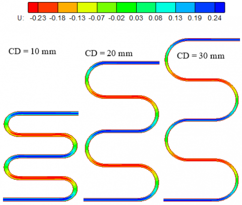
Figure 4 presents the streamwise velocity for fluid flow in serpentine mini-channel with various curvature diameters at Re=500. At the mini-channel inlet, both flow and heat transfer conditions are fully developed. The fluid flows predominantly in the axial direction of the serpentine mini-channel, with a nearly constant velocity profile maintained throughout the entire flow path length. This behavior is primarily due to the domination of viscous forces, which suppress secondary flows (there are no secondary flows). It is observed that within the curvature zone of the mini-channel, a region of reduced flow velocity emerges as the curvature diameters increases. Furthermore, it is noted that a smaller curvature diameter results in a more vigorous and intense flow, enhancing fluid mixing and consequently improving heat transfer. Therefore, it can be concluded that a reduction in curvature diameter leads to a growth in the friction coefficient. In the straight channel region, the flow characteristics remain consistent across various curvature diameters.
Figure 4. Streamwise velocity contours for different curvature diameters at Re=500
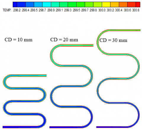
Figure 5 present the temperature contours for serpentine mini-channel with different curvature diameters at Re=500. The behavior of fluid mixing along the curvature of the serpentine mini-channel differs significantly from that of the straight mini-channel. This fluid mixing plays a critical role in affecting heat transfer. The extent of fluid mixing is closely associated with either an improvement or deterioration in heat transfer performance. It is observed that in the curved region, heat transfer is limited due to the reduced flow velocity and the heightened thickness of the boundary layer in this zone. Furthermore, it's noted that the curved area expands as the curvature diameter increases, thus, the most efficient heat transfer occurs at the smallest curvature diameter. Regarding the straight channel region, it's important to mention that the boundary layer thickness rises with the increasing curvature diameter, resulting in a decrease in heat transfer efficiency in this region. It is obvious that the heat transfer diminishes in the post-bending region as the curvature diameter increases.
Figure 5. Isotherms contours for different curvature diameter at Re=500
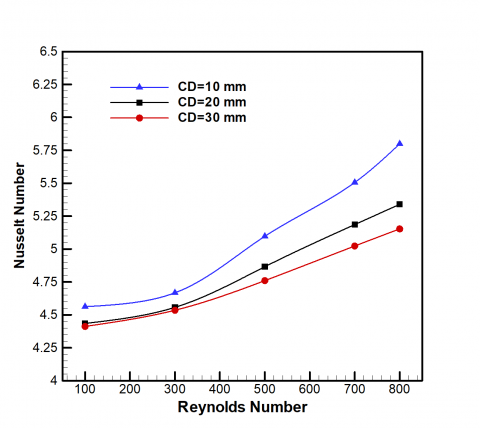
Figure 6. Effect of the curvature diameters on the average Nusselt number
Figure 6 displays the relationship between Re versus the average Nu for different curvature diameters. It is clear that as the Re increases, the average Nu also increases for all curvature diameters. This can be attributed to the heightened temperature gradient at the two surfaces with increasing Re and a reduction in the thickness of thermal boundary layers. As the curvature diameters in the serpentine MCHS increases, the Nu tends to decrease. This decrease is due to an increase in thermal boundary layer thickness at the walls in the curvature regions. These effects are primarily attributed to less effective fluid flow in the curvature region, ultimately influencing the Nu. Therefore, the overall Nu enhanced about 12.5% at Re=1000 and CD=10 mm compared with other cases.
Figure 7 displays the variation of friction factor with Re for different curvature diameters. As Re increases, the friction factor tends to decrease for all curvature diameters. In laminar flow regimes, fluid motion is more orderly, leading to lower frictional losses along the mini-channel walls. Furthermore, it is found that the curvature diameter does not significantly affect the coefficient of friction when Re300>. For Re>300, results indicate that the friction factor increases with decreasing in the curvature diameter. This is attributed to concentrate the flow patterns in the curvature region, which lead to increased resistance to fluid motion and higher frictional losses along the mini-channel walls (see Figure 4).
Figure 7. Effect of the curvature diameters on the friction factor
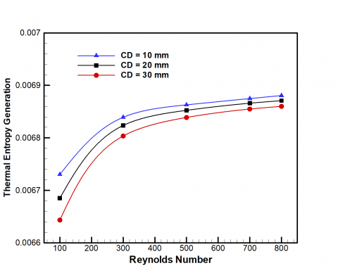
Figure 8. Effect of the curvature diameters on the thermal entropy generation
Figures 8 and 9 illustrate the variation of thermal and viscous entropy generation, respectively, versus Re for different curvature diameters. It is observed that both thermal and frictional entropy generation increase with the Re for a given curvature diameters. This is primarily attributed to the increases in the velocity and temperature gradients. Furthermore, curvature diameters in mini-channels have a direct influence on thermal and frictional entropy generation. As the curvature diameter increases, the entropy generation generally reduces. This decrease is primarily due to intensify the temperature and velocity gradients within the curvature regions. The combination of higher velocity and temperature gradients results in elevated entropy generation, which affects the overall performance of the heat sink.
The effect of curvature diameters on Bejan number are illustrated in Figure 10. It can be noted that as Re increases, Bejan number decreases. This result occurs because thermal entropy generation takes dominant at lower Re, whereas the influence of frictional entropy generation becomes more prominent at higher Re. As the curvature diameters increases, Bejan number typically shows an increase as well. Bejan number represents the ratio of heat transfer irreversibility to the total entropy generation, and larger curvature diameters often lead to more intricate flow patterns. This results in a higher Bejan number.
Figure 9. Effect of the curvature diameters on the viscous entropy generation
Figure 10. Effect of the curvature diameters on the Bejan number
Figure 11 shows the effect of curvature diameters on the performance evaluation criteria factor (PEC). The friction factor and average Nu were computed for the serpentine MCHS and compared to those of the straight mini-channel to evaluate the hydrothermal performance factor. The Results revealed that the curvature diameters have a clear effect on the performance factor. When Re>400 and Re>170 at CD=30 mm and CD=10 mm, respectively, the results indicated that the value of performance factor exceeded unity but decreased as Re increased. Furthermore, the performance factor is less than unity when CD=20 mm for all Re values. This is indicating that the increase in friction losses outweighed the heat transfer enhancement for this value of curvature diameter. The maximum PEC is approximately (1.05) which can be obtained when CD=30 mm and Re=100.
Figure 11. Effect of the curvature diameters on the performance evaluation criteria factor (PEC)
This paper presented a numerical study of the flow field, heat transfer enhancement, and entropy generation within a serpentine MCHS over Re range from 100 to 800. By using the finite volume technique based on the SIMPLE algorithm, the two-dimensional governing continuity, momentum, and energy equations have been solved. The study analyzed the effect of curvature diameters (CD=10, 20, and 30 mm) and Re on the overall Nu, thermal and viscous entropy generation, friction factor and the performance evaluation criteria (PEC). The findings lead to the following conclusions:
Therefore, the optimal design for a heat sink that provide the best thermal performance, lowest entropy production and a more compact size is numerically suggested to be a serpentine mini-channel with a particular curvature diameter.
|
CD |
curvature diameters |
|
f |
friction factor |
|
h |
heat transfer coefficients (W/m2.K) |
|
H |
channel height (mm) |
|
K |
thermal conductivity (W/m.K) |
|
L |
straight section length (mm) |
|
N |
dimensionless entropy generation |
|
Nu |
Nusselt number |
|
Pr |
Prandtl number |
|
P |
pressure (Pa) |
|
Re |
Reynolds number (Re=ρ uin H/µ) |
|
T |
temperature (K) |
|
u, v |
velocity components (m/s) |
|
U, V |
dimensionless velocity component |
|
x, y |
2D cartesian coordinates (mm) |
|
X, Y |
dimensionless cartesian coordinates |
|
Greek ymbols |
|
|
$\rho$ |
density (kg/m3) |
|
θ |
non-dimensional temperature |
|
Δp |
pressure drop (pa) |
|
µ |
dynamic viscosity (N.s/m2) |
|
Subscripts |
|
|
ave |
average value |
|
ff |
frictional entropy generation |
|
in |
inlet |
|
tot |
total |
|
th |
thermal entropy generation |
|
ser |
serpentine |
|
str |
straight |
[1] Msk, K., Hsa, G. (2013). Heat dissipation in a computer. Journal of Energy Technologies and Policy, 3(6): 43-49.
[2] Arshad, W., Ali, H.M. (2017). Experimental investigation of heat transfer and pressure drop in a straight minichannel heat sink using TiO2 nanofluid. International Journal of Heat and Mass Transfer, 110: 248-256. https://doi.org/10.1016/j.ijheatmasstransfer.2017.03.032
[3] Ghasemi, S.E., Ranjbar, A.A., Hosseini, M.J. (2017). Experimental and numerical investigation of circular minichannel heat sinks with various hydraulic diameter for electronic cooling application. Microelectronics Reliability, 73: 97-105. https://doi.org/10.1016/j.microrel.2017.04.028
[4] Al-Neama, A.F., Khatir, Z., Kapur, N., Summers, J., Thompson, H.M. (2018). An experimental and numerical investigation of chevron fin structures in serpentine minichannel heat sinks. International Journal of Heat and Mass Transfer, 120: 1213-1228. https://doi.org/10.1016/j.ijheatmasstransfer.2017.12.092
[5] Gorzin, M., Ranjbar, A.A., Hosseini, M.J. (2022). Experimental and numerical investigation on thermal and hydraulic performance of novel serpentine minichannel heat sink for liquid CPU cooling. Energy Reports, 8: 3375-3385. https://doi.org/10.1016/j.egyr.2022.02.179
[6] Abed, W.M., Whalley, R.D., Dennis, D.J.C., Poole, R.J. (2015). Numerical and experimental investigation of heat transfer and fluid flow characteristics in a micro-scale serpentine channel. International Journal of Heat and Mass Transfer, 88: 790-802. https://doi.org/10.1016/j.ijheatmasstransfer.2015.04.062
[7] Thangam, S., Hur, N. (1990). Laminar secondary flows in curved rectangular ducts. Journal of Fluid Mechanics, 217: 421-440. https://doi.org/10.1017/S0022112090000787
[8] Imran, A.A., Mahmoud, N.S., Jaffal, H.M. (2018). Numerical and experimental investigation of heat transfer in liquid cooling serpentine mini-channel heat sink with different new configuration models. Thermal Science and Engineering Progress, 6: 128-139. https://doi.org/10.1016/j.tsep.2018.03.011
[9] Chen, Y., Peng, B., Hao, X., Xie, G. (2014). Fast approach of Pareto-optimal solution recommendation to multi-objective optimal design of serpentine-channel heat sink. Applied Thermal Engineering, 70(1): 263-273. https://doi.org/10.1016/j.applthermaleng.2014.05.004
[10] Zhang, J., Zhang, T., Prakash, S., Jaluria, Y. (2014). Experimental and numerical study of transient electronic chip cooling by liquid flow in microchannel heat sinks. Numerical Heat Transfer, Part A: Applications, 65(7): 627-643. https://doi.org/10.1080/10407782.2013.846594
[11] Jaffal, H.M., Freegah, B., Hussain, A.A., Hasan, A. (2021). Effect of the fluid flow fragmentation on the hydrothermal performance enhancement of a serpentine mini-channel heat sink. Case Studies in Thermal Engineering, 24: 100866. https://doi.org/10.1016/j.csite.2021.100866
[12] Mondal, S., Majumder, S.K. (2020). Heat transport based on hydrodynamics and the local entropy generation rate in straight and serpentine rectangular packed narrow channels. Applied Thermal Engineering, 171: 115057. https://doi.org/10.1016/j.applthermaleng.2020.115057
[13] Akbarzadeh, M., Rashidi, S., Esfahani, J.A. (2017). Influences of corrugation profiles on entropy generation, heat transfer, pressure drop, and performance in a wavy channel. Applied Thermal Engineering, 116: 278-291. https://doi.org/10.1016/j.applthermaleng.2017.01.076
[14] Ratul, R.E., Ahmed, F., Alam, S., Karim, M.R., Bhuiyan, A.A. (2023). Numerical study of turbulent flow and heat transfer in a novel design of serpentine channel coupled with D-shaped jaggedness using hybrid nanofluid. Alexandria Engineering Journal, 68: 647-663. https://doi.org/10.1016/j.aej.2023.01.061
[15] Anqi, A.E. (2023). Numerical investigation of heat transfer and entropy generation in serpentine microchannel on the battery cooling plate using hydrophobic wall and nanofluid. Journal of Energy Storage, 66: 106548. https://doi.org/10.1016/j.est.2022.106548
[16] Wang, D., Ali, M.A., Sharma, K., Kh, T.I., Alali, A.F., Almohana, A.I., Almojil, S.F. (2023). The application of two-phase model to assess the nanofluid entropy generation in serpentine and double-serpentine heatsinks. Engineering Analysis with Boundary Elements, 147: 39-50. https://doi.org/10.1016/j.enganabound.2022.10.020
[17] Spalding, D.B. (1986). Computational fluid mechanics and heat transfer. Journal of Fluid Mechanics, 172(1): 564. https://doi.org/10.1017/S0022112086211878
[18] Kock, F., Herwig, H. (2005). Entropy production calculation for turbulent shear flows and their implementation in CFD codes. International Journal of Heat and Fluid Flow, 26(4): 672-680. https://doi.org/10.1016/j.ijheatfluidflow.2005.03.005
[19] Dahham, M.N., Ahmed, M.A. (2021). Numerical Investigation on heat transfer enhancement and entropy generation in a triangular ribbed-channel using nanofluid. Anbar Journal of Engineering Sciences, 12(1): 65-75. https://doi.org/10.37649/aengs.2021.171199
[20] Versteeg, H.K., Malalasekera, W. (2007). An Introduction to Computational Fluid Dynamics, Second Edition. Pearson Education Limited. www.pearsoned.co.uk/versteeg.
[21] Tannehill, J.C., Anderson, D.A., Pletcher, R.H. (1997). Computational Fluid Mechanics and Heat Transfer (2nd ed.). New York.
[22] Ferziger, J.H., Perić, M. (2002). Computational Methods for Fluid Dynamics. Springer.
[23] Ahmed, M.A., Yusoff, M.Z., Ng, K.C., Shuaib, N.H. (2015). Numerical and experimental investigations on the heat transfer enhancement in corrugated channels using SiO2-water nanofluid. Case Studies in Thermal Engineering, 6: 77-92. https://doi.org/10.1016/j.csite.2015.07.003
[24] Alabdaly, I.K., Ahmed, M.A. (2019). Numerical study on hydrothermal performance factor using jet impingement and nanofluid. Anbar Journal of Engineering Science, 10(2): 308-315. https://doi.org/10.37649/aengs.2022.171374
[25] Ahmed, M.A., Alabdaly, I.K., Hatema, S.M., Hussein, M.M. (2023). Numerical investigation of hydrothermal performance and entropy generation through backward facing step channel with oval rib. International Journal of Heat and Technology, 41(5): 1349-1357. https://doi.org/10.18280/ijht.410526
[26] Mohammed, M.K., Ahmed, M.A. (2018). Numerical study on the convective heat transfer of nanofluid flow in channel with trapezoidal baffles. Anbar Journal of Engineering Science, 7(3): 185-194. https://doi.org/10.37649/aengs.2018.145597
[27] Ahmed, M.A., Shuaib, N.H., Yusoff, M.Z., Al-Falahi, A.H. (2011). Numerical investigations of flow and heat transfer enhancement in a corrugated channel using nanofluid. International Communications in Heat and Mass Transfer, 38(10): 1368-1375. https://doi.org/10.1016/j.icheatmasstransfer.2011.08.013
[28] Mashan, A.K., Abed, W.M., Ahmed, M.A. (2021). Numerical investigation of hydraulic-thermal performance for a double-pipe heat exchanger equipped with 45°-helical ribs. Anbar Journal of Engineering Science, 9: 193-202. https://doi.org/10.37649/aengs.2021.171187
[29] Alabdaly, I.K., Ahmed, M.A. (2019). Numerical investigation on the heat transfer enhancement using a confined slot impinging jet with nanofluid. Propulsion and Power Research, 8(4): 351-361. https://doi.org/10.1016/j.jppr.2019.06.004
[30] Yarmand, H., Ahmadi, G., Gharehkhani, S., Kazi, S.N., Safaei, M.R., Alehashem, M.S., Mahat, A.B. (2014). Entropy generation during turbulent flow of zirconia-water and other nanofluids in a square cross section tube with a constant heat flux. Entropy, 16(11): 6116-6132. https://doi.org/10.3390/e16116116
[31] Ahmed, M.A., Yusoff, M.Z., Ng, K.C., Shuaib, N.H. (2014). Effect of corrugation profile on the thermal-hydraulic performance of corrugated channels using CuO-water nanofluid. Case Studies in Thermal Engineering, 4: 65-75. https://doi.org/10.1016/j.csite.2014.07.001