Syaiful*![]() | Muhammad Untung Zaenal Priyadi
| Muhammad Untung Zaenal Priyadi![]() | Bambang Yunianto | Nazaruddin Sinaga
| Bambang Yunianto | Nazaruddin Sinaga![]()
© 2024 The authors. This article is published by IIETA and is licensed under the CC BY 4.0 license (http://creativecommons.org/licenses/by/4.0/).
OPEN ACCESS
The inherent high thermal resistance of air impedes the heat transfer rate from tube surfaces to airflow within channels. This study aims to mitigate this issue by deploying perforated convex delta winglet pairs as vortex generators (VGs), strategically arranged in-line to reduce thermal resistance. Experimentation involved the installation of these vortex generators within the test section of a rectangular channel. Both convex delta winglet and perforated convex delta winglet pairs were mounted onto a flat plate in configurations of one, two, and three pairs. Airflow velocity within the channel was varied from 0.4 to 2.0 m/s at intervals of 0.2 m/s. Findings demonstrate an increase in the Nusselt number ratio by 1.5 and a 1.4 increment in the friction factor ratio with the utilization of three-row convex delta winglet pairs (CxDWPs) VGs at a Reynolds number of 8,724. Consequently, the thermal-hydraulic performance (TEF) approached a value of nearly 1.3 through the application of convex delta winglet vortex generators. This enhancement signifies the efficacy of convex delta winglets in augmenting heat transfer, thus addressing the challenge posed by air's thermal resistance.
convex delta winglet vortex generators (CxDW VGs), heat transfer enhancement, rectangular channel, thermal resistance reduction, airflow dynamics
Improving energy efficiency in fin and tube heat exchangers can be achieved by increasing the rate of heat transfer [1]. These exchangers have extensive applications in the chemical industry, power plants, and household AC systems. One of the main components of the air conditioner (AC) is the condenser, which is responsible for refrigerant condensation by applying air as a cooling fluid. However, air's high thermal resistance leads to a reduced rate of heat transfer. Therefore, vortex generator adoption is an effective method for reducing air thermal resistance [1]. These VGs generate eddies that increase the turbulence intensity and damage the boundary layer to promote a more even mixing of heat transfer between the hot and cold fluids [2]. Furthermore, the commonly used VG shapes are delta wing and winglet, as well as rectangular wing and winglet [3-5].
The study conducted by Lu and Zhai [6] showed an increasing angle of attack leads to an elevated value of Nu/Nu0 because of stronger longitudinal vortices (LV) generation. A previous study examined the influence of combining delta winglet pairs with a vortex generator (DWP VG) while varying arrangement, rotation angle, and distance between winglets on heat transfer [7]. The results showed an increase in Nu, with values ranging from 75% to 92% higher than those of plain channels. Baissi et al. [8] examined the relationship between delta VG baffles and heat transfer enhancement. The maximum TEF was achieved using perforated longitudinally curved delta-shaped baffles, reaching 2.21 at Re=11.382. In addition, Zhao et al. [9] placed DWP VGs in a U-shaped channel and observed that the CFD configuration produces a higher rate of heat transfer than CFU. This effect stemmed from the decrease in boundary layer thickness caused by the vortices generated. Khoshvaght et al. [10] examined the use of DWP VGs on plates inserted in channels. The results showed that bands with a non-uniform arrangement of the DWP VGs outperformed those in a uniform arrangement, providing better thermal performance. In a comprehensive study, Sadeghianjahromi and Wang [11] examined FTHE selection based on industrial requirements. Based on the findings, geometry significantly influences FTHE performance. Vortex generators NACA0024 show that the heat transfer improvement performance (HTEP) is 1.62 at Re=3923 with VG and chord line angles of 90 and 4, respectively. Gururatana et al. [12] examined a NACA0024 vortex generator on a tubular heat exchanger with a specified angle of attack of 60°, 90°, and 120°. This generator achieved a maximum HTEP of 1.62 at a low Reynolds number.
Luo et al. [13] have analyzed the effect of corrugation and VG angle on corrugated fins. The results showed a 26.4% increase in Thermal Enhancement Factor (TEF) for the new VG combination. Also, numerical analysis of the plain and wavy Finned-Tube Heat Exchanger (FTHE) angle on thermo-hydraulic performance was conducted by Ke et al. [14], with variations in the angle of attack of 15°, 30°, 45°, 60°, and 75°. The results showed the heat transfer performance/volume (Qv) and pumping power/volume (Pv) increased by 12.5% and 7.41%, respectively, when using DWP on corrugated FTHE. Furthermore, Siwi et al. [15] and Hendraswari et al. [16] conducted a numerical analysis of DWP, CDWP, RWP, and CRWP with an angle of 15°. The study showed the concave VG outperformed the flat VG shape due to the generation of more significant vortices. Gupta et al. [17] conducted simulations and experiments to improve heat exchanger (HE) performance using hollow VGs. The results showed hollow VG with a common flow-up (CFU) configuration increased heat transfer by 34% compared to simulations without VG.
Boukhadia et al. [18] examined hole shape influence, considering square, triangle, and circle configurations on VG. The results showed that VG with circular holes achieved a maximum TPF of 2.14. Meanwhile, Han et al. [19] focused on enhancing the rate of heat transfer and hole diameter and placement influence on the VG. The results showed the optimum hole diameter was d=5 mm, and hole placement in the vertical direction was c=4.5 mm, and horizontally, e=18 mm. Furthermore, Song and Tagawa [20] examined a staggered DWP VG arrangement to raise heat transfer in a flat-tube-fin HE. From the findings, the rise in longitudinal vortex intensity, friction factor, and Nusselt number were 30.4%, 18.5%, and 33.9%, respectively. Li et al.'s [21] analysis involved convex-fin VG in the airways. The convection heat transfer coefficient of convex-fin VG was higher by 25%. Ke et al. [22] simulated DWP VG with different configurations, including common flow-down (CFD), CFU, and mixed, as well as VG aspect ratio on a rectangular channel. The VG with a small aspect ratio and the CFU configuration outperformed the CFD configuration. Conversely, VG with a larger aspect ratio and CFD are more advantageous than CFU. In addition, Wijayanta et al. [23] analyzed variation in the pitch ratio of the Delta Wing (DW) to raise heat transfer in exchangers. From the findings, DW-VG led to a 177% rise in heat transfer compared to plain tubes. Tian et al. [24] analyzed the VG placement effect on various channel shapes, including circles, ellipses, and flats, each with conventional and new configurations to increase heat transfer. The results showed the superiority of the new configuration of circular channels over elliptical and flat shapes in thermal performance. Moosavi et al. [25] examined the effect of placing a TVG in the microchannel on heat transfer performance. The results showed a significant 226% enhancement in heat transfer greater than that of plain microchannels.
Based on the description above, it is evident that DWP VG offers higher heat transfer improvements. Information regarding heat transfer improvements using convex-shaped DWP VG is limited. The use of convex delta winglet vortex generators has never been studied for heat transfer improvements. Therefore, this study introduces a novel approach by using CxDWPs and PCxDWPs (perforated convex delta winglet pairs) to enhance heat transfer from the hot tube surfaces to the airflow within a channel. This research targets the use of a vortex generator to increase heat transfer from the surface of hot tubes to the fluid flow in a rectangular channel through experiments on a laboratory scale. Experiments were conducted to examine the transfer improvement by passing air through an arrangement of hot tubes with VG in a rectangular channel. The VGs were positioned in line to analyze the VG configuration effect on thermal performance. Additionally, flow visualization aimed to analyze the LV structures of CxDWPs and PCxDWPs.
2.1 Test specimen
The test specimens consist of six tube rows, each with 19 mm diameter and 55 mm height. These tubes are arranged in-line on aluminum fins measuring 1 mm in thickness of 1 mm, 500 mm in length, and 165 mm in 165 mm width where the VG was installed, such as in Figure 1. The CxDWPs and PCxDWPs are affixed on a plate with an angle of 15º. The VG varies between one, two, and three pairs, all arranged with an in-line. Figure 1(a) provides the top view geometry for three CxDWPs and PCxDWPs pairs arranged in-line. Figure 1(b) provides the side view geometry of the test specimen. Figure 1(c) shows the details of the perforated convex delta winglet vortex generator (PCxDWVG) geometry. Additionally, photos of the constructed test specimens are shown in Figure 2.
Figure 1. Geometry detail (a) top view of CxDWPs VGs’ three pairs, (b) side view of PCxDWPs VGs’ three pairs, (c) hole geometry view on VG
Figure 2. Photos of (a) CxDWPs VG one pair, (b) CxDWPs VGs two pairs, (c) CxDWPs VG three pairs
Figure 3. Test scheme of heat transfer rate and pressure drop
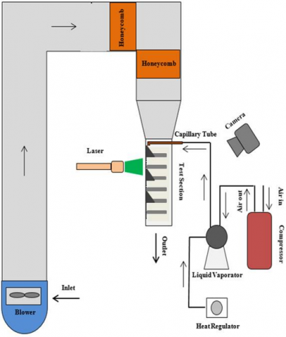
Figure 4. Flow visualization test scheme
2.2 Experiment procedure
Experiments were conducted in a rectangular channel measuring 370 cm in length, 8 cm in width, and 18 cm in height with a hydraulic diameter of 0.0922 m. The outlet temperature was measured using a type k thermocouple with temperatures from -200℃ to 1250℃ and ±0.5 accuracy. Additionally, temperature data were recorded using data acquisition equipment (Advantech USB-4718) with 0.1% accuracy and observed on the CPU. To regulate airflow within the channel, a Wipro-type YS7112 blower located at the end of the channel was used to draw in air. Data collection was carried out in the Mechanical Engineering Thermofluid Laboratory at Diponegoro University. When taking temperature data, six tubes were heated until they reached steady temperature without airflow. The airflow passed through the straightener which consists of pipes with 5 mm diameter and 290 mm length along with a wire mesh on the inlet side to ensure uniform airflow within the channel. Subsequently, the airflow passed through the test specimen with six tubes arranged in line. Each was heated at 40 W, with VGs installed on the fins on both sides of the tube. The airflow velocity within the channel is regulated by a Mitsubishi Electric type FR-D700 inverter and ± 0.01 accuracy and 0.4 to 2.0 m/s velocity with 0.2 m/s intervals. The velocity was calculated using hotwire anemometer (Lutron type AM-4204) with ± 0.1 accuracy. The pressure drop within the channel was monitored by a pressure micromanometer (Fluke 922) with ±0.05 accuracy. Furthermore, the micromanometer was linked to the pitot tubes at the inlet and outlet test section. The study setup is illustrated in Figure 3.
In this study, flow visualization aimed to analyze LV generated by VGs. The primary airflow is drawn by a blower (Aeromax Electric Motor type AE 63M2-2) and passes through a honeycomb to ensure uniform flow. Subsequently, the air passes through the test section at 1 m/s velocity. The smoke generated by the paraffin using a liquid-vaporator is compressed by a compressor (Daikin type YZG-23R AY1). This smoke is directed through a capillary tube at a velocity close to the main flow rate. Smoke passes through the test section, both with and without VGs. Furthermore, the flow is captured by a rectangular cross-sectional area using a laser beam directed at a glass tube. The flow structure in this rectangular cross-section is recorded by a digital camera (Canon EOS 60D). The camera monitors the LV structure created by the VGs during this as in Figure 4.
2.3 Parameter definition
The parameters used include:
$\overline{N u}=\frac{h D_h}{\lambda}$ (1)
where, Dh, h, and λ are the hydraulic diameter, convection heat transfer coefficient, and air thermal conductivity, respectively.
$h=\frac{q}{A_T \Delta T_{L M T D}}$ (2)
$D_h=\frac{4 A_c}{P}$ (3)
where, q, AT, ΔTLMTD, Ac, and P are convection rate on heat transfer, tube hot surface area, log-mean temperature difference, and channel cross-sectional area, respectively.
$q=\dot{m} C_p\left(\bar{T}_{\text {out }}-\bar{T}_{\text {in }}\right)$ (4)
$\Delta T_{L M T D}=\frac{\left(\bar{T}_{t u b e}-\bar{T}_{out }\right)-\left(\bar{T}_{tube }-\bar{T}_{in }\right)}{\ln \left[\left(\bar{T}_{tube }-\bar{T}_{out }\right)-\left(\bar{T}_{tube }-\bar{T}_{in }\right)\right]}$ (5)
$\dot{m}=\rho u_{i n} A_c$ (6)
where, $\dot{m}, C_p, \bar{T}_{\text {out }}, \bar{T}_{\text {in }}, \bar{T}_{\text {tube }}, \rho$ are mass flow rate, air specific heat, average outlet air temperature, inlet air temperature, tube surface temperature, and the density of air.
$\Delta P=\bar{P}_{\text {in }}-\bar{P}_{\text {out }}$ (7)
where, Pin, dan Pout are the average pressure on the inlet and outlet sides.
In this study, the thermal-hydraulic performance was obtained by evaluating TEF and friction factors. Meanwhile, the advantage of using VGs is determined by the CBR parameter. TEF and CBR are defined as follows:
$TEF=\frac{\frac{\overline{N u}}{\overline{N u_0}}}{\left(\frac{f}{f_0}\right)^{\frac{1}{3}}}$ (8)
where, subscript 0 is the baseline condition (without VGs).
$f=\frac{2 \Delta P D_h}{\rho V^2(L+6 D)}$ (9)
where, V & L are air density, inlet air velocity, and test specimen plate length.
$\mathrm{CBR}=\frac{\% \Delta P}{\% \Delta N u}$ (10)
2.4 Validation
Validation aimed to ensure the accuracy of the experiments, using Whitaker's experimental results for comparison [26]. Also, this was conducted by making a Nusselt number comparison with air flowing across a tube in a channel within the Reynolds number range of 2,000 to 10,000. The results can be referred to in the study of Effendi et al. [27].
3.1 VG influence on heat transfer
Heat transfer from the tube's surface to the airflow in the channel is significantly influenced by the flow structure. Turbulent flow, which enhances fluid mixing, leads to a rate of heat transfer to rise. The VGs installation on the fins can enhance the rate, and this heat transfer improvement is evaluated by comparing the Nusselt number between the test specimens affixed on the VGs and the baseline. In this study, VGs were varied with and without holes at various Reynolds numbers of VGs. Figure 5 shows the Nusselt to the Reynolds number ratios for these VG configurations. The Nusselt numbers for CxDWP with and without holes increase as the Reynolds number rises. In addition, Figure 5 shows the effectiveness of VGs in enhancing heat transfer within the channel. VGs generate LV which allows hot fluid to mix near the tube's surface with colder fluid in the main flow [28]. In addition, the number of VGs installed also affects the increase in heat transfer from the tube surface to the fluid in the channel. Overall, the rate across all cases increased along with the Reynolds number.
Figure 5. The Nusselt to the Reynolds number ratio for the number of the pair (one, two, and three)
From Figure 5, there is the effect of installing various VGs on heat transfer. The rate increases with both VGs and the Reynolds number. Furthermore, VGs with holes exhibit a lower Nusselt number ratio than those without. This is due to the holes in the VGs generating jet flow, which diminishes the longitudinal vortex. The jet flow generated by the VG holes reduces the stagnation, therefore facilitating local heat transfer. [19]. This study observed that the Nusselt number ratio of the mounting CxDWPs without holes was 6% higher than that of the CxDWPs with holes. From Figure 5, it is observed that the percentage reduction in the Nusselt number ratio of PCxDWP is 10.2% than that of CxDWP with three pairs of VGs in the laminar case and reduced by 5.3% for the turbulent case at Re=11,200. This indicates that the holes in the VG reduce the heat transfer rate by no greater than 10%.
3.2 VG effect on friction factor ratio
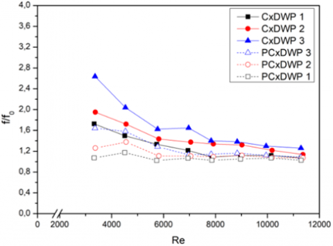
Figure 6. f/f0 ratio in three pairs CxDWP VGs with and without in-line configuration apertures in various Reynolds number
The installation of VGA led to a pressure drop, and this can be evaluated by the friction factor (f/f0) ratio. Figure 6 shows a comparison of the f/f0 ratios across different Reynolds numbers. It is evident in Figure 6, that the friction factor ratio decreases with raising Reynolds number. Then, it causes VG to increase the flow resistance within, consequently increasing the pressure drop [7]. Therefore, perforated VGs are used to reduce the friction factor. The holes within the VGs decrease the frontal area, obstructing the main flow. Additionally, the jet flow generated by the holes reduces stagnant flow, ultimately lowering pressure drop [15].
The friction factor for the three-row CxDWP without holes was 60% higher than those with holes. This difference occurs from the larger frontal area of the three-row CxDWP without holes compared to those with holes. In CxDWP VGs with holes, the highest reported f/f0 are 1.07, 1.26, and 1.64 at a Reynolds number of 4500, respectively. In the laminar case with three pairs of VGs, the friction factor ratio for the use of PCxDWP is reduced by 39% compared to that of CxDWP and is reduced by 16.7% for the turbulent case (Re=11,200). This indicates that the holes in the VG can significantly reduce the friction factor ratio which is greater for the laminar case.
3.3 VG effect on thermo-hydraulic performance
TEF is a measure of the HE thermo-hydraulic performance because of vortex generator installation [29]. This performance is determined by comparing the heat transfer raise to the improvement in pressure drop caused by VG installation. Figure 7 shows the TEF comparison for the installation of one, two, and three CxDWP VGs pairs with and without holes in an in-line configuration at various Reynolds numbers. In general, CxDWP without holes exhibit higher TEF values compared to VGs with holes at similar Reynolds numbers. At number 8,000, the three-line CxDWP with holes shows a TEF 1% higher. This is due to the heat transfer improvement being more significant than the pressure drop on CxDWP VGs with holes. The convex walls of the CxDWP generate vortices reducing the wake region and increasing heat transfer from the cylinder side to the mainstream [17, 28, 30]. The holes in the VGs are also able to eliminate stagnation areas to increase the thermo-hydraulic performance. At the lowest Reynolds number, the use of three PCxDWPs increases the TEF by 5.9% over that of CxDWP and reaches almost the same value at the highest Reynolds number. This indicates that the holes in the VG slightly improve the thermal-hydraulic performance at low-velocity fluid flow.
Figure 7. TEF in mounting CxDWP VGs with and without holes for in-line configurations in various Reynolds number
3.4 Cost-benefit ratio
The CBR serves as an economic evaluation value of heat transfer enhancement achieved. It is determined by comparison of the percentage rise in pressure drop with those in Nusselt number for VGs with and without holes. CBR calculates the heat transfer efficiency of the exchanger concerning the associated costs [24]. Figure 8 shows the CBR values across different uses of VGs at varying Reynolds numbers. In the case of CxDWP three pairs with holes, lower CBR factors were observed compared to those of one and two pairs of VGs without holes. This is because the three-pair VGs with holes have a higher improvement in thermal performance with a low improvement in pressure drop. Therefore, a lower CBR factor indicates better thermal performance and vice versa. At the lowest Reynolds number, the CBR using three PCxDWPs is reduced by 33.3% compared to that of CxDWP and 7.7% at the highest Reynolds number. This indicates that the holes in the VG can add economic value compared to the VG without holes.
Figure 8. CBR in mounting CxDWP VGs with and without holes with in-line configuration in various Reynolds number
3.5 Flow visualization
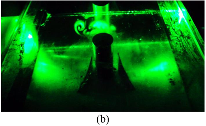
Figure 9. LV visualization generated from mounting (a) CxDWP without holes, (b) CxDWP with holes
Flow visualization tests aimed to identify the flow structure formed after passing through the VGs. These tests were conducted under low light conditions to ensure a clear observation of the longitudinal vortex structure. Furthermore, the two-dimensional vortex longitudinal structure was captured by directing a laser beam at a transparent solid cylinder. Figure 9 shows the longitudinal vortex structure generated by CxDWP VGs with and without holes. The heat transfer is affected by the longitudinal vortex radius. A larger radius of the longitudinal vortex causes heat transfer to rise. This is because the longitudinal vortex disrupts the flow boundary layer, facilitating the hot and cold fluid mix [27]. Therefore, the installation of CxDWP VGs can raise heat transfer.
4.1 Heat transfer deviation
The mean, mean standard deviation, and overall error are applied to calculate the experimental data deviation [31].
Table 1. Tube surface temperature data on the baseline test with 0.4 m/s flow rate
|
Data |
Tw1(℃) |
Tw2(℃) |
Tw3(℃) |
Tw4(℃) |
Tw5(℃) |
Tw6(℃) |
|
1. |
49,191 |
51,214 |
48,323 |
49,769 |
47,802 |
51,271 |
|
2. |
49,183 |
51,177 |
48,316 |
49,791 |
47,766 |
51,264 |
|
3. |
49,145 |
51,168 |
48,307 |
49,753 |
47,786 |
51,255 |
|
4. |
49,121 |
51,173 |
48,282 |
49,728 |
47,761 |
51,259 |
|
5. |
49,153 |
51,205 |
48,285 |
49,731 |
47,735 |
51,262 |
|
6. |
49,100 |
51,151 |
48,290 |
49,736 |
47,769 |
51,267 |
|
7. |
49,098 |
51,150 |
48,230 |
49,734 |
47,738 |
51,294 |
|
8. |
49,089 |
51,141 |
48,250 |
49,667 |
47,729 |
51,228 |
The data in Table 1 help obtaining the average tube surface temperature ($\bar{T}_w$) using Eq. (11).
$\bar{T}_w=\frac{\bar{T}_{w 1}+\bar{T}_{w 2}+\bar{T}_{w 3}+\bar{T}_{w 4}+\bar{T}_{w 5}+\bar{T}_{w 6}}{6}$ (11)
From Eq. (11) the $\bar{T}_w$ value is 49.559℃. Furthermore, the average SD was obtained through Eq. (12).
$s_{T_w}=\sqrt{\frac{\sum_{i=1}^N\left(T_{w_i}-\bar{T}_w\right)^2}{N(N-1)}}$ (12)
The $S_{T_w}$ value is 0.194℃, to ensure the average value and deviation of $\bar{T}_w$ is 49.559±0.194℃. This $\bar{T}_w$ is still relevant regarding the accuracy of the thermocouple used (namely: ±0.5). Additionally, $\bar{T}_{i n}$ and $\bar{T}_{o u t}$ were 28.887 and 32.954℃. Furthermore, the average SD was obtained through Eqs. (13) and (14).
$S_{T_{i n}}=\sqrt{\frac{\sum_{i=1}^N\left(T_{i n_i}-\bar{T}_{\text {out }}\right)^2}{N(N-1)}}$ (13)
$S_{T_{\text {out }}}=\sqrt{\frac{\sum_{i=1}^N\left(T_{\text {out }_i}-\bar{T}_{\text {out }}\right)^2}{N(N-1)}}$ (14)
Therefore, $S_{T_{i n}}$ and $S_{T_{o u t}}$ were 0.012℃ and 0.045℃. Furthermore, the mean and deviation values of $\bar{T}_{i n}$ and $\bar{T}_{\text {out }}$ are 28.887±0.012℃ and 32.954±0.045℃. From this data, the data uncertainty value of the inlet and outlet temperatures is still below the accuracy value of the thermocouple used. Furthermore, the Q value at 0.4 m/s was 19.477 W. The error value Q was obtained through Eq. (15).
$E_{a_{r s s} Q}=\sqrt{\left(\Delta T_{\text {in }} \frac{\partial Q}{\partial T_{\text {in }}}\right)^2+\left(\Delta T_{\text {out }} \frac{\partial Q}{\partial T_{\text {out }}}\right)^2}$ (15)
where, $\frac{\partial Q}{\partial T_{i n}}=\frac{\dot{m} \cdot C_p\cdot(\sqrt{\frac{\sum_{i=1}^N\left(T_{i n_i}-\bar{T}_{\text {out }}\right)^2}{N(N-1)}}-\left.\sqrt{\frac{\sum_{i=1}^N\left(T_{\text {out }_i}-\bar{T}_{\text {out }}\right)^2}{N(N-1)}}\right)}{\sqrt{\frac{\sum_{i=1}^N\left(T_{i n_i}-\bar{T}_{\text {out }}\right)^2}{N(N-1)}}}$ and therefore, $\frac{\partial Q}{\partial T_{out}}=\frac{\dot{m} \cdot C_p\cdot(\sqrt{\frac{\sum_{i=1}^N\left(T_{i n_i}-\bar{T}_{out }\right)^2}{N(N-1)}}-\left.\sqrt{\frac{\sum_{i=1}^N\left(T_{out_i}-\bar{T}_{out }\right)^2}{N(N-1)}}\right)}{\sqrt{\frac{\sum_{i=1}^N\left(T_{out_i}-\bar{T}_{out }\right)^2}{N(N-1)}}}$. with $\Delta T_{\text {in }}=0.012^{\circ} \mathrm{C}$ and $\Delta T_{\text {out }}=0.045^{\circ} \mathrm{C}$ obtained the value, $E_{a_{r s s_Q}}$=0.028 W. Therefore, Q=19.477±0.028 W. Furthermore, LMTD was obtained through Eq. (5) and its value is 18.564℃. The error value of the LMTD was 0.077℃, obtained through Eq. (16).
$E_{a_{r s s_{ L M T D}}}=\sqrt{\begin{array}{c}\left(\Delta T_{i n} \frac{\partial L M T D}{\partial T_{\text {in }}}\right)^2+\left(\Delta T_w \frac{\partial L M T D}{\partial T_w}\right)^2 \\ +\left(\Delta T_{\text {out }} \frac{\partial L M T D}{\partial T_{\text {out }}}\right)^2\end{array}}$ (16)
Therefore, the LMTD value is 18.564 ±0.077℃. Nu was obtained through Eq. (1) at 0.4 m/s with 155.308 value. Furthermore, the calculation error for Nu becomes:
$E_{a_{r s s_{Nu}}}=\sqrt{\left(\Delta L M T D \frac{\partial N u}{\partial L M T D}\right)^2+\left(\Delta Q \frac{\partial N u}{\partial Q}\right)^2}$ (17)
Therefore, the Nu error value was determined to be 0.684. The Nu in the baseline case with 0.4 m/s inlet air velocity is 155.308±0.684. The convection heat transfer coefficient was obtained through Eq. (1) as 44.857 W/m2K.
$E_{a_{r s s_h}}=\sqrt{\left(\Delta N u \frac{\partial h}{\partial N u}\right)^2}$ (18)
Therefore, the error value of the convection heat transfer coefficient is 0.197 W/m2K. The convection heat transfer coefficient is h=44.857±0.197 W/m2K. Furthermore, the error value was obtained through Eq. (19) and the value obtained is 0.44%.
$\% Error _h=\left(\frac{E_{a_{r s s_h}}}{h}\right) 100 \%$ (19)
The same method is applied for all data. Table 2 shows the overall error value from the convection heat transfer coefficients when using CxDWPs and PCxDWPs VGs.
Table 2. Tube surface temperature data on the baseline test with 0.4 m/s flow rate
|
Data |
Overall Error |
|
|
CxDWPs (%) |
PCxDWPs (%) |
|
|
1. |
2.79 |
1.81 |
|
2. |
3.04 |
1.46 |
|
3. |
3.51 |
1.74 |
4.2 Pressure drop deviation
Table 3 shows the pressure drop test for the baseline case with 2 m/s velocity where the average value is determined using Eq. (20) and was obtained as 0.013 in H2O.
Table 3. Pressure drop data for the baseline case at 2 m/s velocity
|
Overall Error |
|||
|
Data |
ΔP |
Data |
ΔP |
|
1 |
0.013 |
16 |
0.012 |
|
2 |
0.013 |
17 |
0.013 |
|
3 |
0.013 |
18 |
0.012 |
|
4 |
0.013 |
19 |
0.012 |
|
5 |
0.012 |
20 |
0.013 |
|
6 |
0.013 |
21 |
0.013 |
|
7 |
0.013 |
22 |
0.012 |
|
8 |
0.012 |
23 |
0.013 |
|
9 |
0.013 |
24 |
0.012 |
|
10 |
0.013 |
25 |
0.013 |
|
11 |
0.013 |
26 |
0.013 |
|
12 |
0.013 |
27 |
0.013 |
|
13 |
0.012 |
28 |
0.013 |
|
14 |
0.012 |
29 |
0.012 |
|
15 |
0.013 |
30 |
0.012 |
$\Delta \bar{P}=\frac{\Delta P_1+\Delta P_2+\Delta P_3+\cdots+\Delta P_{30}}{30}$ (20)
The average standard deviation value is determined through Eq. (21) and was obtained to be 2.1×10⁻⁵ in H2O.
$s_{\Delta P}=\sqrt{\frac{\sum_{i=1}^N\left(\Delta P_i-\Delta \bar{P}\right)^2}{N(N-1)}}$ (21)
Thus, the pressure drop at 2 m/s velocity is 0.013±4.9×10⁻⁵ in H2O. Furthermore, the pressure drop error was obtained through Eq. (22) and the value is 0.47%. This deviation value is still below the accuracy value of the micromanometer used in this study.
$\% Error _{\Delta P}=\left(\frac{s_{\Delta P}}{\Delta \bar{P}}\right) 100 \%$ (22)
The similar method is applied for all data. Hence, the results of the error for pressure drop when using CxDWP and PCxDWP VGs can be seen in Table 4.
Table 4. Error pressure drop on CxDWP VGs with and without holes
|
Number of Pair |
Overall Error |
|
|
CxDWPs (%) |
PCxDWPs (%) |
|
|
1. |
0.49 |
2.20 |
|
2. |
0.51 |
0.55 |
|
3. |
0.74 |
1.70 |
This analysis examined the CxDWP VGs effect with and without holes. The thermal-hydraulic performance with CxDWP VGs was obtained by analyzing the Nusselt number and friction factor ratio, as well as TEF and CBR. It can be concluded:
This work was supported by the Faculty of Engineering (Fundamental Research, DIPA 2023), Diponegoro University. The authors are grateful to all research members, especially Lab. of Thermofluid of Mechanical Engineering of Diponegoro University Indonesia, Lab. of Aerospace Engineering Department of Bandung State Polytechnic, Indonesia.
|
Ac |
The cross-sectional area of the rectangular channel (m2) |
|
AT |
The total hot surface area of the tube (m2) |
|
CBR |
Cost benefit ratio (-) |
|
Cp |
Specific heat (J/(kg.K)) |
|
Dh |
Hydraulic diameter (m) |
|
f |
Friction factor (-) |
|
H |
Test section height (m) |
|
h |
Convection heat transfer coefficient (W/(m2.K)) |
|
L |
Test section length (m) |
|
Nu |
Nusselt number (-) |
|
P |
Pressure (Pa) |
|
ΔP |
Pressure drop along the flow (Pa) |
|
q |
Heat transfer rate (W) |
|
Re |
Reynolds number (-) |
|
T |
Temperature (K) |
|
TEF |
Thermal enhancement factor (-) |
|
u, v, w |
Components of velocity in the x, y, z directions (m/s) |
|
U |
Secondary flow rate (m/s) |
|
Uin |
Average velocity at inlet (m/s) |
|
x, y, z |
Direction in Cartesian coordinates (m) |
|
α |
Angle of attack (°) |
|
μ |
Dynamic viscosity (kg/(m.s)) |
|
ρ |
Density (kg/m3) |
|
0 |
Baseline case |
|
n |
Normal |
|
in |
Inlet |
|
out |
Outlet |
|
tube |
Hot tube |
|
m |
Average value |
|
LMTD |
Log-mean temperature difference |
[1] Oh, Y., Kim, K. (2021). Effects of position and geometry of curved vortex generators on fin-tube heat-exchanger performance characteristics. Applied Thermal Engineering, 189: 116736. https://doi.org/10.1016/j.applthermaleng.2021.116736
[2] Dogan, M., Igci, A.A. (2021). An experimental comparison of delta winglet and novel type vortex generators for heat transfer enhancement in a rectangular channel and flow visualization with stereoscopic PIV. International Journal of Heat and Mass Transfer, 164: 120592. https://doi.org/10.1016/j.ijheatmasstransfer.2020.120592
[3] Sadeghianjahromi, A., Kheradmand, S., Nemati, H., Wang, C.C. (2020). Heat transfer enhancement of wavy fin-and-tube heat exchangers via innovative compound designs. International Journal of Thermal Sciences, 149: 106211. https://doi.org/10.1016/j.ijthermalsci.2019.106211
[4] Yang, L., Xu, M., Wang, J., Song, L., Wang, J. (2021). Experimental and numerical analysis of a demister with vortex generators. Chinese Journal of Chemical Engineering, 33: 83-95. https://doi.org/10.1016/j.cjche.2020.07.045
[5] Raihan, M.F., Al-Asadi, M.T., Thompson, H.M. (2021). Management of conjugate heat transfer using various arrangements of cylindrical vortex generators in micro-channels. Applied Thermal Engineering, 182: 116097. https://doi.org/10.1016/j.applthermaleng.2020.116097
[6] Lu, G., Zhai, X. (2019). Effects of curved vortex generators on the air-side performance of fin-and-tube heat exchangers. International Journal of Thermal Sciences, 136: 509-518. https://doi.org/10.1016/j.ijthermalsci.2018.11.009
[7] Liu, H.L., Fan, C.C., He, Y.L., Nobes, D.S. (2019). Heat transfer and flow characteristics in a rectangular channel with combined delta winglet inserts. International Journal of Heat and Mass Transfer, 134: 149-165. https://doi.org/10.1016/j.ijheatmasstransfer.2019.01.004
[8] Baissi, M.T., Brima, A., Aoues, K., Khanniche, R., Moummi, N. (2020). Thermal behavior in a solar air heater channel roughened with delta-shaped vortex generators. Applied Thermal Engineering, 165: 113563. https://doi.org/10.1016/j.applthermaleng.2019.03.134
[9] Zhao, Z., Luo, L., Qiu, D., Wang, S., Wang, Z., Sundén, B. (2021). On the topology of vortex structures and heat transfer of a gas turbine blade internal tip with different arrangement of delta-winglet vortex generators. International Journal of Thermal Sciences, 160: 106676. https://doi.org/10.1016/j.ijthermalsci.2020.106676
[10] Khoshvaght-Aliabadi, M., Naeimabadi, N., Barzoki, F.N., Salimi, A. (2021). Experimental and numerical studies of airflow and heat transfer due to insertion of novel delta-winglet tapes in a heated channel. International Journal of Heat and Mass Transfer, 169: 120912. https://doi.org/10.1016/j.ijheatmasstransfer.2021.120912
[11] Sadeghianjahromi, A., Wang, C.C. (2021). Heat transfer enhancement in fin-and-tube heat exchangers–A review on different mechanisms. Renewable and Sustainable Energy Reviews, 137: 110470. https://doi.org/10.1016/j.rser.2020.110470
[12] Gururatana, S., Prapainop, R., Chuepeng, S., Skullong, S. (2021). Development of heat transfer performance in tubular heat exchanger with improved NACA0024 vortex generator. Case Studies in Thermal Engineering, 26: 101166. https://doi.org/10.1016/j.csite.2021.101166
[13] Luo, C., Wu, S., Song, K., Hua, L., Wang, L. (2019). Thermo-hydraulic performance optimization of wavy fin heat exchanger by combining delta winglet vortex generators. Applied Thermal Engineering, 163: 114343. https://doi.org/10.1016/j.applthermaleng.2019.114343
[14] Ke, H., Khan, T.A., Li, W., Lin, Y., Ke, Z., Zhu, H., Zhang, Z. (2019). Thermal-hydraulic performance and optimization of attack angle of delta winglets in plain and wavy finned-tube heat exchangers. Applied Thermal Engineering, 150: 1054-1065. https://doi.org/10.1016/j.applthermaleng.2019.01.083
[15] Siwi, A.R., Utomo, T.S., Wulandari, R. (2019). Numerical analysis of heat and fluid flow characteristics of airflow inside rectangular channel with presence of perforated concave delta winglet vortex generators. International Journal of Heat & Technology, 37(4): 1059-1070. https://doi.org/10.18280/ijht.370415
[16] Hendraswari, M.P., Su, M., Soetanto, M.F. (2021). Heat transfer enhancement inside rectangular channel by means of vortex generated by perforated concave rectangular winglets. Fluidika, 6(1): 43. https://doi.org/10.3390/fluids6010043
[17] Gupta, A., Roy, A., Gupta, S., Gupta, M. (2020). Numerical investigation towards implementation of punched winglet as vortex generator for performance improvement of a fin-and-tube heat exchanger. International Journal of Heat and Mass Transfer, 149: 119171. https://doi.org/10.1016/j.ijheatmasstransfer.2019.119171
[18] Boukhadia, K., Ameur, H., Sahel, D., Bozit, M. (2018). Effect of the perforation design on the fluid flow and heat transfer characteristics of a plate-fin heat exchanger. International Journal of Thermal Sciences, 126: 172-180. https://doi.org/10.1016/j.ijthermalsci.2017.12.025
[19] Han, Z., Xu, Z., Wang, J. (2018). Numerical simulation on heat transfer characteristics of rectangular vortex generators with a hole. International Journal of Heat and Mass Transfer, 126: 993-1001. https://doi.org/10.1016/j.ijheatmasstransfer.2018.06.081
[20] Song, K., Tagawa, T. (2018). The optimal arrangement of vortex generators for best heat transfer enhancement in flat-tube-fin heat exchanger. International Journal of Thermal Sciences, 132: 355-367. https://doi.org/10.1016/j.ijthermalsci.2018.06.011
[21] Li, X.Y., Li, Z.H., Tao, W.Q. (2018). Experimental study on heat transfer and pressure drop characteristics of fin-and-tube surface with four convex-strips around each tube. International Journal of Heat and Mass Transfer, 116: 1085-1095. https://doi.org/10.1016/j.ijheatmasstransfer.2017.09.076
[22] Ke, Z., Chen, C.L., Li, K., Wang, S., Chen, C.H. (2019). Vortex dynamics and heat transfer of longitudinal vortex generators in a rectangular channel. International Journal of Heat and Mass Transfer, 132: 871-885. https://doi.org/10.1016/j.ijheatmasstransfer.2018.12.064
[23] Wijayanta, A.T., Yaningsih, I., Juwana, W.E., Aziz, M., Miyazaki, T. (2020). Effect of wing-pitch ratio of double-sided delta-wing tape insert on the improvement of convective heat transfer. International Journal of Thermal Sciences, 151: 106261. https://doi.org/10.1016/j.ijthermalsci.2020.106261
[24] Tian, M.W., Khorasani, S., Moria, H., Pourhedayat, S., Dizaji, H.S. (2020). Profit and efficiency boost of triangular vortex-generators by novel techniques. International Journal of Heat and Mass Transfer, 156: 119842. https://doi.org/10.1016/j.ijheatmasstransfer.2020.119842
[25] Moosavi, R., Banihashemi, M., Lin, C.X., Chuang, P.Y.A. (2021). Combined effects of a microchannel with porous media and transverse vortex generators (TVG) on convective heat transfer performance. International Journal of Thermal Sciences, 166: 106961. https://doi.org/10.1016/j.ijthermalsci.2021.106961
[26] Whitaker, S. (1972). Forced convection heat transfer correlations for flow in pipes, past flat plates, single cylinders, single spheres, and for flow in packed beds and tube bundles. AIChE Journal, 18(2): 361-371. https://doi.org/10.1002/aic.690180219
[27] Effendi, Y., Prayogo, A., Syaiful, Djaeni, M., Yohana, E. (2022). Effect of perforated concave delta winglet vortex generators on heat transfer and flow resistance through the heated tubes in the channel. Experimental Heat Transfer, 35(5): 553-576. https://doi.org/10.1080/08916152.2021.1919245
[28] Awais, M., Bhuiyan, A.A. (2019). Enhancement of thermal and hydraulic performance of compact finned-tube heat exchanger using vortex generators (VGs): A parametric study. International Journal of Thermal Sciences, 140: 154-166. https://doi.org/10.1016/j.ijthermalsci.2019.02.041
[29] Sun, Z., Zhang, K., Li, W., Chen, Q., Zheng, N. (2020). Investigations of the turbulent thermal-hydraulic performance in circular heat exchanger tubes with multiple rectangular winglet vortex generators. Applied Thermal Engineering, 168: 114838. https://doi.org/10.1016/j.applthermaleng.2019.114838
[30] Mangrulkar, C.K., Dhoble, A.S., Chamoli, S., Gupta, A., Gawande, V.B. (2019). Recent advancement in heat transfer and fluid flow characteristics in cross flow heat exchangers. Renewable and Sustainable Energy Reviews, 113: 109220. https://doi.org/10.1016/j.rser.2019.06.027
[31] Doebelin, E.O. (1990). Measurement Systems Application Design, 4th ed. Singapore: McGraw-Hill.