Qicai Niu![]() | Xiaoshuai Guo*
| Xiaoshuai Guo*![]()
© 2023 IIETA. This article is published by IIETA and is licensed under the CC BY 4.0 license (http://creativecommons.org/licenses/by/4.0/).
OPEN ACCESS
In light of intensifying global climatic shifts, the durability analysis of bridge structures under fluctuating and intricate environmental conditions has gained paramount importance. Historically, durability assessment methodologies for bridges have been predominantly centered on static and dynamic stress analyses, with the multifaceted influences of climate change largely overlooked. Furthermore, a linear hypothesis underpins many of these methodologies, rendering them less adept at encapsulating complex thermal-mechanical interactions and inherent non-linear behaviours. In response to these limitations, a novel thermodynamic model, which duly incorporates climate change determinants, was introduced in this study. Emphasis was placed on two pivotal domains: the computation of shear bearing capacities in oblique bridge sections influenced by thermal-mechanical coupling, and the intricate nonlinear thermal-mechanical coupling analyses of bridges. By addressing these gaps, the study endeavours to present a more holistic and precision-driven methodology for evaluating bridge structure durability. Beyond its theoretical significance, this research is posited to further the pursuit of resilient and sustainable bridge design paradigms.
bridge structures, durability analysis, climate change, thermodynamic mtableodel, thermal-mechanical coupling, nonlinear calculation
Bridges, vital conduits connecting urban and rural locales, disparate regions, and even nations, have long been the subject of rigorous scrutiny in civil engineering, particularly concerning their structural safety and durability [1, 2]. Yet, as the impact of pronounced climate shifts – manifested through extreme temperature oscillations, elevated temperatures, and freezing-thawing cycles – becomes ever more palpable, bridge infrastructures find themselves confronted by an intricate matrix of environmental stressors [3-6]. It has been noted that such climatic variabilities induce alterations in the mechanical attributes of materials, subsequently modulating the stress-response and deformation characteristics of bridges [7, 8]. Given the protracted nature of global climatic metamorphosis, bridges are expected to retain their operational integrity and safety across extended temporal horizons. The pressing quandary arises: How might one infuse considerations of these climatic shifts into the durability analyses of bridge structures? Historically, bridge designs have predominantly leveraged retrospective meteorological datasets and statistical paradigms, methodologies that often falter in the face of the multifarious ramifications of climate change on bridge resilience [9-14]. Hence, the integration of a thermodynamic model, one that contemplates the complexities of climate change, is deemed indispensable. Such a model not only promises enhanced fidelity in replicating bridge behaviours across diverse climatic extremities but also furnishes engineers and policymakers with a more enlightened framework for bridge design and conservation – an approach that augments bridge longevity whilst attenuating prospective safety hazards [15-19]. It is observed that prevailing durability assessments of bridges are typically predicated upon rudimentary static and dynamic stress schematics, many of which eschew environmental modulations like temperature, humidity, and wind dynamics [20-22]. Furthermore, a preponderance of these models, anchored in linear hypotheses, are found wanting when tasked with delineating non-linear dynamics engendered by intricate thermal-mechanical interactions. Linear frameworks, for instance, are ill-equipped to encapsulate phenomena such as fatigue, fissuring, or other infrastructural impairments potentially induced by extreme thermal oscillations. Such lacunae not only erode the predictive veracity of these models but may inadvertently underplay the latent hazards confronting bridge structures.
This research elucidates two pivotal realms. Initially, attention is directed towards methodologies underpinning the calculation of shear bearing capacities in oblique bridge segments, especially under the purview of thermal-mechanical interactions. Herein, simulations embracing novel materials and intricate stress landscapes are explored, proffering a more encompassing and precision-oriented computational architecture. Subsequently, the discourse pivots to the behavioural intricacies of bridge frameworks within the ambit of non-linear thermal-mechanical synergies. Employing state-of-the-art numerical simulations buttressed by empirical validations, this investigation delineates methodologies to more judiciously anticipate bridge behaviours in the shadow of climatic perturbations. Beyond its academic contributions, this research also underscores pragmatic engineering trajectories, bolstering the ongoing evolution of bridge engineering design and stewardship.
Variations in external environmental factors, notably temperature fluctuations, are known to exert influence on bridge structures. In conditions where temperature experiences drastic shifts or attains extreme values, it has been observed that both the properties of bridge materials and the holistic stability of the structures are susceptible to change. In such scenarios, the traditional linear analysis methodologies are frequently found inadequate in predicting the bearing capacity and deformation behaviour of bridges with precision.
Particularly under the nuances of thermal-mechanical coupling, the shear bearing capacity of oblique bridge sections can manifest significant alterations. Elevated temperatures, for instance, might intensify the creep performance of certain materials, leading to a diminishment in their bearing capacity. Conversely, frigid conditions can augment the brittleness of these materials, escalating the probability of structural failures. Accurate computation of the shear bearing capacity for these oblique sections, therefore, not only emerges as pivotal for deciphering bridge performance in extreme thermal regimes but also stands as a foundational parameter in ensuring their prolonged durability and safety.
Accurate delineation of shear bearing capacity under thermal-mechanical stimuli enables engineers to evaluate bridge performance in varied climatic backdrops with heightened precision. Such evaluations are instrumental in orchestrating the design of robust bridge infrastructures, especially when juxtaposed against the backdrop of climate change and the augmented propensity for extreme weather phenomena. Beyond design implications, these meticulous computational methods also inform bridge maintenance and strategic management. For instance, once potential thermal-mechanical impacts are forecasted, preventative measures can be orchestrated in advance, encompassing strategies like structural fortifications, material replacements sensitive to thermal variances, and so forth. Such proactive interventions not only protract the operational lifespan of bridges but also curtail maintenance expenditures.
In examining the structural nuances of bridges post the manifestation of diagonal cracks, bridges were conceptualised as variable angle truss models in this study. Such modelling paradigms are especially adept at elucidating behaviours post the onset of diagonal fissures in the shear-bending sections. To achieve optimal predictive accuracy for the ultimate shear bearing capacity provisioned by bridge stirrups, an elemental body harbouring a complete diagonal crack must be incorporated in this segment. This model selectively omits the interlocking dynamics of aggregates and the dowel functions of longitudinal bars, thereby honing its analytical lens on the bearing capacity contributions of the stirrups. Figure 1 elucidates four illustrative sections situated at a bridge's terminus.
In the assessment of the shear bearing capacity of bridge oblique sections under the influence of thermal-mechanical coupling, several methodological steps were adopted. Initially, pertinent climate variables were designated as input parameters, these being grounded in tangible engineering or empirical datasets. Subsequently, a numerical model encapsulating the nuances of thermal-mechanical coupling was crafted, with its foundations rooted in the aforementioned input parameters and variable angle truss models. Consideration was then given to the ramifications of temperature oscillations on the mechanical properties of stirrups and concrete materials. Such deliberations are intrinsic to the comprehension of the influence of thermal-mechanical coupling on ultimate shear bearing capacity. In the final stage, post-contemplation of thermal influences, force balance conditions of the elemental body were employed to extrapolate the ultimate shear bearing capacity provisioned by the stirrups. Given the potential nonlinear associations between the effects of thermal-mechanical coupling and the bearing capacity of stirrups, especially within the confines of extreme thermal environments, the deployment of a nonlinear solution was deemed imperative for the accurate computation of ultimate shear bearing capacity.
Prior to embarking on calculations related to the shear bearing capacity of bridge oblique sections influenced by thermal-mechanical coupling, an in-depth analysis was undertaken on the shear bearing capacity intrinsic to stirrups. This also entailed determining the angular orientation of concrete diagonal fissures. Stirrups, essential structural elements in bridge architectures, are harnessed to confer lateral constraint and bolster shear bearing capacities. In scenarios punctuated by thermal-mechanical coupling dynamics, the operational performance of stirrups can be notably compromised. Erroneous assessments of the shear bearing capacity intrinsic to stirrups can inadvertently skew perceptions regarding the overarching durability and structural integrity of bridge entities, more so in climatic extremes. Precise analyses of the shear bearing capacities of stirrups thus pave the way for engineers to render more astute evaluations concerning structural resilience and maintenance stratagems. Figure 2 offers a schematic representation of the model tailored for the calculation of the shear bearing capacity of oblique bridge sections.
Figure 1. Illustrative depictions of quartet sections positioned at a bridge's terminus
Figure 2. Conceptual representation delineating the model for the evaluation of shear bearing capacity within oblique bridge segments
Let gCO be the spacing between the upper and lower longitudinal bars in the bridge, β be the angle of the diagonal crack, gCOCOTβ be the length of element body S, CY and LY be the shear force and bending moment on the surface beam section on the left side of S, respectively, CY be the shear force of the section on the right side of S, and LYgCOCOTβ be the increase of bending moment in LY. The geometric dimensions, material properties, and loading conditions of the element body were clarified first. On the left section of the element body, the balance condition was applied to decompose the total shear force acting on that section, which is usually the vertical and horizontal components. That is, CY was decomposed into oblique pressure FY and horizontal force BY, then there were:
$B^Y\,\,=\,\,C^Y\,\, \cot \beta$ (1)
$F^Y\,\,=\,\,\frac{C^Y}{\sin \beta}$ (2)
The stress under the action of FY in the bridge compression strut was calculated using the following equation:
$\delta_f^Y\,\,=\,\,\frac{F^Y}{n g_{C O} \cos \beta}\,\,=\,\,\frac{V^Y}{n g_{C O} \cos \beta \sin \beta}$ (3)
Horizontal force BY was distributed equally to the upper and lower longitudinal bars of the bridge, where (CY/2) COTβ distributed the bending moment equally to the upper and lower longitudinal bars as well as part of LY/gCO. The internal forces borne by the upper and lower longitudinal bars on the left side were determined using the balance condition. According to the positions and angles of the longitudinal bars, the internal forces borne by them were decomposed into axial force and bending moment. The equations for the internal forces borne by the upper and lower longitudinal bars on the left side of S were given as follows:
$B_y^Y\,\,\,\,=-\,\,\frac{L^Y}{g_{C O}}\,\,+\,\,\frac{C^Y}{2} \,\,\cot \beta$ (4)
$B_n^Y\,\,=\,\,-\,\,\frac{L^Y}{g_{C O}}\,\,+\,\,\frac{C^Y}{2} \,\,\cot \beta$ (5)
Similarly, the balance condition was applied to the right section of the element body for shear force decomposition. After determining the vertical and horizontal shear components acting on the right section, the internal forces borne by the upper and lower longitudinal bars on the right side were determined using the balance condition. Similar to the left side, the internal forces of these longitudinal bars were decomposed into axial force and bending moment. Let LY+CYgCO be the bending moment of the right section of S. Similarly, the horizontal forces borne by the upper and lower longitudinal bars of the corresponding section were calculated using the following equations:
$\begin{aligned} & B_y^{Y^{\prime}}\,\,=\,\,\frac{L^Y+C^Y g_{C O} \cot \beta}{g_{C O}}\,\,+\,\,\frac{C^Y}{2}\,\, \cot \beta \\ & \,\,=\,\,-\frac{L^Y}{g_{C O}}\,\,-\,\,\frac{C^Y}{2} \,\,\cot \beta\end{aligned}$ (6)
$\begin{aligned} & B_n^{Y^{\prime}}\,\,=\,\,\frac{L^Y\,\,+\,\,C^Y \,\,g_{C O} \,\,\cot \beta}{g_{C O}}\,\,+\,\,\frac{C^Y}{2} \,\,\cot \beta \\ & \,\,=\,\,-\frac{L^Y}{g_{C O}}\,\,-\,\,\frac{3 C^Y}{2}\,\, \cot \beta\end{aligned}$ (7)
Under the action of FY and four horizontal forces, S was in the balance.
On the horizontal section of the element body, the balance condition was applied for horizontal shear force decomposition. Special attention was paid to the shear component that stirrups may bear on this horizontal section, i.e., S was cut open at the distance t from the bottom edge of the bridge. Let CYCOTβ be the horizontal shear force at the horizontal section. It was further decomposed into diagonal force and vertical component acting on the concrete compression strut, represented by FY and bYcgCOCOTβ, respectively. It was known from the force triangle that:
$b_c^Y \,\,g_{C O}\,\,=\,\,C^Y \,\,\tan \beta$ (8)
FY was borne by uniformly distributed stirrups. Therefore, if the stirrups reached the yield strength, there was the following equation:
$b_c^T \,\,a\,\,=\,\,S_{a c} \,\,d_{t c}^T$ (9)
When using the above decomposed shear components and internal forces, the stress applied to stirrups was calculated through the basic stress-strain relationship. The ultimate shear bearing capacity of stirrups was determined by considering possible yield and failure modes. After combining all these factors, the ultimate shear bearing capacity of stirrups was derived. That is, the ultimate shear bearing capacity CYA of stirrups was calculated by combining the above two equations:
$C_a^Y\,\,=\,\,d_{t c}^Y \,\,\frac{S_{a c}}{a} g_{c o}\,\, \cot \beta$ (10)
The angle of concrete diagonal cracks is of great significance for understanding and evaluating the behavior of bridges under the influence of force and heat. The angle of cracks affects the distribution of shear forces and bending moments, thereby affecting the working performance of stirrups and other longitudinal bars. Temperature changes may lead to thermal expansion or contraction of concrete, which further affects the generation and angle of cracks. If the angle of concrete diagonal cracks is inaccurately determined, it may lead to a wrong evaluation of the shear bearing capacity of bridges, which may not only affect the long-term durability of structures, but also cause safety hazards in certain situations.
When determining the angle of concrete diagonal cracks, several important aspects should be taken into consideration. First, material properties. The material properties of concrete and steel bars (including stirrups and longitudinal bars), such as elastic modulus and yield strength, may vary along with temperature, which is particularly important when considering thermal-mechanical coupling. Material properties may change due to aging or fatigue over time, which also affects the generation and angle of cracks. Second, load and stress distribution. Bridges may be subjected to various dynamic loads during their use, such as traffic flow and wind load, which may affect the generation and development of cracks. Due to temperature gradients or uneven load distribution, stress concentration may occur in certain areas of bridges, making it easier for cracks to generate in these areas. Third, thermal action. The thermal expansion or contraction degree of concrete and steel bars varies in different temperature conditions, which affects the generation and angle of cracks. Due to sunlight or other environmental factors, temperature gradients may exist at different parts of bridges, which causes thermal stress, further affecting the angle of cracks.
It is a complex engineering task to calculate the shear bearing capacity of bridges under the action of thermal-mechanical coupling, which involves the contributions of concrete and steel bars (including stirrups and longitudinal bars). Considering the contributions of concrete, finite element method or other numerical methods were used to calculate the thermal stress and deformation caused by temperature changes. After considering the influence of temperature, stress analysis was made for concrete to evaluate its shear bearing capacity in different temperature and load conditions. Crack models, such as extended finite element method or crack propagation models, were used to simulate the possible diagonal cracks in concrete. Considering the contributions of steel bars, the shear bearing capacity of stirrups under the action of thermal-mechanical coupling was calculated, which usually includes consideration of temperature influence on material properties. Although this study mainly ignored the dowel and interlocking actions of longitudinal bars, the contributions of those bars to shear bearing capacity should also be considered in a comprehensive analysis. At this point, the shear bearing capacity CYi of bridges under the action of thermal-mechanical coupling was calculated using the following equation:
$\begin{aligned} & C_u^Y\,\,=\,\,\left(\frac{0.23\,\,-\,\,0.05 \,\,\frac{d_t^Y \vartheta}{d_v^Y}}{0.5\,\,+\,\,0.28 \,\,\eta \,\,\frac{d_v^Y}{d_t^Y \vartheta}}\right)\,\, d_v^Y \,\,n g_0 +d_t^Y \,\,\frac{S_a}{a}\,\, g_{c o}\,\, \cot 45^{\circ} \end{aligned}$ (11)
Under the influence of climate change, temperature changes may cause discreteness in material strength, which further complicates the calculation of shear bearing capacity of bridges under the action of thermal-mechanical coupling. In this specific context, it is necessary to use a climate model to predict future temperature ranges and integrate these data into simulations. At the same time, based on changes in temperature, it is necessary to evaluate the discreteness of concrete and steel bar strength, and determine the distribution range of these discrete values. When considering the discreteness of material strength under the influence of fire, let CYa be the shear bearing capacity of stirrups at temperature Y, dYtc be the yield strength of stirrups in tension at temperature Y, Sac be the sectional area of sheared stirrups, gCO be the spacing between the upper and lower longitudinal bars, a be the spacing between stirrups along the length direction of components, β be the angle of concrete diagonal cracks, and Ω be the correction coefficient, then there was the following equation:
$\begin{aligned} & C_i^Y\,\,=\,\,\Omega\left(\frac{0.23\,\,-\,\,0.05 \,\,\frac{d_t^Y \vartheta}{d_v^T}}{0.5\,\,+\,\,0.28 \eta d_t^T \,\,\frac{d_v^Y}{\delta_a^Y \vartheta}}\right) d_v^Y n g_0 \,\,+\,\,\Omega d_{t c}^Y \,\,\frac{A_{a c}}{a}\,\, g_{c o} \,\,\cot 45^{\circ}\end{aligned}$ (12)
The three-dimensional nonlinear thermal-mechanical coupling calculation plays a crucial role in durability analysis of bridge structures. This calculation method greatly improves the complexity and application range of the model. This research studied the nonlinear response capturing of concrete in different environmental and load conditions using two different concrete strength. Considering the different spans of bridges (from two to 12 times), this method accurately simulated the geometric nonlinear phenomena that may occur in large-span structures under thermal action.
This three-dimensional model provides in-depth insights into the behavior of complex structures, including crack generation, distortion, shear stress distribution, etc. It considered the impact of temperature changes on bridge materials and structural performance, thereby more comprehensively evaluating the durability of bridges in future climate change. By simulating various bridge spans and concrete strength, this study is closer to practical engineering application, thereby improving its reliability and universality.
In this study, the three-dimensional nonlinear thermal-mechanical coupling calculation of bridges was completed by combining temperature field analysis unit with nonlinear structural unit. The temperature field analysis unit used the SOILD70 unit, which is specifically used for thermal analysis and simulates the thermal behavior of materials in various temperature conditions. The nonlinear structural unit used the SOILD65 unit, which is used to simulate the structural behavior of concrete and other nonlinear materials.
Figure 3. Geometric architecture of SOILD70 unit
During the calculation process, the SOILD70 unit was first used to calculate the node temperature values of the entire model, aiming to simulate how temperature changes were distributed within the structure. Then the SOILD70 unit was directly replaced with the SOILD65 unit, and inherited all calculated node temperature values, which aimed to allow temperature effect to be considered in subsequent structural analysis. In terms of boundary conditions and constraints, the displacement of all nodes in three directions was constrained at both ends of the model, forming fixed boundary conditions, which aimed to simulate the usual rigid connection of bridges at both ends in reality. After setting temperature loads and boundary conditions, nonlinear finite element method was used for solution. Figure 3 shows the geometric architecture of the SOILD70 unit.
A semi-structured approach was adopted in this calculation process to reduce the computational time and complexity. Nonlinear simulation itself is a computationally intensive process, especially when the model has a large span and multiple units. In this case, the whole-structured nonlinear solution requires a large amount of computational resources and time. The number of units in the model can be reduced by adopting a semi-structured approach and imposing symmetry constraints on the cross-section, thereby effectively shortening the solution time. This strategy not only improves computational efficiency, but also allows for the consideration of more variables and factors within limited resources and time. The variables and factors include but are not limited to different beam spans and temperature conditions, and various concrete strength, all of which are key factors affecting the nonlinear behavior of bridge structures.
In the nonlinear thermal-mechanical coupling calculation, the main result of concern is the support reaction at the end of the beam, because the support reaction effectively reflects the overall performance and safety of structures in various load and environmental conditions. Due to nonlinearity of the model, multiple time steps are usually needed to simulate structural behavior, which more accurately captures the responses of structures at different time in different conditions. The solution of end reaction pays special attention to the conditions of the last time step, because the model has experienced all predetermined environmental and load changes in the last time step, making its response closer to the actual situation. The reaction of all nodes is considered at the beam support. When solving the end support reaction, the reaction of all these nodes is summed, aiming to obtain a comprehensive and global view to evaluate the performance of structures in given conditions.
Through this approach, nonlinear thermal-mechanical coupling calculation provides performance reference for bridge structures in complex environmental and load conditions. Especially when considering the changing climate and different material properties, this result becomes a key index for evaluating the durability and safety of bridges. Let dzb be the nodal force of the b-th node at the end of the bridge in the Z direction in global coordinates, then there was an equation as follows:
$D_z\,\,=\,\,\sum_{b=1}^B \,\,d_{z b}$ (13)
There were the following equations in two directions:
$\begin{aligned} & D_T\,\,=\,\,\sum_{b=1}^B \,\,d_{t b} \\ & D_X\,\,=\,\,\sum_{b=1}^B\,\, d_{x b}\end{aligned}$ (14)
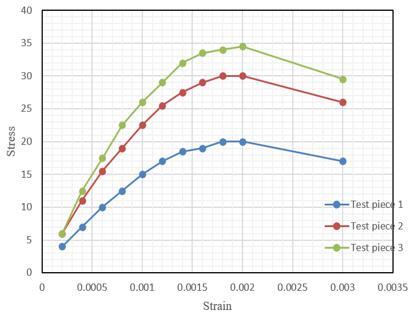
Figure 4 shows the stress performance of three bridge test pieces with different concrete strength in different strain conditions. By observing these data, it can be seen that Test piece 1 has the lowest concrete strength, and its stress value is also the lowest correspondingly. On the contrary, Test piece 3 has the highest concrete strength and its stress value is also the highest, which is in line with the expectations of a nonlinear model. That is, bridge test pieces with high material strength withstand higher stress in the same strain conditions. As shown in the figure, the stress of all test pieces shows a nonlinear increase as the strain increases, which once again proves the necessity of making nonlinear analysis. After the strain reaches 0.002, the stress of Test pieces 1, 2 and 3 begins to decrease, which is caused by cracks or other local failures. This phenomenon is more complex in nonlinear thermal-mechanical coupling conditions.
Figure 4. Constitutive relation of different bridge test pieces in nonlinear analysis
Figure 5. Load-displacement curves of bridge test pieces at different temperatures
Figure 5 shows the load-displacement relationship of bridge test pieces at different temperatures. As shown in the figure, the load capacity in the same displacement condition gradually decreases as the temperature increases, which is consistent with the expectations of thermal-mechanical coupling. That is, the strength and bearing capacity of materials decrease as the temperature increases. As the displacement increases, the load first increases but eventually approaches saturation in all temperature conditions, which means that structures have reached their ultimate bearing capacity, or there has been some form of failure or cracking. Further analysis shows that the load-displacement relationship of bridge test pieces is significantly affected by temperature. As the temperature increases, the maximum bearing capacity in the same displacement condition decreases. Therefore, the bearing capacity weakens when temperature increases, which requires special attention in bridge design and maintenance.
Figure 6. Bridge load/displacement-temperature analysis diagram
Figure 6 shows the ultimate bearing capacity and corresponding displacement value of a bridge at different temperatures. As shown in the figure, the ultimate bearing capacity of the bridge shows a downward trend with the increase of temperature, which is consistent with the conclusion drawn from the previous nonlinear thermal-mechanical coupling analysis. That is, an increase in temperature leads to a decrease in material properties, thereby affecting the bearing capacity of structures. Compared with the ultimate bearing capacity, the corresponding displacement value seems to have a slight positive correlation with the increase in temperature, because materials are more prone to deformation at higher temperatures, leading to greater displacement to reach the limit state. Therefore, it can be concluded that the ultimate bearing capacity and corresponding displacement value of the bridge exhibit a significant variation trend at different temperatures, especially the ultimate bearing capacity decreases with the increase of temperature. These findings emphasize the importance of nonlinear thermal-mechanical coupling analysis in the durability and safety assessment of bridge structures. This analysis method provides an effective tool especially in climate change and extreme temperature conditions.
Table 1. Ultimate bearing capacity and displacement of bridge test pieces in different strength conditions
|
Strength |
Test Piece 1 |
Test Piece 2 |
Test Piece 3 |
Test Piece 4 |
|
Ultimate Bearing Capacity (kN) |
86.3 |
101.8 |
1.9.6 |
124.6 |
|
Corresponding Displacement Value (mm) |
16.8 |
18 |
21.4 |
22.8 |
Table 1 shows that the ultimate bearing capacity of bridge test pieces varies in different strength conditions. As the strength increases (from Test piece 1 to Test piece 4), the ultimate bearing capacity also significantly increases, which is consistent with the theoretical expectations, i.e., structures with higher material strength should have higher bearing capacity. Compared with the ultimate bearing capacity, the corresponding displacement value also increases with the increase of strength (from 16.8mm to 22.8mm), meaning that structures with higher strength tolerate greater displacement before reaching their ultimate bearing capacity, which is usually a good index indicating that structures have better ductility. It can be concluded that the strength of bridge test pieces is positively correlated with their ultimate bearing capacity and corresponding displacement value. Higher strength not only provides higher bearing capacity, but also allows for greater displacement in limiting conditions. From the perspective of nonlinear thermal-mechanical coupling analysis, bridge test pieces with different strength require different analysis and design methods to ensure their performance and safety in various working conditions (including temperature changes).
Figure 7. Load-displacement curves of bridge test pieces in different strength conditions
As shown in Figure 7, the load of all test pieces increases accordingly as the displacement increases, which is nonlinear behavior in line with the expectations. When certain displacement is reached, the load of all test pieces tends to stabilize, i.e., reaching their limit value, which indicates that the test pieces begin to enter the plastic stage after this point, and the increase of displacement no longer significantly increases the load. Test pieces with higher strength (from Test piece 1 to Test piece 4) have higher ultimate load, which is consistent with the previous analysis, i.e., higher material strength usually leads to higher ultimate load. Test pieces with higher strength also withstand a larger displacement range, which means that high-strength materials not only have high bearing capacity, but also have good ductility. Therefore, it can be concluded that the load and displacement of bridge test pieces exhibit a nonlinear relationship in different strength conditions. Test pieces with higher strength have higher ultimate load and a larger displacement tolerance range. The load of all test pieces tends to stabilize after certain displacement has been reached, which is a sign of entering the plastic stage.
Table 2. Ultimate bearing capacity and displacement of bridge test pieces with different prestress sizes
|
Prestress Size |
700 |
800 |
900 |
1,000 |
1,100 |
|
Ultimate Bearing Capacity (kN) |
105.9 |
106.05 |
107.4 |
108.3 |
111.4 |
|
Corresponding Displacement Value (mm) |
21.8 |
22.4 |
21.2 |
22.3 |
18.9 |
It can be seen from Table 2 that the ultimate bearing capacity generally shows an upward trend as the prestress increases from 700MPa to 1,100MPa, which is in line with expectations, because higher prestress typically increases the overall bearing capacity of structures. In most cases, the corresponding displacement value slightly increases with the increase of prestress, indicating that structures exhibit a larger elastic range in the limit state. However, the corresponding displacement value decreases to 18.9mm when the prestress is 1,100MPa, because the higher prestress introduces more nonlinear effects or local failures. Therefore, it can be concluded that higher prestress generally improves the ultimate bearing capacity of bridge test pieces, but it also leads to more complex nonlinear behavior, which requires special attention in design and analysis. Bridge test pieces may exhibit unusual behavior in certain high prestress conditions, which is the result of nonlinear effects, changes in material properties, or other complex factors.
Figure 8. Load-displacement curves of bridge test pieces with different prestress sizes
As shown in Figure 8, the load with the same displacement value increases accordingly as the prestress increases from 700MPa to 1,100MPa, which is in line with expectations, because higher prestress typically increases the bearing capacity of structures. Similar to the load, test pieces with high prestress exhibit smaller displacement in the same load condition, which means higher stiffness. As the displacement increases, the growth rate of load at all prestress levels begins to slow down until it stabilizes, which means that structures have entered the plastic stage. When the displacement increases to 30 in the conditions of 1,000MPa and 1,100MPa prestress, the load value slightly decreases, which is caused by excessive stress or other nonlinear effects. Therefore, it can be concluded that high prestress level improves the bearing capacity and stiffness of bridge test pieces, but it also increases the complexity of nonlinear behavior, especially in the limit state. The load tends to stabilize after the displacement reaches a certain range, which is a sign that structures have entered the plastic stage.
Table 3. Ultimate bearing capacity and displacement of bridge test pieces with different corrugated steel web thicknesses
|
Thickness of Corrugated Steel Web |
3 |
4 |
5 |
6 |
7 |
|
Ultimate Bearing Capacity (kN) |
109.5 |
154.2 |
228.6 |
289.1 |
389.5 |
|
Corresponding Displacement Value (mm) |
21.5 |
23.9 |
24.6 |
25.9 |
33.7 |
It can be seen from Table 3 that the ultimate bearing capacity significantly increases as the thickness of the corrugated steel web increases from 3mm to 7mm, which is in line with expectations, because thicker corrugated steel web provides higher strength and stiffness, thereby increasing the overall bearing capacity of structures. As the web thickness increases, the displacement value in the limit state also increases correspondingly. However, when the web thickness is 7mm, the increase in displacement (from 25.9mm to 33.7mm) is relatively greater, which indicates that structures exhibit more plastic behavior or local failure modes when the corrugated steel web reaches a certain thickness. Considering that the previous discussion involves multiple factors, such as temperature, prestress, and material strength, the thickness of the corrugated steel web resulting from the interaction of these factors also generates complex nonlinear effects. Therefore, it can be concluded that thicker corrugated steel web significantly improves the ultimate bearing capacity of bridge test pieces due to higher strength and stiffness. Due to increased plastic behavior or other nonlinear effects, thicker corrugated steel web increases the displacement range of structures in the limit state, especially when the web is thicker (e.g., 7mm).
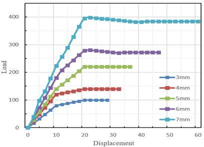
Figure 9. Load-displacement curves of bridge test pieces with different corrugated steel web thicknesses
It can be clearly seen from Figure 9 that the corresponding load also increases as the thickness of the corrugated steel web increases, because thicker web provides higher strength and stiffness. As shown in the figure, all test pieces have reached the limit state at a certain point. The displacement of this point increases with the increase of the web thickness, and significantly increases especially when the web thickness is 7mm. It is worth noting that the test pieces exhibit post-peak behavior after reaching the ultimate load, i.e., the load slightly decreases, when the web thicknesses are 5mm, 6mm and 7mm, indicating that these test pieces still maintain certain bearing capacity after the limit state. Due to plastic flow or local failure of materials, the load-displacement curve exhibits significant nonlinear characteristics especially when the web thickness is 7mm. Therefore, it can be concluded that the thickness of the corrugated steel web has a significant impact on the load-displacement relationship of bridge test pieces. The thicker web not only improves the ultimate bearing capacity of test pieces, but also increases the displacement in the limit state. When the web is thicker (i.e., 5mm and above), the test pieces exhibit certain post-peak behavior after reaching the ultimate load, which may mean that structures have better ductility in these conditions. When the web thickness is 7mm, the load-displacement relationship of bridge test pieces exhibits nonlinear characteristics, which requires special analysis and design considerations to ensure the safety and reliability of structures.
This study introduced a new thermodynamic model considering climate change factors, and focused on two main aspects: calculation of the shear bearing capacity of bridge oblique sections under the action of thermal-mechanical coupling, and nonlinear thermal-mechanical coupling calculation of bridges. The study discussed in detail how multiple factors, such as temperature, prestress, and material strength, affected the bearing capacity of bridge oblique sections. The new model took into account climate change factors, which made the bearing capacity calculation of bridges at different temperatures more accurate. Under certain specific corrugated steel web thickness and prestress, experimental data showed significant nonlinear behavior. Some test pieces still exhibited certain bearing capacity after reaching their peak, indicating certain ductility of structures in the limit state.
The following conclusions were drawn in this study:
First, multi-factor influence. The shear bearing capacity of bridge oblique sections was comprehensively influenced by multiple factors, such as temperature, prestress, material strength, and thickness of the corrugated steel web.
Second, importance of climate change. Consideration of climate change factors is crucial for more accurately estimating the long-term performance and safety of bridges. The new model described this more accurately through thermal-mechanical coupling.
Third, nonlinearity and ductility. Both experimental results and model calculations showed that structures may exhibit nonlinear and/or post-peak behavior in certain conditions. These characteristics require special consideration in structural design to ensure safety and reliability.
Fourth, universality and limitations of the model. Although the new model performed well in some aspects, whether it is applicable to all types of bridges and various environmental conditions still needs further verification.
Finally, engineering application and future research. Although the new model and experimental results provide important guidance for bridge engineering, further research is needed to optimize the design and evaluation methods, and more influencing factors need to be considered.
[1] Dai, Y., Jiang, H., Zhao, X., Tian, J., Deng, X., Zhang, W. (2023). A temperature-stable Pd nanofilm hydrogen sensor with a Wheatstone bridge structure. Journal of Materials Science: Materials in Electronics, 34(9): 833. https://doi.org/10.1007/s10854-023-10219-x
[2] Bai, X., Liu, Z., Lv, H., Chen, J., Khan, M., Wang, J., Sun, B.H., Shi, K. (2022). N-doped three-dimensional needle-like CoS2 bridge connection Co3O4 core–shell structure as high-efficiency room temperature NO2 gas sensor. Journal of Hazardous Materials, 423: 127120. https://doi.org/10.1016/j.jhazmat.2021.127120
[3] Yuan, Y. (2023). Natural frequency analysis of beam bridge structure under temperature and vehicle action. Jilin Daxue Xuebao (Gongxueban)/Journal of Jilin University (Engineering and Technology Edition), 53(6): 1702-1710.
[4] Wang, Y., Hou, Y., Yu, X., Zheng, M., Zhu, M. (2021). Intergranular particle bridge structure design strategy boosts high-temperature energy harvesting performance of fine-grained ceramics. ACS Applied Electronic Materials, 3(12): 5496-5505. https://doi.org/10.1021/acsaelm.1c00926
[5] Hou, Q., Li, Q., Zou, L., Sun, Y., Liu, Q. (2022). A combined-constraints-based optimization methodology aimed at temperature balancing for radial layered encapsulation structure of bridge arm reactor. IET Generation, Transmission & Distribution, 16(20): 4176-4186. https://doi.org/10.1049/gtd2.12589
[6] Hou, B., Zhao, W., Gao, L., Cai, X., Qie, L., Xu, Y. (2022). Study on temperature adaptability of track structure in railway bridge-tunnel transition area in complex and difficult mountainous areas. Tiedao Xuebao/Journal of the China Railway Society, 44(5): 119-126.
[7] Zhou, L., Zhang, G., Yu, Z., Zhao, L., Wei, T., Yang, L. (2020). Model experiments of ballastless track-bridge structure under cyclic temperature load. Tiedao Xuebao/Journal of the China Railway Society, 42(1): 82-88.
[8] Peng, L., Jing, G., Luo, Z., Yuan, X., Wang, Y., Zhang, B. (2020). Temperature and strain correlation of bridge parallel structure based on vibrating wire strain sensor. Sensors, 20(3): 658. https://doi.org/10.3390/s20030658
[9] Gao, T., Wang, X., Zhao, J., Jiang, P., Jiang, F.L., Liu, Y. (2020). Bridge between temperature and light: bottom-up synthetic route to structure-defined graphene quantum dots as a temperature probe in vitro and in cells. ACS Applied Materials & Interfaces, 12(19): 22002-22011. https://doi.org/10.1021/acsami.0c02500
[10] Huang, M., Lei, Y., Cheng, S. (2019). Damage identification of bridge structure considering temperature variations based on particle swarm optimization-cuckoo search algorithm. Advances in Structural Engineering, 22(15): 3262-3276. https://doi.org/10.1177/1369433219861728
[11] Verma, M., Mishra, S.S. (2020). Temperature-driven fatigue life of reinforced concrete integral bridge pile considering nonlinear soil-structure interaction. Structural Concrete, 21(6): 2565-2583. https://doi.org/10.1002/suco.202000049
[12] Sun, Y.Q., Zhao, Z.Z. (2019). Real-time seperation of temperature effect on dynamic strain monitoring and moving load identification of bridge structure. Gongcheng Lixue/Engineering Mechanics, 36(2): 186-194. https://doi.org/10.6052/j.issn.1000-4750.2017.12.0954
[13] Li, M., Zhong, J.W., Yan, F. (2018). Correlation analysis between structure temperature and deflection of a suspension bridge girder. Journal of Vibration and Shock, 37(11): 237-245.
[14] Cai, Q., Xu, R.J., Chen, C.B., Mo, H.B., Lei, C.H., Li, L.B., Li, Z.H. (2015). Influence of annealing temperature on the lamellar and connecting bridge structure of stretched polypropylene microporous membrane. Polymer International, 64(3): 446-452. https://doi.org/10.1002/pi.4828
[15] Wang, J., Li, W., Gou, J., Wu, Z., Jiang, Y. (2015). Fabrication and parameters calculation of room temperature terahertz detector with micro-bridge structure. Journal of Infrared, Millimeter, and Terahertz Waves, 36: 49-59. https://doi.org/10.1007/s10762-014-0120-x
[16] Xie, D., Cai, G., Liu, Z., Guo, R., Sun, D., Zhang, C., Wan, Y., Peng, J., Jiang, H. (2016). The low temperature electrochemical performances of LiFePO4/C/graphene nanofiber with 3D-bridge network structure. Electrochimica Acta, 217: 62-72. https://doi.org/10.1016/j.electacta.2016.09.058
[17] Li, G.P., Hu, H., Ren, C., Zhou, S.Y., Li, J.X. (2018). Study on durability of joints in concrete bridge structures. China Civil Engineering Journal, 51(7): 98-103.
[18] Khan, H. (2019). The corrosion conundrum: Durability risks and protection to bridge structures. Highway Engineering Australia, 50(5): 52-56.
[19] Wang, W., Myers, J.J. (2016). durability assessment of FRP bars extracted from existing FRP bridge structures exposed to field conditions. In Proceedings of the 8th International Conference on Fibre-Reinforced Polymer (FRP) Composites in Civil Engineering, CICE 2016, Hong Kong, pp. 887-892.
[20] Wan, T.B. (2016). Performance requirements of viscous dampers for improvement of durability of bridge structures. Bridge construction, 46(4): 29-34.
[21] Keller, T., Theodorou, N.A., Vassilopoulos, A.P., De Castro, J. (2016). Effect of natural weathering on durability of pultruded glass fiber–reinforced bridge and building structures. Journal of Composites for Construction, 20(1): 04015025. https://doi.org/10.1061/(ASCE)CC.1943-5614.0000589
[22] Tabata, A., Yamaguchi, T. (2014). Study on applicability of high durability friction grip joints with high strength countersunk head bolts for steel bridge structures. Faculty of Engineering.