Murtada A. Ismael*![]() | Haitham Jameel Abd
| Haitham Jameel Abd![]() | Suha Rasheed Abbas
| Suha Rasheed Abbas![]()
© 2023 IIETA. This article is published by IIETA and is licensed under the CC BY 4.0 license (http://creativecommons.org/licenses/by/4.0/).
OPEN ACCESS
In this study, an innovative reinforcement technique is proposed to augment the structural performance of reinforced concrete (RC) columns. The technique involves the introduction of inclined steel ties (bracing reinforcement), connecting longitudinal steel rebars on one side of the square column cross-section at a tie with the longitudinal rebar on the opposite side at the next lower tie. These inclined ties form with the conventional ties and longitudinal rebars a truss structure. The introduced bracing reinforcement effectively enhances the bracing of longitudinal rebars, resulting in substantial improvements in the strength and ductility of RC columns. The study investigates three key parameters using finite element analysis: the pattern of bracing reinforcement, the number of bracings along the column height, and the application of bracing reinforcement under eccentric loading conditions. The findings demonstrate a significant enhancement in yield and ultimate load, stiffness, and ductility of RC columns utilizing this novel technique. Specifically, employing two bracing reinforcements on opposing sides of the column yields the most remarkable structural performance improvement, manifesting in a 32.2% increase in yield load, a 38.7% increase in ultimate load, and a 60.7% augmentation in ductility ratio. Moreover, the study reveals a proportional increase in structural performance improvement with an escalation in the number of bracings within the column height. However, when employing bracing reinforcement under eccentric loading, a reduction in the gain of ultimate strength and ductility, and a corresponding rise in the gain of yield load are observed in comparison to concentric loading conditions.
bracing, column concrete, finite-element reinforcement, structural
Columns can be defined as the structural elements that support loads mainly in compression. They are usually reinforced with longitudinal bars as the main reinforcement to resist the compression loads and lateral reinforcement transverse to the longitudinal bars which fix the longitudinal bars in their position in the molds and provide confinement to the longitudinal bars to prohibit longitudinal bars from buckling due to high stresses which causing the concrete cover to be pushed outward [1-4]. However, this ideal function condition for longitudinal and lateral reinforcing steel is difficult to achieve, especially when the columns are subjected to eccentric loads or for the columns subjected to lateral loads, where bending moments arise around one or both cross-sectional axes producing tensile forces in one side and compressive forces in the other side, this leads to the occurrence of irregular stresses within the cross-section of the column resulting in early failure [5-7].
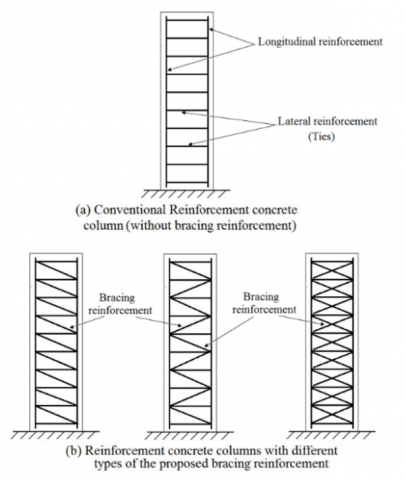
On the other hand, with the increasing demand for the erection of high-rise structures, the structural elements that consist of these buildings require to have high strength with efficient mechanical properties. The column is one of the most crucial structural elements that play an essential part in transporting vertical and transverse loads, especially on the lower floors since it experiences high vertical loads [8-10], also the philosophy of building design requires that the failure should occur in beams before columns (weak beam-strong column theory) [11]. This necessitates finding new techniques that improve structural performance in regard to strength, stiffness, and ductility, especially in areas exposed to seismic activity. In this paper, a new technique has been proposed to enhancement the structural performance of reinforced concrete (RC) columns, it is proposed to use bracing reinforcement represented by inclined steel ties linking the longitudinal steel rebars on the side of the square cross-section with the opposite side in the lower tie, these bracings with the ties form reinforcement like a spiral in circular section column in addition to its ability to support the longitudinal reinforcement. Figure 1 illustrates a RC column with conventional reinforcement (without bracing reinforcement) and RC columns with bracing reinforcement. These bracings redistribute the stresses in the column, prevent the concentration of stresses in particular regions, reduce the local buckling by providing additional confinement, increase the strength and ductility, and avoid the column's early failure, thus it improves the structural performance of RC columns.
In the past two decades, a number of researches presented different methods to improve the structural performance of RC columns and their behavior under different circumstances. Zhou et al. [12] presented an empirical exploration on the attitude of RC columns having two types of circular spiral reinforcement being loaded axially and eccentrically. Their outcomes demonstrated that using circular and square spirals keeps more confinement in square RC columns exposed to axial and eccentric loading. The strength, ductility, and stiffness of columns with these types of reinforcement were enhanced.
Figure 1. (a) RC column with conventional reinforcement (without bracing reinforcement) (b) RC columns with different types of bracing reinforcement
Ayyasamy et al. [13] investigated empirically and numerically the performance of composite columns encased by steel. The investigation results revealed that the composite column encased by steel had more strength than the conventional RC column and I-steel column. Also, numerical outcomes revealed that the strain and stress variations along the column height displayed a pattern like that of the empirical investigation and the noted magnitudes showed the composite impact of the suggested steel-encased composite column in an acceptable manner.
Salman and Al-Sherrawi [14] presented an exploration on the attitude of RC columns with steel jackets in the pre-loading and post-loading (non-damaging) column stage. The results showed that the involvement of the steel jacket enhanced the strength of the column by raising the confinement of the concrete. The strengthening of the RC column within the pre-loading gives higher strength than the post-loading stage. Also, it was noticed that the residual stresses improve with raising the loading ratio of the column without a steel jacket. The residual strain and stress were significant as a loss in the initial strain and stress of reinforcing bars and concrete that caused a decrease in the strength.
Teng et al. [15] suggested an alternative method of the finite element method (FEM) to predict steel and (Fiber Reinforced Polymer) FRP-confined columns, as illustrated using comparisons to the empirical outcomes, the suggested approach is effective in presenting precise outcomes for steel and FRP-confined columns.
Karabinis et al. [16] used the FEM to study the structural attitude of RC columns with bars that had premature buckling under compressive loading with the impact of an external FRP jacket. It was found that even with a small ratio of FRP, the produced confinement could considerably enhance the performance of RC columns by supplying transverse constraint that prevents buckling of main reinforcement bars. Considering the findings of this investigation, the non-constraining of the main reinforcement bars against the deformation made the column ductility reduce to half.
Memar et al. [17] evaluated the attitude of columns reinforced by normal concrete and engineered cementitious composite jacketing. The results revealed that the employing of engineered cementitious composite rather than normal concrete may increase column bearing capacity, caused by the tensile strain hardening of this material and the magnitude of this increase based on loading eccentricity. Also, found that in concrete jacketing, the cracks were scattered and had a further amount of damage while in engineered cementitious composite jacketing, the cracks were continuous.
Prasetyo et al. [18] presented a numerical exploration on the attitude of RC column of steel and glass fiber reinforced polymer (GFRP) bars in high strength concrete stage. Since the uniaxial attitude of the GFRP bar changes considerably from compression to tension as it is employed as the main reinforcement, the outcomes revealed that only 25% under compression and 45% under the tension of the yield value of the GFRP bar can be employed.
Belal et al. [19] investigated the strengthening of RC columns using the jacket of steel. Three parameters were studied; strengthening pattern (angles, C-sections, and plates), number, and size of the jacket. The outcomes detected that all the patterns of strengthening had a significant effect on the column strength. Also, they concluded that for specimens supplemented with an angle pattern, the size of the jacket significantly affected the ultimate load, but for specimens reinforced with a C-section, the number of plates had a greater impact.
By reviewing previous research and studies that dealt with the issue of strengthening and developing the performance of RC columns, it can be found that the technique proposed in the current research represented by using bracing reinforcement to enhance the structural performance of RC columns has not been used in any of the previous research. Therefore, this research aims to explore numerically the use of bracing reinforcement in the enhancement of the structural performance of RC columns in regard to column strength and ductility utilizing the ABAQUS program. The bracing reinforcement that is used in this exploration is represented by inclined steel ties linking the longitudinal steel rebars on the side of the square column cross-section with the opposite side in the lower tie. These bracings contribute to the ties in forming reinforcement like a spiral in the circular section column. The exploration of this paper includes two stages, in the first stage a verification study is achieved to examine the validity and accuracy of the numerical models of RC column, while in the second stage, three parameters are studied involving; bracing reinforcement pattern, number of bracings within the column height, and using bracing reinforcement under eccentric loading.
In this paper, the research plan included two parts: in the first part, the validity and accuracy of the numerically prepared column model using the nonlinear FEM is investigated by modeling the column that is established in a previous study and comparing the numerical results with the empirical results. In the second part, the effect of a number of parameters on the performance of RC columns is studied.
2.1 Verification study
2.1.1 Finite element modeling
In this part of the research plan, the column of the previous study presented by Belal et al. [19] was selected and simulated numerically using FEM, and its results were compared with the published results. The column specimen has a square cross-section of 200×200mm and 1200mm in height. The steel reinforcement is 4Ø12 as longitudinal steel and 6Ø8 as a stirrup with 360 MPa and 240 MPa yield stress respectively. While the concrete has a cubic compressive strength of 34MPa. Figure 2 demonstrates the column dimensions and details of steel reinforcement.
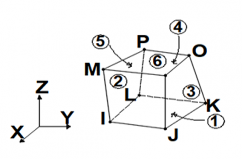
The elements that were used to model concrete and steel rebars were selected from the element library of the ABAQUS software, according to the characteristics of each element and their ability to simulate the behavior of the material. However, according to the Abaqus Analysis User's Manual [20], the RC column can be modeled by an eight-node solid (brick) element, which is identified in ABAQUS as a C3D8R with reduced integration following the constitutive law integration accurately. This element is very suitable for nonlinear static analyses. Each node in a solid element can translate freely in three dimensions, across all three axes x, y, and z. As the element material fails in three orthogonal directions, plastic deformation can take place. Node positions and geometry of this element are demonstrated in Figure 3 [20].
Figure 2. Column dimensions and details of steel reinforcement investigated by Belal et al. [19]
Figure 3. Geometry and node positions of C3D8R element [20]
The longitudinal and lateral reinforcement steel bars are modeled by a first-order, three-dimensional, and two-nodded beam element embedded in concrete block B31. The element B31 has the ability to resist stresses in the direction along its axis and it is compatible with the concrete element C3D8R in regard to its degree of freedom in each node [20]. The column models discretize a number of elements that permit getting close results as compared with the empirical results. Figure 4 illustrates the FE model of the column, the constrained state, and loading.
Figure 4. The FE model of the column
The global coordinate system of the column models was appointed in which the bottom base of the column lies in the x-z plane and the y-axis is oriented to the axis of the columns. The bottom face of the column was completely fixed (zero displacements and rotations on all nodes). A vertical load was applied on the top face of the columns as shown in Figure 4. The load was subdivided into several steps in which it increased gradually with a constant rate from zero to the final load. The models were achieved using (the criterion of force convergence) with a tolerance of (5%), and the full Newton-Raphson method was used as a nonlinear solution algorithm.
2.1.2 Failure criteria of concrete
ABAQUS adopts a constitutive model of damaged plasticity as a failure criterion for concrete. This failure criterion presents a general ability for simulating concrete and other materials that behave quasi-brittle in all kinds of structural elements and employ principles of isotropic damaged elasticity associated with compressive plasticity and isotropic tensile to model the plasticity attitude of concrete [20, 21].
2.1.3 Outcomes of the verification study
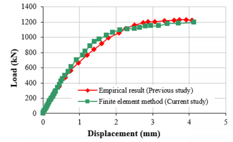
The load-displacement relationship at a node in the middle height of the column was determined from the FE exploration accompanied by the empirical curve obtained by Belal et al. [19] is displayed and contrasted in Figure 5. The figure exhibits good correspondence between the FE and empirical curves. Table 1 illustrates that the ultimate load determined by the FEM is marginally lower than the ultimate empirical load of the RC column with a percentage of 2.2%, while the ultimate displacement of the FEM is slightly larger than the ultimate empirical displacement by 1.2%. The difference between the empirical and the FEM results of the current study can be attributed to the approximate nature of the FE analysis that belongs to many reasons such as the approximation inherent in the FE technique that is established on the transfer of the continuum to a finite number of elements, thus the accuracy increases with increase the element number but this leads to consumption more efforts and time. Also, the FEM is based on approximations: the modeling of materials such as concrete and steel, representation of the failure criterion, approximation in the function of integration employed in this FEM, and approximation on the process utilized to deal with the equations in the nonlinear domain. However, it is evident that the differences between the empirical results and the results of the FEM of this study are negligible differences, and this proves that the representation using all the above approximations is efficient and the FE models are employable to explore the variables of this research.
Table 1. Empirical [19] and FE analysis results of ultimate load and ultimate displacement
|
PFEM(kN) |
PE(kN) |
∆FEM(mm) |
∆E(mm) |
(PFEM/PE)×100(%) |
(∆FEM/∆E)×100(%) |
|
1195 |
1222 |
4.13 |
4.08 |
97.8 |
101.2 |
Figure 5. Empirical [19] and FE analysis of load-displacement curves of the column
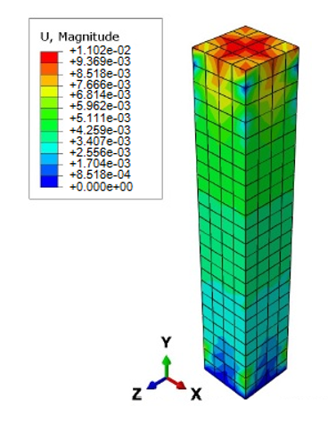
Figure 6. Axial displacement contour at the ultimate load for the column using ABAQUS
Belal et al. [19] used ANSYS software to investigate numerically the attitude of the columns reinforced with steel jackets after examining the columns empirically. The results of their study regarding the model that was used in this current study showed that the differences between the theoretical study and the practical study were about 3% for the ultimate load, as well as 3% for the ultimate displacement, it is clear that of the outcomes of the current study are closer to the empirical results, and this is due to the fact that the current study used numerical representations that were closer to empirical behavior.
Figure 6 shows the Axial displacement contour at the ultimate load for the column using ABAQUS. This figure reveals that the contour distribution of the displacements is highest in the upper face of the column under load directly due to the high stresses and decreases towards the base of the column.
2.2 Parametric study
In this section, a parametric study is achieved to explore the impact of the most important parameters on the structural performance of RC columns with bracing reinforcement. The numerical column model that was used in the previous section (verification study) was used in the parametric study after adding bracing reinforcement of 8mm diameter to it in different forms based on the studied parameter. The parameters include bracing pattern, the number of bracings within the column height, and loading eccentricity.
2.2.1 Impact of the bracing pattern
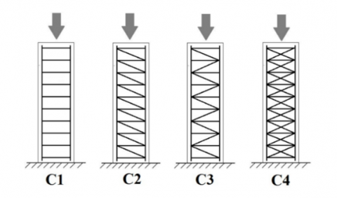
To study the impact of the bracing reinforcement pattern on the structural behavior of RC columns, four columns were used as shown in Figure 7, the first specimen represents the reference of conventional reinforcement (without bracing reinforcement) (C1), the second has one bracing in the space between every two consecutive ties inclined from one side (C2), the third has one bracing in the space between every two consecutive ties inclined from two sides (C3), while the fourth has two opposite bracings in the space between every two consecutive ties (C4).
Figure 7. Column specimens with conventional reinforcement (C1) and column specimens with different bracing patterns (C2 to C4)
Table 2 lists the numerical results of the impact of the bracing pattern on the structural behavior of RC columns in regard to longitudinal steel yielding load (Py), ultimate load (Pu), displacement at yield (∆y), ultimate displacement (∆ult), and the ductility ratio (∆ult/(∆y). It can be noticed that in general using bracing reinforcement in all the different patterns results in an increase in the yield and ultimate load but the impact on the ultimate load is more significant. However, using one bracing inclined from one side (C2) makes the yield load increase by a percentage of 13.9% and the ultimate load by 24.3%, while using one bracing inclined from two sides (C3) raises the yield load by 22.4% and ultimate load by 31.2%, so the second pattern of bracing is more efficient than the first in improving the structural performance of RC columns, the reason of that difference can be explained in the fact that the second pattern makes the stress redistribution more uniform within the column than the first pattern, on the other side, the third pattern of two opposite bracings (C4) reveals that it is the best in regard to improving structural performance as it leads to an increase in yield load by 32.2% and ultimate load by 38.7%.
Table 2. Impact of bracing pattern on the structural behavior of RC columns
|
Col. |
Py(kN) |
Change in Py(%) |
Pult(kN) |
Change in Pult(%) |
∆y(mm) |
∆ult(mm) |
Ductility Ratio(∆ult/(∆y) |
Change in Ductility Ratio(%) |
|
C1 |
972 |
- |
1195 |
- |
1.53 |
4.13 |
2.699 |
- |
|
C2 |
1107 |
13.9 |
1485 |
24.3 |
1.49 |
5.33 |
3.577 |
32.5 |
|
C3 |
1190 |
22.4 |
1568 |
31.2 |
1.49 |
5.51 |
3.698 |
37.0 |
|
C4 |
1285 |
32.2 |
1657 |
38.7 |
1.42 |
6.15 |
4.331 |
60.7 |
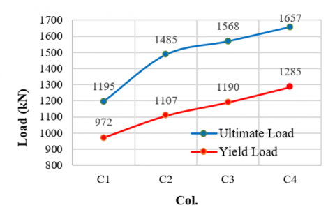
Figure 8 also reveals that the improvement in the yield load when using the bracing reinforcement is with an approximately constant slope, while the improvement in the ultimate loads is with a steeper slope when using the bracing reinforcement, then it becomes somewhat with a constant slope. The explanation for this behavior belongs to the fact that the reinforcement is effective as soon as the longitudinal reinforcement suffers from yielding deformation as the bracing reinforcement retains the longitudinal reinforcement in place and provides more confinement with the lateral reinforcement before the failure of the column.
Figure 8. Impact of bracing pattern on yield and ultimate load of RC columns
On the other side, the load-displacement relationships of the reference specimen (C1) and column specimens with different bracing patterns (C2 to C4) are shown in Figure 9. It can be noted that in general, the presence of the bracing reinforcement makes the stiffness of the column increase with all the different bracing patterns, as at a particular load level, the displacement decreases at all stages of loading, and the impact of bracing is very slight before the yield load and increases after that to be significant, this behavior can be attributed to the same reason mentioned above in explanation the improvement on yield and ultimate loads using bracing reinforcement. Also, it can be found that a column of two opposite bracings (C4) has the largest stiffness, followed by a column of one bracing inclined from two sides (C3), then the column of one bracing inclined from one side (C2).
At the same time, Table 2 and Figure 10 reveal that using the bracing reinforcement leads to an improvement in ductility, as the ductility increases with percentages of 32.5%, 37.0%, and 60.7% respectively for the column with bracing reinforcement C2, C3, and C4. The reason for these increases in ductility can be attributed to that the bracing reinforcement retransmits the stresses uniformly to the concrete of the column, raising the confinement of the concrete resulting in more bearing capacity which maintains the column integrity making it withstand greater load and exhibits more deformation before failure. The increase in ductility is very necessary for structural elements as it makes concrete exhibit warning before failure and prevents sudden collapse [22].
Figure 9. Impact of bracing pattern on load-displacement relationship of RC columns
Figure 10. Impact of bracing pattern on ductility ratio of RC columns
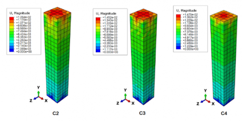
Figure 11 shows that the axial displacement contour at ultimate load in columns C2, C3, and C4 using ABAQUS are similar to that of C1 in Figure 7 but the values of displacement at failure increase with the use of bracing reinforcement according to the bracing pattern.
Figure 11. Axial displacement contour at the ultimate load of column C2, C3 and C4 using ABAQUS
2.2.2 Impact of the number of bracings within the column height
Four columns were used to study the impact of a number of bracings within the column height on the structural behavior of RC columns as shown in Figure 12, the first specimen represents the reference column without bracing reinforcement (C1), the second has two opposite bracings in three levels (C5), the third has two opposite bracings bracing in five levels (C6), while the fourth has two opposite bracings bracing in nine levels (C4).
Figure 12. Column specimen with conventional reinforcement (C1), column specimen with bracings in three levels (C5), five levels (C6) and nine levels (C4)
Table 3. Impact of bracing number on the structural behavior of RC columns
|
Col. |
Py(kN) |
Change in Py(%) |
Pult(kN) |
Changein Pult(%) |
∆y(mm) |
∆ult(mm) |
Ductility Ratio(∆ult/(∆y) |
Change in Ductility Ratio(%) |
|
C1 |
972 |
- |
1195 |
- |
1.53 |
4.13 |
2.699 |
- |
|
C5 |
1105 |
13.7 |
1309 |
24.3 |
1.49 |
4.67 |
3.134 |
32.5 |
|
C6 |
1190 |
22.4 |
1379 |
31.2 |
1.49 |
5.05 |
3.389 |
37.0 |
|
C4 |
1285 |
32.2 |
1657 |
38.7 |
1.42 |
6.15 |
4.331 |
60.7 |
Table 3 lists the numerical results of the impact of bracing number on the structural performance of RC columns in regard to longitudinal steel yielding load (Py), ultimate load (Pu), displacement at yield (∆y), ultimate displacement (∆ult), and the ductility ratio (∆ult/(∆y). It can be noticed that in general using bracing reinforcement at any number of levels raises the yield and ultimate loads and the impact on ultimate loads is more obvious.
However, for the column with three levels of bracing the gain in the yield load is 13.7% and in the ultimate load is 24.3%, while the gains for the columns of five and nine levels are 22.4%, 31.2% and 32.2%, 38.7% respectively. Figure 13 also demonstrates that the enhancement in the yield load using the bracing reinforcement of three, five, and nine levels has an approximately linear tendency, while the enhancement in the ultimate loads starts with linear and ends with an abrupt ascent. Figure 14 illustrates the relationship between the load-displacement relationships of the reference specimen (C1) and column with different bracing numbers (three, five, and nine) in specimens (C5, C6, and C4) respectively. It is clear from the figure that at all stages of loading the displacement decreases as the number of bracing increases from three, five, and nine although the ultimate displacement increases with percentages 13.1%, 22.3%, and 48.9% respectively, resulting in an increase in the ductility with percentages 32.5%, 37.0% and 60.7% as demonstrated in Table 3 and Figure 15. Also, Figure 15 reveals that the relationship between the ductility ratio and the number of bracing appears approximately linear when using three and five bracings, and then there is a slight rise when using nine bracings. This can be explained by the fact that the use of bracing reinforcement at all levels is more efficient in redistributing stresses within the column, but when it is used in specific regions, the regions that do not have bracing will be weak regions that accelerate the failure of the column due to the concentration of stresses.
Figure 13. Impact of bracing pattern on yield and ultimate load of RC columns
Figure 14. Impact of bracing number within the column height on load-displacement relationship of RC columns
Figure 15. Impact of bracing level number on ductility ratio of RC columns
Figure 16 illustrates variations in the axial displacement at the ultimate load of columns C5 and C6 using ABAQUS. By comparing the contour distribution of the ultimate axial displacement of these two columns with each of the reference column specimen C1 (without bracing), as well as the column specimen that included fully bracing reinforcement within the levels of column C4 as shown in Figures 7 and 12 respectively, it can be noticed a difference in the contour distribution in the C5 and C6 columns, this can be attributed to that the presence of braced and unbraced regions within these columns leads to heterogeneity in the distribution of stresses, and thus the occurrence of differences in the distribution of ultimate displacements within the columns C5 and C6 compared to C1 and C4.
Figure 16. Axial displacement contour at the ultimate load of column C5 and C6 using ABAQUS
2.2.3 Impact of bracing reinforcement with eccentricity loading
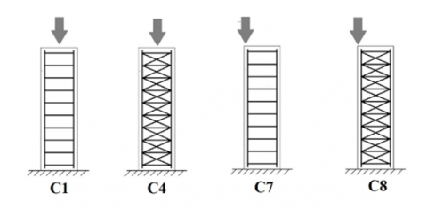
Figure 17. A column with conventional reinforcement under concentric loading (C1), a column with bracing reinforcement under concentric loading (C4), a column with conventional reinforcement under eccentric loading (C7), a column with bracing reinforcement under eccentric loading (C8)
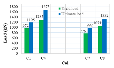
To explore the impact of using bracing reinforcement on the reinforced columns subjected to eccentric loading, two column specimens were used, the first specimen without bracing reinforcement (C7) and the second has two opposite bracings in the space between every two consecutive ties (C8) these two columns are subjected to eccentric loading. The analysis results for these two specimens are compared with specimens C1 and C4 to find out the difference between the use of bracing reinforcement under eccentric loading and under concentric loading. Figure 17 shows the specimens used in studying this parameter.
Table 4 and Figure 18 illustrate the impact of bracing reinforcement on the yield and ultimate load of RC columns under eccentric and concentric loading. Generally, it is clear from these results that both the yield and ultimate loads increase with the use of bracing reinforcement under eccentric loading, and the impact on the yield load is greater than that on the ultimate load, and the latter behavior is contradictory to that of use the bracing reinforcement with the column subjected to concentric loading. This contradictory belongs to that under eccentric loading the redistribution of stresses within the column with bracing reinforcement delays the longitudinal steel yielding, which occurs early in the column without bracing due to the concentration of stresses on the side under the load being higher than the other far side, leading to early yielding comparing with the column without bracing under concentric loading which does not suffer from differences in stresses between the two sides of the cross-section where the stresses are uniformly distributed.
Figure 18. Impact of bracing reinforcement on the yield and ultimate load of RC columns subjected to concentric and eccentric loading
Also, Table 4 states that the gain in yield load of the column under eccentric loading due to using bracing reinforcement is more than that of the column subjected to the concentric loading but the gain in ultimate load is less. However, using two opposite bracings in the space between every two consecutive ties in the column subjected to the eccentric loading makes the yield load increase by 38.0% and the ultimate load by 34.3%, thus the gain in yield load is more than that of the column subjected to eccentric loading by 18.0% and less than the gain in the ultimate load by 11.4%. The reason why the ultimate load is less affected by bracing than yield loading under eccentric loading can be explained by that the yield load is related to the strength of reinforcing steel, while the ultimate load is related to the strength of reinforcing steel and the concrete together, and the efficiency of the bracing reinforcement under eccentric loading will be greater in transferring the stresses between the two sides of the column, but when the column reaches to ultimate load, the stresses in the concrete will vary greatly between the two sides of the column in which reinforcement has exceeded the yield stress, and therefore, the efficiency of the bracing reinforcement in raising the ultimate load will be less than that in the yield load.
Table 4. Impact of bracing reinforcement on the structural behavior of RC columns subjected to concentric and eccentric loading
|
Loading |
Col. |
Py(kN) |
Change in Py(%) |
Pult(kN) |
Change in Pult(%) |
∆y(mm) |
∆ult(mm) |
Ductility Ratio(∆ult/(∆y) |
Change in Ductility Ratio(%) |
|
Concentric Concentric |
C1 |
972 |
- |
1195 |
- |
1.53 |
4.13 |
2.699 |
- |
|
C4 |
1285 |
32.2 |
1657 |
38.7 |
1.42 |
6.15 |
4.331 |
60.7 |
|
|
Eccentric |
C7 |
776 |
- |
992 |
- |
1.45 |
3.52 |
2.427 |
- |
|
Eccentric |
C8 |
1071 |
38.0 |
1332 |
34.3 |
1.45 |
4.78 |
3.296 |
35.8 |
To compare the impact of using bracing reinforcement on the load-displacement relationship between a column subjected to eccentric loading with a column subjected to concentric loading, the relationship diagram was drawn as in Figure 19. This figure discloses that using bracing reinforcement enhances the stiffness of the column subjected to eccentric loading by decreasing the displacement at all loading stages, and the impact before yielding is less significant than after yielding, but the enhancement in the case of eccentric loading is less efficient than the case of concentric loading since it is evident from Table 4 that under eccentric loading, the ultimate displacement increases by 35.8% using the bracing reinforcement with maintain the displacement at yielding in a constant value, while the increase in the case of concentric loading is 48.9%. The stability of the displacement value at yield and the increase in its ultimate value leads to an increase in ductility by 35.8% but this improvement in the ductility is less than that in the case of concentric loading which is 60.7%, Figure 20 indicates the ductility ratio for the two cases.
Figure 21 shows the contour of the axial displacement at the ultimate load of columns C7 and C8, it is observed that the displacement in the side under the loads seems the largest compared to the other regions due to the stress concentration under loading, also it can be noted that C8 which has bracing reinforcement exhibits large displacement compared with the C7 which has conventional reinforcement (without bracing reinforcement) due to ability of column C8 to carry high loads.
The results of this study, which reveal the effect of using bracing reinforcement as a new proposed technique, on the enhancement of the structural performance of short RC columns with square sections in regard to the strength and ductility, are consistent with the use of spiral reinforcement in columns with circular sections [1-2, 5, 23-25] as well as the results of using spiral reinforcement in columns with square sections as obtained by Zhou et al. [12], Mesa-Lavista et al. [26], Shih et al. [27], Chen et al. [28] and Ou et al. [29], since these studies revealed that the strength and ductility of RC columns improve with the use of spiral reinforcement and under different loading conditions (the presence of lateral loading or eccentric loading). The technique proposed in the current study is similar to using spiral reinforcement in providing confinement on concrete, but it differs from it in that the bracing reinforcement technique forms a truss with ties and longitudinal rebars that is more efficient than spiral reinforcement in redistributing stresses inside the column and preventing their concentration in specific regions, which makes it more efficient in enhancement the performance of short RC columns, this is evident from the outcomes of the current study.
Figure 19. Impact of bracing reinforcement on the load-displacement relationship of RC columns under eccentric and concentric loading
Figure 20. Impact of bracing reinforcement on the ductility ratio of RC columns under eccentric and concentric loading
Figure 21. Axial displacement contour at the ultimete load of column C7 and C8 using ABAQUS
In this paper a new technique has been proposed to enhancement the structural performance of RC columns by using bracing reinforcement linking the longitudinal steel rebars on a side of the square column cross-section with the opposite side in the lower tie, these bracings contribute to the ties to form reinforcement like a spiral in circular section column in addition to its ability to bracing the longitudinal reinforcement. Three parameters were studied involving; bracing reinforcement pattern, number of bracings within the column height, and using bracing reinforcement under eccentric loading. It can be concluded from the results that:
1. The proposed technique of using bracing reinforcement is an efficient technique in improving the structural performance of RC columns by increasing yield and ultimate loads, as well as increasing the stiffness by reducing displacement in all stages of loading and increasing ductility compared to columns without bracing reinforcement.
2. With regard to the RC column stiffness represented by the load-displacement relationship, the effectiveness of this proposed technique is slight before the yield load and becomes significant after that until the ultimate load.
3. Using two opposite bracings in the space between every two consecutive ties reveals that it is the best technique in regard to improving the structural performance in regard to yield load, ultimate load, column stiffness, and ductility compared to using one bracing inclined from one side and one bracing inclined from two sides in the space between every two consecutive ties. Using one bracing inclined from one side is less efficient among the three patterns of the proposed technique.
4. The efficiency of the proposed technique in improving the structural performance increases with the increase in the bracing number within the height of the column.
5. The increase in ultimate load and ductility is less pronounced in the case of using bracing reinforcement for columns subjected to eccentric loading and the increase in ultimate load and ductility is more considerable compared to that obtained when using the proposed technique with columns under concentric loading.
6. The efficiency of the proposed technique in enhancing the strength and ductility of RC columns provides the possibility of using it in regions that require columns with high strength and ductility, such as high-rise buildings, especially in areas subject to seismic loads.
For future works, the technique that is proposed in this research can be empirically studied, other variables can be studied such as changing the diameter of the bracing reinforcement, using this technique in columns with rectangular sections, studying its effect under seismic loads, and studying its effect within thin columns.
|
FEM |
Finite Element Method |
|
FE |
Finite Element |
|
FRP |
Fiber Reinforced Polymer |
|
GFRP |
Glass Fiber Reinforced Polymer |
|
PE |
Ultimate load from empirical results |
|
PFEM |
Ultimate load using Finite element method |
|
Pult |
Ultimate load |
|
Py |
Yield load |
|
RC |
Reinforced Concrete |
|
Rein. |
Reinforcement |
|
Greek symbols |
|
|
∆E |
Ultimate displacement from empirical results |
|
∆FEM |
Ultimate displacement using Finite element method |
|
∆ul |
Ultimate displacement, mm |
|
∆y |
Displacement corresponding to yield load |
|
(∆ult/(∆y) |
Ductility ratio |
|
Ø |
Diameter of steel rebar |
[1] Darwin, D., Dolan, C.W., Nilson, A.H. (2016). Design of Concrete Structures. McGraw-Hill Education, New York, USA.
[2] ACI committee 318. (2019). Building code requirements for structural concrete (ACI 318-19) and commentary (ACI 318r-19). American Concrete Institute, Farmington Hills, MI, pp. 623.
[3] Al-Kazzaz, D.A. (2022). Constraint-based design formation - A case study of wind effects on high-rise building designs. International Journal of Design & Nature and Ecodynamics, 17(2): 239-248. https://doi.org/10.18280/ijdne.170210
[4] Abdulqader, O.Q., Ahmed, J.A. (2020). Relationships between interior and exterior spaces as a factor of efficient university buildings. International Journal of Design & Nature and Ecodynamics, 15(5): 757-762. https://doi.org/10.18280/ijdne.150518
[5] Choo, B.S., MacGinley, T.J. (2018). Reinforced Concrete: Design Theory and Examples. CRC Press, USA.
[6] Yang, J., Wang, J., Zhang, S., Wang, Z. (2020). Behavior of eccentrically loaded circular CFRP-steel composite tubed steel-reinforced high-strength concrete columns. Journal of Constructional Steel Research, 170: 106101. https://doi.org/10.1016/j.jcsr.2020.106101
[7] Zhou, X., Yan, B., Liu, J. (2015). Behavior of square tubed steel reinforced-concrete (SRC) columns under eccentric compression. Thin-Walled Structures, 91: 129-138. https://doi.org/10.1016/j.tws.2015.01.022
[8] Santhosh, N., Kumar, G.K. (2021). Seismic performance of oblique columns in high rise building. In Proceedings of SECON 2020: Structural Engineering and Construction Management, India, pp. 131-139. https://doi.org/10.1007/978-3-030-55115-5_13
[9] Rochman, T., Rasidi, N., Sumardi, E.N.C., Priyanto, A. (2020). The effect of columns configuration on high-rise building using performance-based design. Civil Engineering and Architecture, 8(6): 1144-1166. https://doi.org/10.13189/cea.2020.080601
[10] Samarakkody, D.I., Thambiratnam, D.P., Chan, T.H., Moragaspitiya, P.H. (2017). Differential axial shortening and its effects in high rise buildings with composite concrete filled tube columns. Construction and Building Materials, 143: 659-672. https://doi.org/10.1016/j.conbuildmat.2016.11.091
[11] Sichko, A., Sezen, H. (2017). Review of methods for reinforced concrete column retrofit. In Fourth Conference on Smart Monitoring, Assessment and Rehabilitation of Civil Structures, Columbus, USA, pp. 1-8. https://data.smar-conferences.org/SMAR_2017_Proceedings/papers/160.pdf.
[12] Zhou, C., Chen, Z., Huang, Z., Cai, L. (2022). Behavior of reinforced concrete columns with double spirals under axial and eccentric loads. Journal of Building Engineering, 51: 104280. https://doi.org/10.1016/j.jobe.2022.104280
[13] Ayyasamy, L.R., Mohan, A., Vijayan, D.S., Sharma, A.S., Devarajan, P., Sivasuriyan, A. (2022). Finite element analysis of behavior and ultimate strength of composite column. Science and Engineering of Composite Materials, 29(1): 176-182. https://doi.org/10.1515/secm-2022-0017
[14] Salman, H.M., Al-Sherrawi, M.H. (2018). Finite element modeling of a reinforced concrete column strengthened with steel jacket. Civil Engineering Journal, 4(5): 916-925. https://doi.org/10.28991/cej-0309144
[15] Teng, J.G., Xiao, Q.G., Yu, T., Lam, L. (2015). Three-dimensional finite element analysis of reinforced concrete columns with FRP and/or steel confinement. Engineering Structures, 97: 15-28. https://doi.org/10.1016/j.engstruct.2015.03.030
[16] Karabinis, A.I., Rousakis, T.C., Manolitsi, G.E. (2007). Three-dimensional finite element analysis of reinforced concrete columns strengthened by fiber reinforced polymer sheets. FRPRCS-8 University of Patras, 16-18: 1-10.
[17] Memar, M.J., Kheyroddin, A., Hemmati, A. (2020). Finite element analysis on reinforced concrete columns strengthened by ECC jacketing under eccentric compressive load. Engineering Journal, 24(5): 77-91 https://doi.10.4186/ej.2020.24.5.77
[18] Prasetyo, A.D., Piscesa, B., Al Rasyid, H., Prasetya, D. (2020). 3D non-linear finite element analysis of concentrically loaded high strength reinforced concrete column with GFRP bar. Journal of Civil Engineering, 35(1): 8-13. http://doi.org/10.12962/j20861206.v35i1.7750
[19] Belal, M.F., Mohamed, H.M., Morad, S.A. (2015). Behavior of reinforced concrete columns strengthened by steel jacket. HBRC Journal, 11(2): 201-212. http://doi.org/10.1016/j.hbrcj.2014.05.002
[20] ABAQUS 6.13. RI (2013) Abaqus Analysis User's Manual. Dassault Systèmes Simulia Corp., Providence.
[21] Zhang, L.M., Cong, Y., Meng, F.Z., Wang, Z.Q., Zhang, P., Gao, S. (2021). Energy evolution analysis and failure criteria for rock under different stress paths. Acta Geotechnica, 16(2): 569-580. https://doi.org/10.1007/s11440-020-01028-1
[22] Picozzi, V., Avossa, A.M. (2024). Axial load capacity of wall-like RC columns strengthened with FRP. In Proceedings of Italian Concrete Conference 2020/21. ICC 2021. Lecture Notes in Civil Engineering, Italy, pp. 129-139. https://doi.org/10.1007/978-3-031-37955-0_10
[23] Yining, D.I.N.G., Xiliang, N.I.N.G. (2022). Reinforced Concrete: Basic Theory and Standards. Springer, Singapore. https://doi.org/10.1007/978-981-19-2920-5
[24] Park, R., Paulay, T. (1975). Reinforced Concrete Structures. John Wiley & Sons, Inc., USA, pp. 58. https://doi.org/10.1002/9780470172834
[25] Wang, W., Zhang, M., Tang, Y., Zhang, X., Ding, X. (2017). Behaviour of high-strength concrete columns confined by spiral reinforcement under uniaxial compression. Construction and Building Materials, 154: 496-503. https://doi.org/10.1016/j.conbuildmat.2017.07.179
[26] Mesa-Lavista, M., Álvarez-Pérez, J., Chávez-Gómez, J.H., Fajardo-San-Miguel, G., Cavazos-de-Lira, D., Ruvalcaba-Ayala, F.R. (2022). Axial compressive behavior of short tie-columns with strapping spiral ties. Revista de la Construcción, 21(3): 658-668. https://doi.org/10.7764/RDLC.21.3.657
[27] Shih, T.H., Chen, C.C., Weng, C.C., Yin, S.Y.L., Wang, J.C. (2013). Axial strength and ductility of square composite columns with two interlocking spirals. Journal of Constructional Steel Research, 90: 184-192. https://doi.org/10.1016/j.jcsr.2013.07.021
[28] Chen, Z., Zhou, J., Jing, C., Tan, Q. (2021). Mechanical behavior of spiral stirrup reinforced concrete filled square steel tubular columns under compression. Engineering Structures, 226: 111377. https://doi.org/10.1016/j.engstruct.2020.111377
[29] Ou, Y.C., Li, J.Y., Roh, H. (2021). Shear strength of reinforced concrete columns with five-spiral reinforcement. Engineering Structures, 233: 111929. https://doi.org/10.1016/j.engstruct.2021.111929