Hao Wu | Xiaoyan Sun | Jin Zhong | Fengyun Cao*
© 2022 IIETA. This article is published by IIETA and is licensed under the CC BY 4.0 license (http://creativecommons.org/licenses/by/4.0/).
OPEN ACCESS
This paper designs a detection method for real-time acquisition of traffic intersection parameters based on image processing. Firstly, two virtual coils were drawn at the beginning and the end on the acquired video stream image. Next, the presence of the vehicle was judged based on the change of the gray value in the two virtual coils. The background difference algorithm was adopted to detect and obtain various traffic parameters. The experimental video samples were collected in the actual road environment. Our algorithm relies on the first and last two coils for information processing, and completes vehicle detection, speed detection, and important parameter information acquisition of body color. Experiments show that, compared with the traditional machine vision-based traffic information detection algorithm, our traffic parameter detection method, which is based on double virtual coils, has high detection accuracy, and can detect more parameter information, while satisfying real-time performance.
image processing, vehicle speed detection, virtual coils, threshold
Data is the foundation of information, and in the present big data era, data analysis is a common method for resolving a wide range of real-world issues. An intelligent transportation system is required to manage, regulate, and detect real-time information of road vehicles due to the rapid growth of vehicles [1]. The term "intelligent transportation system" refers to the use of cutting-edge video, computer control, network, image processing, sensors, and other hardware and software technologies to collect and process basic traffic data automatically, including speed, direction of travel, license plate, make, and color of vehicles as well as traffic flow and driving infractions on roads and at intersections [2]. The city's traffic control, management, planning, and construction can all benefit from the intelligent transportation system's ability to quickly gather information about traffic accidents and traffic flow.
Microwave detectors, ultrasonic detectors, infrared detectors, geomagnetic induction coils, and other conventional methods of traffic parameter detection are available [3]. Such detector-based techniques typically require breaking the road surface, are expensive to install, and difficult to use. The old techniques of manually recording car models, license plates, and traffic volume are challenging to meet the requirements as the number of vehicles increases. The commonly adopted detection techniques at this time are based on machine vision algorithms, such as target tracking, optical flow method [4], frame difference method [5], background difference method [6], virtual reality method, etc. These algorithms must capture digital video frames from the collected traffic videos using CCD cameras and process them appropriately.
Traffic information parameter acquisition based on video acquisition and image processing technology has more significant practical value in intelligent transportation systems as a result of the continuous innovation, improvement, and improvement of digital image processing technology and video parameter acquisition equipment, i.e., cameras [7]. The traffic data collecting system based on video detection can record video streams and continuously monitor passing cars around-the-clock. In comparison to conventional traffic data gathering equipment, it is less expensive, requires less road disruption during construction, is simpler to upgrade, has a smaller project volume, and can offer more extensive services to inmates convicted of hit-and-run, auto theft, etc. The video picture data serves as an electronic police force and aids in case detection for public safety agencies [8].
The method developed in this study uses virtual coils, or detection areas based on a video frame, to lower the size of the detection areas, reduce the number of calculations required, increase algorithm efficiency, and ensure real-time performance. The reliability and accuracy of video-based intelligent traffic parameter extraction algorithms, which are the current standard method and research focus of traffic parameter collection, are increasing with the advancement of current computer processing and computing power [9].
2.1 Vehicle target tracking
The main goal of this algorithm is to identify the traffic video pixels that correspond to the vehicle information, perform image segmentation on the video frame to improve the accuracy of the vehicle pixel information, and then match and track the front and rear frame pixels in accordance with the properties of the vehicle to obtain the necessary traffic parameters. The virtual coil approach only harvests parameters as the vehicle passes by, whereas the vehicle tracking method tracks the vehicle in real time. Obviously, the vehicle tracking approach is more exacting, but it also has the issue of the algorithm's real-time performance, which necessitates quite expensive hardware. It is easily affected by the environment, such as the presence of lighting, building occlusion, tree shadows and other factors, which have a great impact on the accuracy of vehicle feature extraction [10].
2.2 Infrared detector
One of the suspended systems is an infrared detector, which is typically mounted above the lane or by the side of the road. They are implemented through hardware and fall under the category of reflected detection technology. The light dredges the road surface to generate an elliptical detection region as it is emitted by the detector infrared light-emitting diode or infrared laser diode to the road surface. Part of the light that is irradiated by passing vehicles is reflected back, and this focused light is focused on the receiver at the focal plane of the optical system by the optical system. The reflected light is transformed into an electrical signal by the receiver. The existence of the vehicle can be ascertained by analyzing the reflected signal in real-time. High real-time performance of the algorithm is a benefit. The drawback is that when building the algorithm, numerous environmental influences must be taken into account [11].
2.3 Virtual coil detection
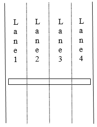
It is typically important to set the detection region in video-based traffic parameter detection in order to decrease the amount of calculation. The detection line method is the most typical technique. The detection line should be established in the traffic image as a straight line with a height of one pixel, the same width as the lane, and perpendicular to the direction of the road. Real-time scan is performed on the pixels on the detection line. Continuous moving pixels indicate that a vehicle is currently past the detection line. The vehicle has passed the detection line when the pixel at the appropriate place turns into a non-moving pixel. As indicated in Figure 1, a detection line can be set up for each lane or a universal detection line can be employed for all lanes. Strong real-time performance, minimal calculation, and the ability to lessen repeated and missed vehicle detection due to lane changes when all lanes share one detection line are all benefits of the detection line vehicle statistics. The fact that the anti-noise ability is so lacking is a drawback. The camera may only be put in the middle of the road because otherwise it is easy to miss detection owing to vehicle occlusion [12]. When there are holes or faults in the detection target, one car is sometimes wrongly identified as two.
In actual engineering, the virtual coil-based detection method is most frequently employed. Its fundamental tenet is to continuously scan the pixels of the virtual coil and determine whether a moving target is present, before identifying the state of the coil in the image. Whether there are vehicles entering and exiting the present image is determined by state changes.
$s=\left\{\begin{array}{l}0, N v=0 \\ 1, N v>0\end{array}\right.$ (1)
where, Nv is the number of pixels of the moving target in the virtual coil; S is the state of the virtual coil (If S=0, no vehicle exists; If S=1, a vehicle exists in the coil).
Three processes make up the virtual coil-based video detection process. The first stage is to gather video, which requires crystal-clear images and is delivered by cameras placed at traffic checkpoints. The second phase is image preprocessing, which is used to make sure that there are no differences between images and that the samples' gray scale, size, and clarity are as uniform as possible. This makes it easier for the next algorithm to process and produces the best detection effect. The third phase entails extracting target data, setting the detection area, or the region of interest to determine whether a vehicle is passing through, and extracting data like vehicle speed [13].
Figure 1. Principle of detection band
By installing twin virtual coils on the captured traffic video frames and running a number of algorithms, the parameters of intelligent traffic information are obtained in this article. Two virtual coils are placed in the detected lane, as illustrated in Figure 2. The red arrow indicates the first coil, while the other is the last coil. The conditions for obtaining characteristics such as vehicle speed, vehicle type, vehicle driving direction, and traffic flow are often satisfied following the setup of the vehicle target.
The basic principle is as follows: Two virtual coils are placed on the necessary lanes to record real-time video of the road surface using a CCD camera. The first virtual coil may detect whether a car is passing by if the frame difference exceeds a certain threshold, however at this time there are not any vehicles nearby. A certain amount of noise pollution might lead to false detection due to shadow, light, and other elements. It is possible to more precisely detect the vehicle's arrival by using the first and last coils. The second coil can work in tandem with the first coil to detect the vehicle speed at the same time. The detection system will recognize that a vehicle is passing by when the gray scale value of the pixel depth in the vertical or parallel traffic flow direction in the monitoring area differs from the gray scale value when there is no car passing. At the same time, the detection system will determine the vehicle's passing speed. To determine the type of vehicle and gauge its speed, factors like the beginning and ending times of the monitoring area are taken into consideration. The necessary traffic parameters are obtained through digital processing and software calculation [14].
The virtual coil-based video traffic parameter detection algorithm is divided into three steps [15].
(1) Clear video frames are necessary for the acquisition of video streams, which are often given by cameras mounted at traffic checkpoints;
(2) Preprocessing the acquired video frames aims to primarily remove image frame differences, ensuring that the samples’size, definition, and grayscale are as uniform as possible, making it easier to process subsequent algorithms and achieving the best detection effect;
(3) Virtual coils are set up to detect whether a vehicle is going by and extract information such as vehicle speed and body color. The detection of target information is the crucial stage in this process.
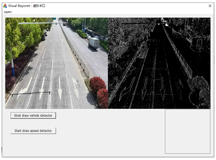
Figure 2. Virtual coil video and its binarization map
3.1 Vehicle detection
The basic process of vehicle target detection module design in this paper is as follows:
Step1: Preprocess the acquired video sequence (including video format conversion, smoothing filtering, etc.);
Step2: Draw the first and last two coils in the video image;
Step3: Initialize the gray value of the virtual coil, that is, the value of the coil pixel when there is no vehicle, and select an appropriate threshold;
Step4: If the difference between frames exceeds the threshold, it is established that the vehicle arrives at the coil, and the image is captured for subsequent processing.
The method of background difference is used to extract the threshold (Figure 3), and it involves first separating the video sequence image from the pattern frame, after which the result is passed through the threshold value to be distinguished. The moving target may be extracted since the pixel that differs from the backdrop model is greater. This technique for contrasting the background with the target can reveal the target's position, size, shape, and other details, allowing for the comprehensive capture of the moving target's information.
The background difference method is useful for getting information on the location, area size, and shape of the moving object directly. The threshold value can be attained more easily. The proper threshold value can be determined by doing statistical experiment calculations after obtaining the difference between the frame pixel value of the frame without the coil and the frame pixel value of the vehicle in the coil numerous times. However, it is highly susceptible to the effects of environmental changes, and it is simple to produce inaccurate information [16].
Figure 3. Workflow of background difference method
An intelligent traffic parameter identification method based on virtual coils is the subject of the algorithm design approach in this study. The method processes video pictures and achieves automatic detection of traffic parameters using the VC++ platform and OpenCV developer kit. The two most crucial elements-vehicle detection and additional vehicle speed detection-are among the parameters used in this study.
3.2 Recognition of body color
Based on the RGB numerical value, the body color is assessed. The light color, which stands for red, green, and blue, is called RGB. Each color's data runs from 0 to 255. If it is 0, it is dark and there is no light. The light is greater as the data set size increases [17]. For 255, the color is white. Finding the color with the greatest data-which can be interpreted as the color's light intensity-will determine which color the vehicle body will be if the data for the three colors are different. Similar red-green values are yellow, similar green-blue values are cyan, and similar red-blue values are magenta if there are two maxima with similar hues. It is gray if the three colors are similar to one another. The light becomes darker and deeper the smaller the dataset is. The light is brighter, or more white and lighter, as the size of the data increases. The computer can determine the color of the body because we have classified body colors in the database [18].
To remove the exposure and reduce the misdetection of silver as white in the algorithm, the authors linearly adjusted the three channels of RGB on the detected vehicle image. The formulas are as follows.
$V_i=C_i \times \alpha-\beta, i=r, g, b, 0<\alpha<1$ (2)
where, C is the RGB of the collected image, with the components depending on i; α=0.6; β=20.
3.3 Vehicle speed detection
For the input traffic video sequence, draw two virtual coils. The first virtual coil judges the existence of the vehicle, and the second virtual coil judges the speed of the vehicle. When calculating the speed of the vehicle, it is first necessary to ascertain that the cars passing through the two virtual coils are the same car [19]. At this time, the two virtual coils are set as A and B, and the time interval of the same vehicle passing through A and B is measured. Then, the mean speed of the car passing through the two virtual coils is solved based on that actual distance. Let x be the distance between the two virtual coils; t1 and t2 be the time for the car passing through the two coils, respectively. Then, the vehicle speed can be calculated by:
$V=x /\left|t_1-t_2\right|$ (3)
Actual on-site video is used to create the experimental video. The virtual coil position of the lane to be detected must first be defined in order for the video to be collected. Daytime and nighttime scenes are used in the experiment, and the experimental data from each scene is analyzed. OpenCV developer kit with VS2010 serves as the test platform.
Figure 4. Initial video frame
As seen in Figure 4, the interface design is separated into five sections: the collected video source player is in the top left, the binarization of the matching video frame is in the upper right, the button to draw two coils is in the lower left, and the detection is in the lower right. The lower middle of the received vehicle's screenshot is where the speed and body color of the identified vehicle can be seen. The detection coils are placed on the lanes that need to be detected in Figure 5. The distance between the two coils needs to be actually measured. It is converted into the number of pixels of the straight-line distance in the video frame. Here, the speed of the vehicle is converted according to the time difference between the first coil and the second coil. The unit is the number of pixels/s.
Figure 5. Lane detection coil
4.1 Daytime video detection
Figure 6 displays the daytime detected vehicle information. It is seen that the first and last coils are placed on the lane to be detected, allowing for vehicle detection on any lane. When the vehicle's front enters the final coil and the change in the trigger coil's pixel value exceeds a certain threshold, the detection occurs. Then, our algorithm takes a screenshot of the region where the vehicle is present, computes its speed, and displays that data together with other details. As seen in Figures 6(i) and 6(j), where the second lane is detected and the third lane is detected by others, the lane selection can also be arbitrary.
Figure 6. Detection effect of daytime video
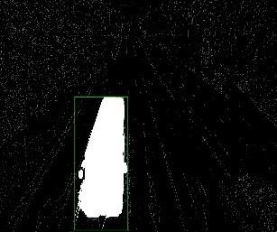
Figure 7. Vehicle passing the first coil
Figure 8. Screenshot of vehicle region by background difference method
Figure 9. Vehicle passing the last coil
Figure 10. Screenshot of vehicle region by background difference method
Table 1. Detection of vehicle speeds in daytime
|
Vehicle information |
Distance between first and last coils |
Detected speed |
Corresponding speed |
Actual speed |
|
Figure 6 (a) |
4.2m |
408.46pixes/s |
7.1km/h |
8 km/h |
|
Figure 6 (b) |
4.2m |
5310.00pixes/s |
91.2km/h |
88 km/h |
|
Figure 6 (c) |
4.2m |
441.97pixes/s |
7.68 km/h |
8.5 km/h |
|
Figure 6 (d) |
4.8m |
3210.00pixes/s |
60.36 km/h |
62 km/h |
|
Figure 6 (e) |
4.3m |
5580pixes/s |
96.99 km/h |
95 km/h |
|
Figure 6 (f) |
4.7m |
94.55pixes/s |
1.64 km/h |
3 km/h |
|
Figure 6 (i) |
3.3m |
762pixes/s |
13.26 km/h |
14.5 km/h |
|
Figure 6 (g) |
3.4m |
231.17pixes/s |
4.02 km/h |
5 km/h |
|
Figure 6 (h) |
3.4m |
316.15pixes/s |
5.5 km/h |
6 km/h |
Figure 6 illustrates how the influence of shadows poses the biggest challenge to the vehicle detection effect on sunny days. The shadow area of the detected huge car is very large, as seen in Figure 6(f). Thus, when detecting the color, the vehicle body color is used. It was wrongly identified as being black. This is because there is an issue with the body's reaction. The color of the car's region in the screenshot is accurate. Since the video frame is unaffected by shadows in the cloudy sky, as seen in Figures 6(i) and 6(j), huge vehicles are detected well, and the color inspection is also fairly accurate. Here, the image of the car in Figure 6(j) going through the first and last coils is chosen. The absolute difference between the accumulated sum of pixels in the virtual coil and the accumulated sum of pixels at the position of the corresponding mode frame exceeds a predetermined threshold, as shown in Figure7, when the vehicle passes through the first coil, activating the mechanism of intercepting the vehicle and intercepting the position of the target vehicle. The target vehicle's area as collected using the background difference method is shown in Figure 8. The corresponding screenshot of the vehicle region is displayed in Figure 9. Figure 10 shows the target vehicle intercepted by the corresponding background difference method.
Vehicle detection is done at junctions, where traffic is typically moving more quickly when the light is green and less quickly when it is red. Table 1 lists the passing times of the first and last coils for the nine cars in Figure 6 together with the matching vehicle speeds. The unit of vehicle speed is pixels/s, and the actual distance between the first and last coils is measured on-site. Table 1 shows that the vehicle speed detection effect is comparatively accurate, the difference between the actual measured vehicle speed and the detected vehicle speed is essentially small, and the reliability is good.
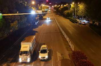
4.2 Nighttime video detection
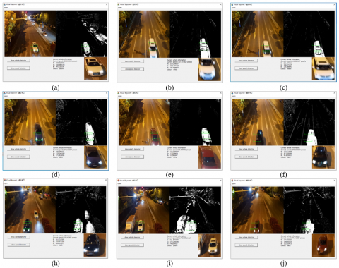
Additionally included are 9 cars for the nighttime environment. The lighting setting is highly complex, as the road is at a junction, where s Street lights, front and back lights of vehicles, and building lights are all present and alternatively blended. Light has a significant impact on vehicle detection, and the distortion of vehicle body color detection is more pronounced. The body is clearly white, as seen in Figures 11(a) and (c), and as a result of the influence of light, the detecting area's color likewise varies. The test result is yellow because it is clear that the color of the road surface has changed from gray to yellow generally. Additionally, shadows are more likely to appear at night. The body of the red car is impacted by a number of variables in the detection area, as seen in Figure 11(g), and the color detection result is displayed as black. If the vehicle is moving too quickly while being detected, motion blur will also be visible in the screenshot of the vehicle image, as shown in Figures 11(b), 11(c), and 11(f).
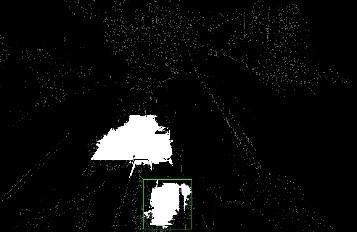
When the vehicle passes through the first coil in the screenshot of the vehicle passing through the first and last coils (Figure 11(i)), as shown in Figure 12, the absolute difference between the accumulated sum of pixels in the virtual coil and the accumulated sum of pixels in the corresponding mode frame position exceeds the predetermined threshold, triggering the mechanism of intercepting the vehicle and intercepting the position of the target vehicle. The target vehicle's region as acquired by the background difference method is shown in Figure 13. It is evident that there is a small inaccuracy brought on by the light. The front light causes regional pixel variation, which is mistaken as a car passing by.
Figure 11. Detection effect of night video
Figure 12. Vehicle passing the first coil
Figure 13. Screenshot of vehicle region by background difference method
Figure 14. Vehicle passing the last coil
Figure 15. Screenshot of vehicle region by background difference method
Figure 14 is the screenshot of vehicle passing the last coil, and Figure 15 is the vehicle region by background difference method. It can be seen that the background difference method can detect the passing cars excellently. Table 2 lists the passing times of the first and last coils for the nine cars in Figure 11 together with the matching vehicle speeds. The unit of vehicle speed is pixels/s, and the actual distance between the first and last coils is measured on-site.
It can be seen from Table 2 that at night, the error between the detected vehicle speed and the actual vehicle speed is small, exhibiting a high detection reliability.
In the daytime experiment, the total number of vehicles passing by the detected lane is 75 when the weather is sunny, the total number of vehicles passing by the detected lane is 68 when the weather is cloudy, and the total number of vehicles passing by the detected lane at night is 72. The specific detection data are shown in Table 3.
It can be seen from Table 3 that the accuracy of vehicle detection is very high in the daytime, and the accuracy can reach more than 90% in the night. On the whole, in complex environments, the reliability of vehicle detection based on dual coils is relatively high. For the detection of body color, the accuracy is also high during the day, but the detection accuracy of the body color is low at night, due to the influence of light. This is particularly the case when the car body is white, which is often falsely detected as yellow.
Several machine vision-based vehicle detection algorithms were tested under the same junction environment. Table 4 compares the performance of our algorithm with vehicle detection algorithms like optical flow method, frame difference method, background difference method, and virtual coil method. The geomagnetic induction coil method needs to bury the geomagnetic induction coil under the road and generate a current signal when the vehicle passes through to detect the vehicle. This physical method boasts a high accuracy, but the cost is high and the construction is complicated.
Table 5 compares the performance of our algorithm with that of several other algorithms. Overall, the proposed dual coil-based transportation parameter detection method has a certain advantage. The optical flow method, frame difference method, background difference method, and virtual coil method fail to achieve a good real-time performance in vehicle speed and body color detections. The proposed method performs well instantaneously, despite the effect of external factors. It can detect vehicles, and extract many parameters, such as speed, body color, and driving direction.
Table 2. Detection of vehicle speeds in nighttime
|
Vehicle information |
Distance between first and last coils |
Detected speed |
Corresponding speed |
Actual speed |
|
Figure 11 (a) |
3.1m |
420.00pixes/s |
7.31km/h |
8.2km/h |
|
Figure 11 (b) |
4.6m |
1117.87pixes/s |
19.46km/h |
21.4km/h |
|
Figure 11 (c) |
4.9m |
1140.38pixes/s |
19.85km/h |
21.5km/h |
|
Figure 11 (d) |
4.3m |
304.10pixes/s |
5.29km/h |
6km/h |
|
Figure 11 (e) |
4.4m |
430.91pixes/s |
7.50 km/h |
8km/h |
|
Figure 11 (f) |
4.5m |
2370pixes/s |
41.25 km/h |
42.3km/h |
|
Figure 11 (i) |
3.3m |
207.14pixes/s |
3.61 km/h |
4.3km/h |
|
Figure 11 (g) |
3.3m |
201.70pixes/s |
3.55 km/h |
4.2km/h |
|
Figure 11 (h) |
3.3m |
677.14pixes/s |
11.79 km/h |
12.5km/h |
Table 3. Vehicle detection conditions during the day
|
Environment |
Actual number of vehicles |
Detected number |
Accuracy |
Number of correct color detections |
Accuracy of color detection |
|
Sunny scene |
75 |
71 |
94.67% |
60 |
80% |
|
Cloudy scene Night scene |
68 72 |
67 65 |
98.53% 90.28% |
65 41 |
95.59% 56.94% |
Table 4. Performance of vehicle detection algorithms
|
Parameter Algorithm, environment |
Vehicle detection accuracy |
|
|
Optical flow method [4] |
Sunny scene |
86.23% |
|
Cloudy scene Night scene |
95.61% |
|
|
Sunny scene |
80.25% |
|
|
Frame difference method [5] |
Sunny scene |
81.25% |
|
Cloudy scene Night scene |
85.66% |
|
|
Sunny scene |
78.35% |
|
|
Background difference method [6] |
Sunny scene |
84.32% |
|
Cloudy scene Night scene |
92.51% |
|
|
Sunny scene |
82.15% |
|
|
Virtual coil method [3] |
Sunny scene |
92.15% |
|
Cloudy scene Night scene |
96.62% |
|
|
Sunny scene |
86.20% |
|
|
Our algorithm |
Sunny scene |
94.67% |
|
Cloudy scene Night scene |
98.53% |
|
|
Sunny scene |
90.28% |
|
Table 5. Transportation parameter detection
|
Method |
Hardware cost |
Real-time performance |
Environmental requirement |
Accuracy |
Robustness |
|
Geomagnetic induction coil method [3] |
The equipment is expensive and the road surface needs to be broken |
Strong |
Not affected |
High |
Good |
|
Optical flow method [4] |
High requirements for cameras and expensive equipment |
Weak |
Easily affected by factors such as light |
High |
Poor |
|
Frame difference method [5] |
Simple algorithm |
Strong |
Vulnerable to vehicle speed |
Low |
Good |
|
Background difference method [6] |
Huge computing load |
Weak |
vulnerable to external factors |
Low |
Good |
|
Virtual coil method [3] |
Simple algorithm and small computing load |
Strong |
Easily affected by complex environments |
Low |
Good |
|
Our algorithm |
Simple algorithm and small computing load; able to detect multiple parameters |
Strong |
Easily affected by complex environments |
High |
Good |
In this study, a traffic parameter recognition method based on double virtual coils is developed, and the camera at the actual junction used in the experiment collects the traffic video data stream needed for the experiment. The road does not need to be repaired for the experiment, the overall engineering volume is tiny, and installing the camera is easy. Then, the proposed algorithm is adopted to emulated geomagnetic induction coils. Vehicles in the target area can be detected by combining the frame difference and background difference algorithms in the region. Double virtual coils are established as the detection area on the captured video frame to reduce the amount of calculation. The frame difference time of the vehicle target passing through the first and last two coils is used to determine the vehicle speed information. The body color of the vehicle identified in the target region can also be determined using the time difference between the first and final two coils, which has no impact on the algorithm as a whole. The experiment is simpler to construct and less expensive than the conventional geomagnetic induction coil detection algorithm, for it does not require tearing up the road's surface. There is no need to rebuild if the lane is added. The methodology presented in this research is faster and more real-time than the optical flow method, which requires the addition of a dynamic camera. Its detection accuracy is higher than that of the background difference approach and the inter-frame difference method. The impact of light and shadow on traffic video in a sunny setting and at night detection will be researched in the follow-up work [20], aiming to further increase the precision of traffic parameter detection.
This work was supported by the Anhui Province University Outstanding Young Talents Support Plan (Grant No.: gxyq2017050); Universities Joint Key Laboratory of photoelectric detection Science and Technology in Anhui Province (Grant No.: 2020GDTC01); Anhui Province University Collaborative Innovation Project (Grant No.: GXXT-2021-091, GXXT-2022-045); Horizontal project of Hefei Normal University (Grant No.: HXXM2022238).
[1] Lu, X., Song, Z., Zhu, X. (2012). Urban traffic congestion detection based on clustering analysis of real-time traffic data. Journal of Geo-Information Science, 14(6): 775.
[2] Li, S. (2012). A survey of urban traffic coordination controls in intelligent transportation systems. In Proceedings of 2012 IEEE International Conference on Service Operations and Logistics, and Informatics, pp. 177-182. https://doi.org/10.1109/SOLI.2012.6273526
[3] Xie, E., Shen, Y.Z., Wang, P. (2005). A video detection algorithm that simulates the working mode of the inductive coil. Computer and Digital Engineering, 33(4): 31-33.
[4] Kwan, C., Budavari, B. (2020). Enhancing small moving target detection performance in low-quality and long-range infrared videos using optical flow techniques. Remote Sensing, 12(24): 4024-4025. https://doi.org/10.3390/rs12244024
[5] Shi, G., Suo, J., Liu, C., Wan, K., Lv, X. (2017). Moving target detection algorithm in image sequences based on edge detection and frame difference. In 2017 IEEE 3rd Information Technology and Mechatronics Engineering Conference (ITOEC), pp. 740-744. https://doi.org/10.1109/ITOEC.2017.8122449
[6] He, L., Ge, L. (2018). CamShift target tracking based on the combination of inter-frame difference and background difference. In 2018 37th Chinese Control Conference (CCC), pp. 9461-9465. https://doi.org/10.23919/ChiCC.2018.8483706
[7] Chandra Shit, R. (2020). Crowd intelligence for sustainable futuristic intelligent transportation system: a review. Iet Intelligent Transport Systems, 14(6): 480-494. https://doi.org/10.1049/iet-its.2019.0321
[8] Wang, X.J., Zhang, J.S., Song, X.H. (2019). International research and development hotspots of intelligent transportation system. Science & Technology Review, 37(6): 36-43.
[9] Cao, J., Song, C., Song, S., Peng, S., Wang, D., Shao, Y., Xiao, F. (2020). Front vehicle detection algorithm for smart car based on improved SSD model. Sensors, 20(16): 4646. https://doi.org/10.3390/s20164646
[10] Abdullah, M.N., Ali, Y.H. (2021). Vehicles detection system at different weather conditions. Iraqi Journal of Science, 2040-2052. https://doi.org/10.24996/ijs.2021.62.6.30
[11] Wang, C., Huang, L., Li, Z. (2020). Research on multi vehicle tracking based on TLD optimization algorithm. In Journal of Physics: Conference Series, 1682(1): 012057. https://doi.org/10.1088/1742-6596/1682/1/012057
[12] Lv, Y.S., Chen, Y.Y., Jin, J.C., Li, Z.J., Ye, P.J., Zhu, F.H. (2019). Parallel transportation: Virtual-real interaction for intelligent traffic management and control. Chinese Journal of Intelligent Science and Technology, 1(1): 21-23. https://doi.org/10.11959/j.issn.2096-6652.201908
[13] Liu, H.X., Sun, J. (2014). Length-based vehicle classification using event-based loop detector data. Transportation Research Part C: Emerging Technologies, 38: 156-166. https://doi.org/10.1016/j.trc.2013.11.010
[14] Xiang, X., Zhai, M., Lv, N., El Saddik, A. (2018). Vehicle counting based on vehicle detection and tracking from aerial videos. Sensors, 18(8): 2560. https://doi.org/10.3390/s18082560
[15] Cui, Z., Zhang, Q.M. (2011). A traffic information flow analysis method based on virtual coils. Journal of Bijie University, 29(4): 68-75. https://doi.org/10.3969/j.issn.1673-7059.2011.04.013
[16] Le, Y., Zhao, Z.C. (2020). Multi-movement object detection and partition based on the background difference method. Chinese Journal of Engineering Machinery, 4: 305-309.
[17] Russell, A., Zou, J.J. (2012). Vehicle detection based on color analysis. In 2012 International Symposium on Communications and Information Technologies (ISCIT), pp. 620-625. https://doi.org/10.1109/ISCIT.2012.6380975
[18] Chien, S.C., Chang, F.C., Tsai, C.C., Chen, Y.Y. (2017). Intelligent all-day vehicle detection based on decision-level fusion using color and thermal sensors. In 2017 International Conference on Advanced Robotics and Intelligent Systems (ARIS), pp. 76-76. https://doi.org/10.1109/ARIS.2017.8297189
[19] Sangnoree, A., Chamnongthai, K. (2009). Robust method for analyzing the various speeds of multitudinous vehicles in nighttime traffic based on thermal images. In 2009 Fourth International Conference on Computer Sciences and Convergence Information Technology, pp. 467-472. https://doi.org/10.1109/ICCIT.2009.186
[20] Lin, C.T., Huang, S.W., Wu, Y.Y., Lai, S.H. (2020). GAN-based day-to-night image style transfer for nighttime vehicle detection. IEEE Transactions on Intelligent Transportation Systems, 22(2): 951-963. https://doi.org/10.1109/TITS.2019.2961679