Jianhua Zhang* | Qiang Zhu | Fei Song | Lingchao Zhang | Juan Wang | Changjun Liu
© 2022 IIETA. This article is published by IIETA and is licensed under the CC BY 4.0 license (http://creativecommons.org/licenses/by/4.0/).
OPEN ACCESS
This paper conducts a research on the wavelet construction and application of image edge detection. Taking the image edge detection algorithm based on wavelet modulus maxima as the research subject, this paper discusses the problem of dislocation phenomenon, threshold selection, multi-scale edge fusion and evaluation criterion in the algorithm, and proposes an improved self-adaptive hierarchical threshold algorithm based on information amount and vanishing moment. From the angle of wavelet symmetry, filter composition and vanishing moment, the influence of wavelet property on image edge detection is studied, and the construction requirements of wavelet filter banks for image edge detection are proposed. The constant-length compactly supported biorthogonal wavelet parameterized construction method is used to construct the biorthogonal wavelet featuring odd symmetry for high-pass decomposition filter and unidirectionality for filter sequence, and the improved algorithm of wavelet construction and threshold is applied to the simulation of image edge detection of concrete cracks in ultra-high arch dam.
wavelet construction, image edge detection based on wavelet modulus maxima, biorthogonal wavelet, constant-length compactly supported biorthogonal wavelet, ultra-high arch dam, concrete crack
As the most basic feature of an image, edge is expressed as a set of pixels with step change or roof change in the gray level of the surrounding pixels in the image, indicating the end of one region and the beginning of the position of another region [1-3]. Gray discontinuity may be caused by physical or geometric factors, such as discontinuity of depth, surface orientation, and discrepancy of color and texture [4, 5]. It may also arise from optical factors, such as surface reflection, shadows generated by non-target objects, and internal reflections. The edge exists between the target and the background, the target and the target, and the region and the region. It can outline the geometric contour characteristics of the object and transmit a variety of information of the image. It is an important feature to describe the object image, and provides valuable and important feature parameters for people to describe or recognize the target and interpret the image.
Edge detection [6-8] is a basic subject of image processing and analysis, which is of great significance. Edge is very useful for human visual recognition. People often recognize targets according to boundary contour and edge features, and the expression of edge is easy to be introduced into various target recognition algorithms. The success of many target recognition ultimately depends on the quality of edge detection. Therefore, the research on the means of signal and image edge detection has important practical value.
Edge detection is a basic subject of image processing and analysis, which is of great significance. Edge is very useful for human visual recognition [9, 10]. People often recognize targets according to boundary contour and edge features [11], and the expression of edge is easy to be introduced into various target recognition algorithms [12]. The success of many target recognition ultimately depends on the quality of edge detection. Therefore, the research on the means of signal and image edge detection has important practical value.
The traditional edge detection method is based on spatial operation [13-15], which is realized by convolution with the help of spatial differential operators, and plays the role of high pass filtering. These operators use the changes of the first-order or second-order directional derivatives of adjacent edges to perform edge direction, which is bound to be extremely sensitive to noise, and the ability to remove noise is poor, and noise will be introduced in the edge extracting.
2.1 Development of multi-scale edge detection
The concept of multi-scale edge detection [16] was first proposed by Rosenfeld, and then gradually improved by Marr, Hildreth, and Witkin et al., forming the basic theory of multi-scale edge detection. The idea of multi-scale edge detection is to conduct smooth filtering in a certain range of the image, and then use a group of filters to detect the edges in different ranges. Gaussian filter is usually selected as the smoothing filter, which features spatial stability and small spatial position error, and the non-directional Laplace operator is chosen as the edge detection operator, which is the Marr-Hildreth edge detection algorithm, in which the parameter δ is the space constant of Gaussian function. By changing δ, edge graphs of different scales can be obtained. However, Marr-Hildreth edge detection algorithm does not provide the specific method of how to combine the edge images output by different scale filters into a single and correct edge image, so it is difficult to be used in practice.
For this reason, Witkin proposed the scale space theory. Scale space refers to (δ, x), where δ and x are scale parameters and position parameters respectively. The signal is described by the curve of relationship between its zero-crossing curve and scale parameters in the scale space. This multi-scale edge detection method first detects the zero-crossing points of larger scales, and then searches downward for the position at the smaller scale δ through the zero crossing curves where the points are on to determine the position of the edge.
The disadvantage of this method is that it cannot be realized automatically by computer [17], and there is no unified standard for how to select a larger scale to reflect the zero crossing of the real edge of the image, which is still difficult to realize in practical use.
The multi-resolution characteristic of wavelet analysis provides a new method for multi-scale edge detection [18]. The multi-resolution analysis of signals using wavelet transform is very suitable for extracting local features of signals. Wavelet transform is a bivariate time-frequency analysis method. Its scale factor and shift factor constitute a time-frequency window that can be expanded and translated. The transformation coefficient in small scale corresponds to the high-frequency component of the signal, while the transformation coefficient in large scale corresponds to the low-frequency component of the signal [19]. Through multi-scale decomposition, the signal can be decomposed into components at each frequency, so that the local characteristics of the signal corresponding to different frequencies can be detected. For the image, the edge part and noise belong to high-frequency information. Wavelet transform can not only extract the image edge, but also effectively suppress the noise. Therefore, wavelet analysis is a multi-scale edge detection method with excellent de-noising ability and complete edge detection ability [20].
2.2 Representation of edges in wavelet transform
At scale s, the wavelet transform of function f (x) at point x is:
$W f(s, x)=f * \psi_{s}(x)$
If θ(x) is a smoothing function, and its integral is non-zero. Generally, the energy of the smoothing function is usually concentrated in the low frequency band, so the smoothing function can be regarded as the system response function of the low-pass filter. Thus, the convolution (f*θ) (x) of function f(x) and θ(x) attenuates the high-frequency signal of f(x) without changing the low-frequency part, which is equivalent to smoothing the function f(x). If ψ(x) is a wavelet function, taking $\psi^{1}(x)=\frac{d \theta(x)}{d x} \quad \psi^{2}(x)=\frac{d^{2} \theta(x)}{d x^{2}}$, and the wavelet transform of function f(x) is defined as:
$W^{1} f(s, t)=\left(f * \psi_{s}^{1}\right)(x) W^{2} f(s, t)=\left(f * \psi_{s}^{2}\right)(x)$,
then:
$W^{1} f(s, t)=\left(f * s \frac{d \theta_{s}}{d x}\right)(x)=s \frac{d}{d x}\left(f * \theta_{s}\right)(x)$
$W^{2} f(s, t)=\left(f * s^{2} \frac{d^{2} \theta_{s}}{d x^{2}}\right)(x)=s^{2} \frac{d^{2}}{d x^{2}}\left(f * \theta_{s}\right)(x)$
The wavelet transform coefficients $W^{1} f(s, t)$ and $W^{2} f(s, t)$ of function f(x) are in direct proportion to the first and second derivatives of f(x) after it is smoothed by θs(x). The extreme point of the first derivative of the function corresponds to the zero point of the second derivative, that is, the inflection point of the function f(x), and the maximum point of the absolute value of the first derivative corresponds to the mutation point of the function.
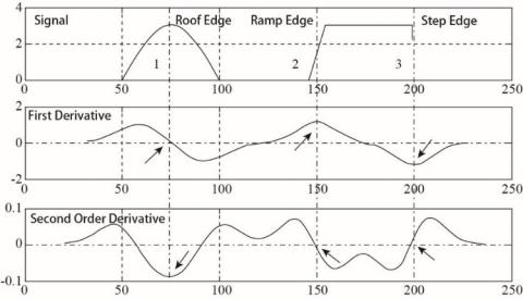
Figure 1 shows several common edge models, where 1 is the ridge edge, 2 is the slope edge, and 3 is the step edge. From the waveforms of the first and second derivatives of the signal after it is smoothed by Gaussian function, it can be seen that for the ridge edge, the first derivative is reflected as the zero crossing point, and the second derivative is the maximum point; for the step edge, the first derivative is the maximum point, while the second derivative is the zero crossing point; the status of slope edge is the same as that of step edge, therefore, the slope edge can be regarded as a special case of step edge.
According to the above analysis, if the wavelet function is the first derivative of the smoothing function, the maximum point of the absolute value of the wavelet transform coefficient Wf(s, t) corresponds to the mutation point in the signal. In image edge detection, the modulus maxima point of wavelet transform also corresponds to the edge points of the image. Due to the multi-scale analysis characteristics of wavelet transform, the edge information of image on multi-scale can be obtained through wavelet transform, so it is called multi-scale edge detection.
Figure 1. Shape of edge type in wavelet transform
2.3 Edge detection algorithm based on wavelet modulus maxima
From the definition of modulus maxima point, it can be seen that the mutation point of signal will produce corresponding modulus maxima points on different scales. The variation of the amplitude of the modulus maximum with the scale parameter depends on the Lipschitz exponent of the signal at that point.
f(x, y) is taken as an image, and its gradient vector ∇f represents the maximum change direction of the image at point (x, y). Let (x1, y1) be a pixel of the image. If the modulus of the gradient vector varies in the one-dimensional neighborhood of the point (x1, y1) along the direction of maximum change, and the local modulus maximum is obtained at this point when |λ| is sufficiently small, then point (x1, y1) is regarded as an edge point of image f(x, y).
$|\nabla f|=\sqrt{\left|\frac{\partial f}{\partial x}\right|^{2}+\left|\frac{\partial f}{\partial y}\right|^{2}}$ (1)
$(x, y)=\left(x_{1}, y_{1}\right)+\lambda \nabla f\left(x_{1}, y_{1}\right)$ (2)
The multi-scale edge detection algorithm based on wavelet transform modulus maxima mainly consists of the following steps:
1. Under the scale s=2j, the two-dimensional wavelet transform coefficients $W^{1} f(j, m, n)$ and $W^{2} f(j, m, n)$ of each point in the image in two directions are calculated, and the decomposition scale is generally between 3 and 5. The wavelet transform coefficients in two directions are equivalent to the horizontal detail coefficients and vertical detail coefficients when using wavelet transform for image decomposition. The calculation process of the transform coefficients is carried out by adopting two-dimensional convolution algorithm, so as to obtain a faster calculation speed;
2. The gradient amplitude and phase angle of each point are calculated according to formula (1) and formula (2). Gx and Gy are used to judge the extension direction of the gradient at the current point and the gradient phase angle between [0, 2π] is provided;
3. Traverse each point, compare the amplitudes of the adjacent front and rear points according to the gradient extension direction based on the obtained gradient phase angle, and take the point with the largest modulus as the candidate edge point;
4. Block threshold method is applied to remove the edge points with smaller modulus maxima among the candidate edge points;
5. For single scale wavelet transform edge detection, the modulus maxima constitute the edge map; for multi-scale edge detection, the modulus maxima points of each scale should be merged.
Figure 2 is the flow chart of edge detection algorithm based on modulus maxima of wavelet transform.
Figure 2. Flow chart of edge detection algorithm based on modulus maxima of wavelet transform
Figure 3. Judgment of gradient extension direction in maximum modulus detection
In the judgment of modulus maxima points, since there are 8 adjacent points (except the boundary) around any pixel point, they divide a region into 8 sectors, as shown in Figure 3. Assuming that the pixel coordinates of the central position are (i, j), the region is divided into 8 parts along the dotted line in the figure, representing 8 different gradient directions. The judgment of the modulus maximum point is based on the position of the phase angle of the pixel point in the sector. Due to the symmetry of the gradient direction, the same algorithm can be used to judge the modulus maximum point of two opposite sectors. If the phase angle is in sector ①, then compare the value of the current point with those of the left and right pixels.
Due to the multi-scale analysis characteristics of wavelet transform and the noise suppression ability of wavelet transform, wavelet analysis has been widely used in edge detection. There are many kinds of wavelets with different features. The corresponding wavelet transform also has its own scope of application. Not all wavelets are suitable for edge detection. Choosing an appropriate wavelet has an important impact on the result of edge detection [3-5]. From the requirements of edge detection, the selected wavelet should have the ability of fast detection and accurate edge positioning. At the same time, because both the actually processed images and signals contain noise, the necessary anti-noise ability is also a factor to be considered when selecting wavelet.
3.1 Influence of symmetry on edge detection
3.1.1 Symmetry and edge positioning
The wavelet transform of the signal can be realized through the recurrence of the filter bank. h(n) and g(n) are set as low-pass and high-pass filters, $\hat{h}$ and $\hat{g}$ are their corresponding Fourier transform forms, S is the signal to be processed, j is the scale parameter, and W is the detail coefficient of wavelet transform, then:
$S_{j+1}(n)=S_{j}(n) * h_{j}(n)$ (3)
$W_{j+1}(n)=S_{j}(n) * g_{j}(n)$ (4)
The discrete Fourier transform of M at both ends of the above two formulas are chosen respectively to obtain:
$S_{j+1}(u)=S_{j}(u) \hat{h}_{j}(n)$ (5)
$W_{i+1}(u)=S_{i}(u) \hat{g}_{i}(u)$ (6)
If h(n) is an even symmetric filter about the axis of symmetry a, that is $\hat{h}(\omega)=\widehat{h}_{0}(\omega) e^{i a \omega}$ , then:
$\hat{h}_{c}(u)=\hat{h}_{0 c}(u) e^{\frac{i 2 \pi a u c}{M}}$ (7)
The following can be obtained from formula (5):
$S_{j}(u)=S_{1}(u) \prod_{c=1}^{j-1} \hat{h}_{c}(u)$ (8)
The following can be obtained when formula (8) is substituted into formula (6):
$W_{j}(u)=S_{1}(u) g_{j-1}(u) \prod_{c=1}^{j-1} \hat{h}_{c}(u)$ (9)
The following can be obtained when formula (7) is substituted into formula (8):
$S_{j}(u)=S_{1}(u)\left(\prod_{c=1}^{j-1} \hat{h}_{0 c}(u)\right) e^{\frac{i \pi u}{M} a j(j-1)}$ (10)
If the high-pass filter $g(n)$ has odd symmetry, then
$\hat{g}(\omega)=i \operatorname{sgn}(\omega) \hat{g}_{0}(\omega) e^{i b \omega}$
The following can be obtained when formula (7) is substituted into formula (9):
$W_{j}(u)=S_{1}(u) \hat{g}_{0, j-1}(u) \prod_{c=1}^{j-1} \hat{h}_{0, c}(u) e^{\frac{i \pi u}{M}(j-1)(a j+2 b)}$ (11)
It can be seen from Eqns. (10) and (11) that when the low-pass filter h is even symmetric about the axis of a and the high-pass filter g is odd symmetric about the axis of b, a shift of (j-1)(aj+2b) will emerge at the edge under scale j, and the displacement will rise with the increase of scale, and the positioning ability of the edge will become worse and worse. However, if both low-pass and high pass filters have zero symmetry, then a=b=0 at this time, and there will be no shift, and the edge positioning accuracy is the highest at this time.
3.1.2 Sequence composition and edge detection of high pass decomposition filter
Wavelet low-pass filter can only be even symmetric, while high pass filter can be either odd symmetric or even symmetric. Although the wavelet with zero as the center of symmetry will not shift when the image is decomposed, it does not mean that the wavelet with zero as the center of symmetry has the best edge detection effect. In addition to accurate positioning, whether it is able to find out the most edge information is a prerequisite for image edge detection, and the displacement problem can be corrected by displacement compensation. In addition, when the high pass filter is odd symmetric, the minimum support can be obtained by taking 1/2 point as the axis of symmetry; when the high pass filter is even symmetric, the minimum support can be obtained by taking the zero point as the axis of symmetry. Considering the amount of computation of wavelet transform, biorthogonal wavelet decomposition meeting the above two conditions is the simplest, which is also the reason why the biorthogonal wavelet currently used are only odd symmetric at 1/2 points and even symmetric at zero points.
In the process of image decomposition, approximate information is obtained through the convolution of low-pass decomposition filter and the image, and detail information is obtained through the convolution of high-pass decomposition filter and the image, while the edge information of the image is retained in the detail coefficients of each scale. Therefore, it is of great significance to study the composition of wavelet high pass decomposition filter for image edge detection. Here, taking a simple circle image as an example, wavelet with different characteristics is used for high pass decomposition. By studying the results of row and column components under high pass decomposition, the composition conditions of wavelet high pass decomposition filter are analyzed. Figure 4 shows the row and column component results obtained from the decomposition of four wavelet circle images, and the decomposition level is 1. The four wavelets selected are shown in Table 1. They have different filter lengths and different filter elements.
Figure 4. Column and row component of the image of Circle decomposed by four wavelets
Table 1. Four wavelets applied in Circle image decomposition
|
Wavelet |
Symmetry |
High pass decomposition filter |
Length of carried set |
Directivity of sign |
|
rbio3.1 |
Odd symmetry1/2 |
[0.35361.0607-1.0607-0.3536] |
4 |
Positive→Negative |
|
bior1.3 |
Odd symmetry 1/2 |
[-0.707110.70711] |
2 |
Negative→Positive |
|
bior3.3 |
Odd symmetry 1/2 |
[-0.176780.53033-0.530330.17678] |
4 |
Interlaced |
|
bior5.5 |
Even symmetry 0 |
[-0.013457,-0.002695, 0.13671,-0.093505,-0.4768,0.89951,……] |
11 |
Interlaced |
Table 2. Row components of decomposition of the right middle boundary of Circle image by four wavelets
|
Wavelet |
Position |
Row component composition |
|
rbio3.1 |
Row 58~66, Column 95 |
[0.35355,1.4142,0.35355] |
|
bior1.3 |
Row 57~65, Column 95 |
[0,-0.70711,0] |
|
bior3.3 |
Row 56-64, Column95 |
[-0.17678,0.35355,-0.17678] |
|
bior5.5 |
Row 54-62, Column 95 |
[-0.013457,-0.016152,0.12055,0.02705,-0.44975, 0.44975,-0.02705,-0.12055,0.016152,0.013457] |
It can be seen from the row and column decomposition component results of the image circle that when the high pass decomposition filter of wavelet is different, there will be many differences in direction, intensity and shape reflected in the row and column component. Their main differences lie in:
(1). Shape and directivity of column components
The row components obtained by the four wavelets in Figure 4 are visually distributed in different positions. The column component of rbio3.1 wavelet shows the right half, bior1.3 wavelet shows the left half, and bior3.3 and bior5.5 wavelets basically show the whole circle. The same situation also exists in the column components. The difference in the composition of the four wavelet high pass decomposition filter sequences is the reason for this phenomenon. Because the high pass filter sequence elements of rbio3.1 wavelet are left positive and right negative, and in the convolution process, the result of the right half is positive and the left half is negative, so only the right half column components can be seen in the display; Similarly, the high pass filter sequence elements of bior1.3 wavelet are left negative and right positive, and only the left half of the column components can be seen when displaying; for bior3.3 and bior5.5 wavelets, because the sequence elements have no directivity, the detection results will show most of the circles. Here, the wavelet filter sequence elements are called unidirectional filters for their characteristics of from positive to negative or from negative to positive.
(2). Strength of row and column components
In addition to the different directionality of row and column components, the strength of row and column components in the detection results is also found different. In the high pass decomposition filter sequence, the greater the difference between positive and negative elements, the more obvious the edge detection result is, that is, the greater the intensity is. In Figure 4, the edge of the row and column components of rbio3.1 wavelet is more obvious than those of other wavelets.
(3). Composition of edge pixels
In the circle image, the contour in the middle of the right side is selected as the inspection range of edge pixels, and its circular boundary is within row 60~68 and column 95. Due to the different high pass decomposition filters, there are also great differences in the column components of the boundary decomposed by the four wavelets. See Table 2 for the decomposition result.
The high pass decomposition filter of rbio3.1 wavelet and bior1.3 wavelet changes in one direction, which is very similar to the differential operator in traditional edge detection, and is very sensitive to the change position of gray in the image. However, the other two wavelets do not have this feature, so there is no obvious difference between the central pixel of their row component edge and the adjacent pixel points. Therefore, in image edge detection, the sequence elements of wavelet high pass decomposition filter should be unidirectional, that is, it must have odd symmetry (See Figure 5).
Figure 5. Corresponding relationship between row components and high-pass decomposition filter (dh)
In edge detection, if the edge can be represented by fewer pixels, it can not only reflect the image edge position information more clearly, but also improve the detection efficiency. Comparing the wavelet high pass decomposition filter in Table 1 with the row component decomposition results in Table 2, due to the function of convolution, the longer the filter support is, the longer the length of the decomposed row and column components is, which will weaken the image edge and greatly increase the computational complexity. Therefore, the support length of wavelet high pass decomposition filter should not be too long.
(4). Occurrence of dislocation
In the process of multi-scale edge detection, when the image is decomposed by wavelet, there will be dislocation, that is, the position of pixels in the decomposition detail coefficient will shift relatively to the previous layer. There are two reasons for the position change:
$\tilde{h}_{k}=\tilde{h}_{2 \alpha-k} \quad \tilde{g}_{k}=\tilde{g}_{2 \alpha-k}$
Figure 6. Comparison of effect of concrete crack edge detection by wavelets with different high pass decomposition filter characteristics
If the wavelet decomposition of the jth layer is currently performed, the shift amount M of the high-frequency component is:
$M=(\alpha+\beta) \cdot 2^{j-1}-\alpha \quad j=0,1,2, \cdots$
From the above formula, it can be concluded that when the wavelet decomposition filter $\tilde{}$ and $\tilde{g}$ are both symmetric about zero, that is α=β=0, the edge of each scale will not shift; when the decomposition filter $\tilde{}$ symmetric about zero, and $\tilde{\mathrm{g}}$ there will be displacement in the edge image obtained at all scales, and displacement compensation is needed to ensure the accurate positioning of the edge.
Through the analysis of the decomposition of the row and column components of wavelet high pass decomposition filter in the circle image, it can be concluded that the wavelet high pass decomposition filter should have the following properties when performing image edge detection:
(1) The high pass decomposition filter should have odd symmetry;
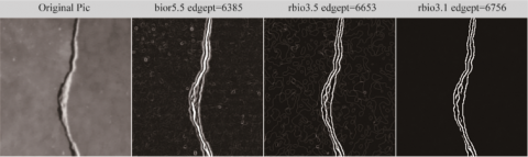
Figure 6 shows the results of edge detection of missile image using wavelets with different high pass decomposition filter characteristics. The decomposition scale is 5 and the initial threshold is 0.18. The three wavelets used in the figure have different high pass filter characteristics. Bior5.5 biorthogonal wavelet has zero even symmetry, and the high pass filters of rbio3.5 wavelet and rbio3.1 wavelet have odd symmetry. However, the sequence elements of high pass decomposition filter of rbio3.5 wavelet are symbol interleaved, which does not meet the characteristics of unidirectional filter, while rbio3.1 wavelet has high pass decomposition unidirectional filter. It can be seen from the detection result graph that for the rbio3.1 wavelet with high pass decomposition filter presenting odd symmetry and sign unidirectionality, complete and clear edge detection results are obtained, while the other two wavelets are not suitable for image edge detection processing.
3.2 Selection of vanishing moment in edge detection
Images contain rich information, and edges will be generated at the location of gray discontinuities such as color, texture and boundary. It is impossible to select vanishing moments through the singularity of images. If the effectiveness of wavelet vanishing moment for singularity detection is considered, when an image is transformed by wavelet, the singularity of the image can be roughly judged by examining the law that the number of modulus maxima points in the detail decomposition coefficient changes with the order of vanishing moment. If the order of a vanishing moment is less than that of the highest singular point of the image, there must be missed detection in the results. When the order of vanishing moment is greater than the highest order of image singular points, the detection completeness is satisfied, and the number of singular points detected should be the largest. As the order of vanishing moment continues to increase, the number of edge points in the detection result will inevitably decrease due to the trend of zero value of detail coefficient. Therefore, the order of vanishing moment with the number of modulus maxima as the peak point can be used as the basis for the selection of wavelet vanishing moment. At the same time, the wavelet with orthogonality has strong decorrelation, so the orthogonal wavelet decomposition is used in the selection of the order of vanishing moment.
Table 3 shows the number of modulus maxima points obtained through the detail decomposition of the airplane image using orthogonal db wavelet family and sym wavelet family. The order of vanishing moment selected by db wavelet family ranges from 1 to 5, and the order range of vanishing moment selected by sym wavelet family is 2~6, and the decomposition scale is 1. It can be seen from the results that the number of modulus maxima points spotted is the most when db wavelet family is db2, while the number of modulus maxima points detected is the most when sym wavelet family is sym2. Both of the detection results show that the singularity of the airplane image is about 2, that is, when the edge detection of the airplane image is carried out, and the order of the vanishing moment of the selected wavelet is greater than 2, the detection completeness can be achieved.
The increase of the order of wavelet vanishing moment can avoid the missing detection, but with the increase of the order of wavelet vanishing moment, the length of wavelet support will inevitably increase, which will make the complexity of edge detection algorithm more complicated. At the same time, the improvement of wavelet vanishing moment will make the detail coefficient of wavelet decomposition tend to zero, resulting in difficulties in the selection of threshold in edge detection. A smaller threshold will delete most of the detail coefficients, making some weak edges of the image unable to be detected. Therefore, if wavelet with high-order vanishing moment is used in edge detection, the threshold calculation should be improved, otherwise the effect of detection will be affected.
Table 3. Relation between the order of vanishing moments and the number of modulus maxima points
|
db wavelet |
dbl |
db2 |
db3 |
db4 |
db5 |
|
order of vanishing moments |
1 |
2 |
3 |
4 |
5 |
|
number of modulus maxima points |
22242 |
22534 |
22508 |
22349 |
22310 |
|
sym wavelet |
sym2 |
sym3 |
sym4 |
sym5 |
sym6 |
|
order of vanishing moments |
2 |
3 |
4 |
5 |
6 |
|
number of modulus maxima points 22534 |
22508 |
22195 |
21832 |
22175 |
|
4.1 Elimination of dislocation
In the process of wavelet edge detection, due to the convolution calculation of the row and column components of wavelet details at various scales and the symmetry of the selected wavelet, certain shifts will occur. The shift caused by convolution is related to the length of the high pass filter, and the shift caused by symmetry is related to the symmetry axis of the filter. In multi-scale edge detection, with the increase of decomposition scale, the shift phenomenon will become more and more serious, which will eventually lead to large edge blur and poor edge positioning ability. Therefore, it is necessary to reverse shift the detail row and column components at each scale to eliminate the influence of convolution, and at the same time, shift compensation is also needed for the edge detection results under each scale.
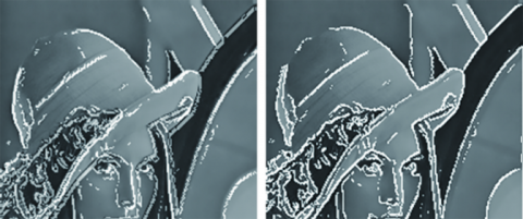
In order to test the accuracy of shift compensation to eliminate dislocation, two algorithms of shift compensation and no-shift compensation are used to carry out modulus maximum edge detection on commonly used Lena image, with a threshold of 0.2 and a decomposition scale of 5. Then the two edge detections are fused with the original Lena image respectively, and the result is shown in Figure 7. The left figure shows the fusion result without shift compensation, and the right figure shows the fusion result after shift compensation. Comparing the white edge line in the image with the position of the original image, such as the brim edge, the crease in the middle of the hat and the edge of the mirror frame, it can be found that the edge image with displacement compensation operation can accurately maintain the edge position of the original image. With the solution of dislocation phenomenon, the selection range of wavelet in edge detection is no longer limited to the filter that is symmetric about zero. Accurate edge detection results can also be obtained for wavelets with symmetry about 1/2.
Figure 7. Test result of eliminating dislocation phenomenon
4.2 Self-adaptive layered threshold algorithm based on information amount and vanishing moment
In wavelet modulus maxima edge detection, there are many modulus maxima points with small amplitude due to weak edges, uneven grayscale or noise. The processing results of these points have a great impact on the visual effect of edge detection. The commonly used threshold processing method is the global threshold, that is, a fixed threshold is selected to compare the image edge modulus maxima points under each scale, and the modulus maxima points smaller than the threshold will be deleted. The global threshold method is simple and easy to implement, but the processing effect is not ideal. If the threshold value is too large, the weak edge of the image will be eliminated at the expense of some details of the image, while if it is too small, some false edges will be retained while retaining the weak edge of the image, and the result is that the subject information of the image is masked.
Considering the characteristics of image wavelet decomposition coefficients, most of the false edges in the image are usually retained in several lower layers of wavelet decomposition detail coefficients. With the increase of decomposition scale, the coefficient value corresponding to the false edges will gradually decrease, while some weak edges of the image will be detected. At this time, the threshold value should be reduced correspondingly to retain more image detail information. In order to realize that the threshold value in edge detection changes with the law of variation of wavelet decomposition detail coefficient, the attenuation speed of layered threshold value is set by the amount of information contained in each layer of wavelet decomposition detail coefficient.
In the threshold selection of edge detection, in addition to considering the variation law of decomposition detail coefficient, the vanishing moment characteristics of the wavelet used should also be displayed. The characteristic of wavelet vanishing moment directly affects the singularity resolution ability of wavelet. Wavelet with high vanishing moment order can detect singular points with great singularity, which is very important for the completeness of image edge detection. However, while ensuring the completeness of detection, the improvement of vanishing moment will also lead to the annihilation of wavelet decomposition detail coefficient, resulting in the difficulty in threshold selection in multi-scale edge detection. For the same detection object, if the threshold thr is appropriate for the kth layer of decomposition detail coefficient of a low-order vanishing moment wavelet, then it is too large for the kth layer of decomposition detail coefficient of a high vanishing moment wavelet and will be deleted, resulting in the loss of weak edge information. Therefore, the order of wavelet vanishing moment should also be considered in the threshold value of each layer of edge detection.
From the above analysis, this paper proposes a self-adaptive layered threshold algorithm based on the amount of information and vanishing moment. The decomposition scale is set as decn, and the initial threshold is set as thr. The vanishing moment of the wavelet used for detection is set as Vn, and the current decomposition layer is set as k. The normalized sequence variance of the detail coefficients of each layer is set as std_dk 1≤k≤decn, std_dk, and then the threshold value of each layer $\operatorname{thr}_{k}$ can be determined by the following formula:
$t h r_{k}$$=\operatorname{van} \times \frac{s t d_{-} d_{1}}{s t d_{-} d_{k}}$$\times \operatorname{thr}\left\{\begin{array}{cc}\text { van }=1 & V n \leq \text { decn } \\ \text { van }=e^{\frac{(1-k)}{V n}} & V n>\text { decn }\end{array}\right.$ (12)
Figure 8 shows the results of edge detection of the airplane image using self-adaptive layered threshold algorithm based on information amount and vanishing moment (left figure) and self-adaptive layered threshold algorithm based on information amount only (right figure). The decomposition scale is 5, the initial threshold is 0.23, the test wavelet is zqwo6.11 biorthogonal wavelet, and the vanishing moment order is 6. From the two edge detection results, it can be seen that the self-adaptive layered threshold algorithm based on the amount of information and vanishing moment has obvious advantages. At points 1, 2 and 3 marked in the left figure, some weak edges of the airplane image can be clearly detected, while the weak edges at these positions in the right figure have been deleted due to the unreasonable threshold.
Figure 8. Effect of threshold processing on high-order vanishing moment wavelet edge detection
4.3 Multi-scale edge weighted fusion algorithm
In multi-scale image edge detection, the image can be decomposed into components at various frequencies, and different scales can detect the local features of the image corresponding to different frequencies. Figure 9 shows the edge detection results of the image airplane on the 1st, 3rd and 5th layer using rbio3.1 wavelet. With the increase of scale and the decrease of threshold, while the false edge of the image is suppressed, some details in the image are gradually detected. However, since the low-frequency information of the image is also gradually reduced with the increase of decomposition layers, there is a large distortion phenomenon in the large scale. When the edges at different scales are detected, the edges at different scales need to be fused to get a complete edge image. In order to take into account the details under large-scale and the overall effect of image edges, the multi-scale edge weighted average method is used to fuse the image edge information at each scale. If edge(i) and edge(i+1) are the edge detection results of two adjacent layers, and d(i) and d(i+1) are weighted values, the total edge after fusion is:
$e d g e=d(i) \times e d g e(i)+d(i+1) \times e d g e(i+1)$ (13)
Figure 9. Edge detection results of the 1st, 3rd and 5th layer using Rbio3.1 wavelet
4.4 Evaluation criteria for edge detection
Image edge is based on people’s visual intuition. Because the information contained in the image is rather different, and different application scenarios will also lead to different requirements for the edge, there is no unified quantitative index that can be used as the evaluation basis for edge detection. However, as an image, the edge cannot have large distortion, otherwise it is unable to meet the requirements of people’s vision, nor can it achieve the accurate positioning of the edge. At the same time, the completeness of edge information in the detection results and the number of edge points obtained are also the basis to measure whether the edge detection method is appropriate. If as much as image edge information can be reflected with fewer edge points, accuracy and efficiency of edge detection can be achieved, which also provides a good foundation for subsequent image processing.
5.1 Edge detection wavelet construction
The optimal requirements for wavelet detection in modulus maximum edge detection are as follows:
(1). The construction of wavelet high pass decomposition filter should have odd symmetry and is symmetric about 1/2 points;
(2). The sequence elements of wavelet high pass decomposition filter are unidirectional;
(3). The support length of the constructed wavelet high pass decomposition filter should not be too long, which is selected within the range of 4~6; the low-pass decomposition filter can be lengthened appropriately in order to maintain better low-frequency approximate information during image multi-scale decomposition;
(4). The order of vanishing moment should meet the requirements of detection completeness.
A wavelet filter bank that meets the requirements of edge detection is designed by using a method of parameterized construction of fixed length compactly supported biorthogonal wavelet. Here, the high-pass decomposition $\tilde{\mathrm{g}}$ and the length of low-pass reconstruction filter h are selected to be 6, namely:
$\tilde{g}=\left\{\tilde{g}_{-2}, \tilde{g}_{-1}, \tilde{g}_{0}, \tilde{g}_{1}, \tilde{g}_{2}, \tilde{g}_{3}\right\} h=\left\{h_{-2}, h_{-1}, h_{0}, h_{1}, h_{2}, h_{3}\right\}$and $h_{k}=(-1)^{k-1} \tilde{g}_{1-k}$
The high pass decomposition filter is set to have odd symmetry, then:
$\tilde{g}_{0}=-\tilde{g}_{1} \quad \tilde{g}_{-1}=-\tilde{g}_{2} \quad \tilde{g}_{-2}=-\tilde{g}_{3}$
In order to limit the proportional relationship of filter elements, the scale factor $k_{1}, k_{2}, k_{1}, k_{2}>0$ is introduced, and the sign function is positive. Now we have:
$\tilde{g}_{1}=k_{1} \tilde{g}_{3} \quad \tilde{g}_{2}=k_{2} \tilde{g}_{3}$
High pass decomposition filter $\tilde{g}$ becomes:
$\tilde{g}=\left\{\tilde{g}_{-2}, \tilde{g}_{-1}, \tilde{g}_{0}, \tilde{g}_{1}, \tilde{g}_{2}, \tilde{g}_{3}\right\}$$=\left\{-\tilde{g}_{3},-k_{2} \tilde{g}_{3},-k_{1} \tilde{g}_{3}, k_{1} \tilde{g}_{3}, k_{2} \tilde{g}_{3}, \tilde{g}_{3}\right\}$
According to the relation of $\widetilde{g}$ and $h$ , the following can be obtained:
$h=\left\{h_{-2}, h_{-1}, h_{0}, h_{1}, h_{2}, h_{3}\right\}$$=\left\{-\tilde{g}_{3}, k_{2} \tilde{g}_{3},-k_{1} \tilde{g}_{3},-k_{1} \tilde{g}_{3}, k_{2} \tilde{g}_{3},-\tilde{g}_{3}\right\}$
Now the length of the low-pass filter $\tilde{h}$ is still set as 6, then we have the following:
$\tilde{h}=\left\{\tilde{h}_{-2}, \tilde{h}_{-1}, \tilde{h}_{0}, \tilde{h}_{1}, \tilde{h}_{2}, \tilde{h}_{3}\right\}=\left\{\tilde{h}_{3}, \tilde{h}_{2}, \tilde{h}_{1}, \tilde{h}_{1}, \tilde{h}_{2}, \tilde{h}_{3}\right\}$
According to the filter condition and complete reconstruction condition, the following can be obtained:
$\left\{\begin{array}{c}L B Q \rightarrow\left\{\begin{array}{c}-\tilde{g}_{3}+k_{2} \tilde{g}_{3}-k_{1} \tilde{g}_{3}=\sqrt{2} / 2 \\ \tilde{h}_{3}+\tilde{h}_{2}+\tilde{h}_{1}=\sqrt{2} / 2\end{array}\right. \\ P R \rightarrow\left\{\begin{array}{c}-\tilde{g}_{3} \tilde{h}_{3}+k_{2} \tilde{g}_{3} \tilde{h}_{2}-k_{1} \tilde{g}_{3} \tilde{h}_{1}=1 / 2 \\ -\tilde{g}_{3} \tilde{h}_{1}+k_{2} \tilde{g}_{3} \tilde{h}_{1}-k_{1} \tilde{g}_{3} \tilde{h}_{2}-k_{1} \tilde{g}_{3} \tilde{h}_{3}=0 \\ \tilde{h}_{2}=k_{2} \tilde{h}_{3}\end{array}\right.\end{array}\right.$ (14)
Since the length of the low-pass decomposition filter $\tilde{h}$ is 6, its vanishing moment order cannot exceed 3. The condition of the third order vanishing moment of low pass decomposition filter $\tilde{h}$ is:
$\left\{\begin{array}{c}1 \text { order } \rightarrow \tilde{h}_{1}=3 \tilde{h}_{2}-5 \tilde{h}_{3} \\ 3 \text { order } \rightarrow \tilde{h}_{1}=9 \tilde{h}_{2}-35 \tilde{h}_{3}\end{array}\right.$ (15)
The condition of the second vanishing moment is the same as that of the first vanishing moment. The following can be obtained when formula (14) and (15) are combined:
$k_{2}=5, k_{1}=\frac{20}{3}, a=-\frac{3 \sqrt{2}}{16}, \tilde{h}_{1}=\frac{5 \sqrt{2}}{16}, \tilde{h}_{2}=\frac{5 \sqrt{2}}{32}, \tilde{h}_{3}=\frac{\sqrt{2}}{32}$
Thus, the biorthogonal wavelet filter bank with support length of 6 and vanishing moment order of 3 can be obtained, which is shown as follows:
$\left\{\begin{array}{c}\tilde{h}=\left\{\frac{\sqrt{2}}{32}, \frac{5 \sqrt{2}}{32}, \frac{5 \sqrt{2}}{16}, \frac{5 \sqrt{2}}{16}, \frac{5 \sqrt{2}}{32}, \frac{\sqrt{2}}{32}\right\} \\ \tilde{g}=\left\{\frac{3 \sqrt{2}}{16}, \frac{15 \sqrt{2}}{16}, \frac{5 \sqrt{2}}{4},-\frac{5 \sqrt{2}}{4},-\frac{15 \sqrt{2}}{16},-\frac{3 \sqrt{2}}{16}\right\} \\ h=\left\{\frac{3 \sqrt{2}}{16},-\frac{15 \sqrt{2}}{16}, \frac{5 \sqrt{2}}{4}, \frac{5 \sqrt{2}}{4},-\frac{15 \sqrt{2}}{16}, \frac{3 \sqrt{2}}{16}\right\} \\ g=\left\{\frac{\sqrt{2}}{32},-\frac{5 \sqrt{2}}{32}, \frac{5 \sqrt{2}}{16},-\frac{5 \sqrt{2}}{16}, \frac{5 \sqrt{2}}{32},-\frac{\sqrt{2}}{32}\right\}\end{array}\right.$ (16)
For the convenience of discussion, this wavelet is named zqwo6.6 biorthogonal wavelet.
In order to obtain higher-order vanishing moment at the decomposition end, it is necessary to increase the support length of low-pass decomposition filter $\tilde{h}$ . The high pass decomposition $\tilde{g}$ and the low-pass reconstruction filter h remain unchanged, and the support length of the filter $\tilde{h}$ increases by 10, then:
$\tilde{h}=\left\{\tilde{h}_{-4}, \cdots, \tilde{h}_{-1}, \tilde{h}_{0}, \tilde{h}_{1}, \cdots, \tilde{h}_{5}\right\}$
$\stackrel{\text { even symmetry }}{\longrightarrow}\left\{\tilde{h}_{5}, \cdots, \tilde{h}_{1}, \tilde{h}_{1}, \cdots, \tilde{h}_{5}\right\}$
The construction method is exactly the same as that of zqwo6.6 biorthogonal wavelet. The equations of vanishing moment relations of the first five order are as follows:
$\left\{\begin{array}{c}\text { 1order, 2order } \rightarrow \tilde{h}_{1}=3 \tilde{h}_{2}-5 \tilde{h}_{3}+7 \tilde{h}_{4}-9 \tilde{h}_{5} \\ \text { 3order } \rightarrow \tilde{h}_{1}=9 \tilde{h}_{2}-35 \tilde{h}_{3}+91 \tilde{h}_{4}-189 \tilde{h}_{5} \\ \text { 4order } \rightarrow \tilde{h}_{1}=15 \tilde{h}_{2}-65 \tilde{h}_{3}+175 \tilde{h}_{4}-369 \tilde{h}_{5} \\ \text { 5order } \rightarrow \tilde{h}_{1}=33 \tilde{h}_{2}-275 \tilde{h}_{3}+1267 \tilde{h}_{4}-4149 \tilde{h}_{5}\end{array}\right.$ (17)
The relation equations of filter condition of the wavelet to be constructed and complete reconstruction condition of the wavelet are:
$\left\{\begin{array}{c}L B Q \rightarrow\left\{\begin{array}{c}-\tilde{g}_{3}+k_{2} \tilde{g}_{3}-k_{1} \tilde{g}_{3}=\frac{\sqrt{2}}{2} \\ \tilde{h}_{5}+\tilde{h}_{4}+\tilde{h}_{3}+\tilde{h}_{2}+\tilde{h}_{1}=\frac{\sqrt{2}}{2}\end{array}\right. \\ P R \rightarrow\left\{\begin{array}{c}-\tilde{g}_{3} \tilde{h}_{3}+k_{2} \tilde{g}_{3} \tilde{h}_{2}-k_{1} \tilde{g}_{3} \tilde{h}_{1}=1 / 2 \\ -\tilde{g}_{3} \tilde{h}_{1}+k_{2} \tilde{g}_{3} \tilde{h}_{1}-k_{1} \tilde{g}_{3} \tilde{h}_{2}-k_{1} \tilde{g}_{3} \tilde{h}_{3}+k_{2} \tilde{g}_{3} \tilde{h}_{4}-\tilde{g}_{3} \tilde{h}_{5}=0 \\ -\tilde{g}_{3} \tilde{h}_{2}+k_{2} \tilde{g}_{3} \tilde{h}_{3}-k_{1} \tilde{g}_{3} \tilde{h}_{4}-k_{1} \tilde{g}_{3} \tilde{h}_{5}=0 \\ \tilde{h}_{4}=k_{2} \tilde{h}_{5}\end{array}\right.\end{array}\right.$ (18)
When the vanishing moment order of the wavelet to be constructed is selected as 3, the following filter banks can be obtained:
$\left\{\begin{array}{c}\tilde{h}=\{0.037347,0.04247,-0.13402,0.032512,0.7288,0.7288, \cdots\} \\ \tilde{g}=\{0.21595,0.24558,0.73673,-0.73673,-0.24558,-0.21595\} \\ h=\{0.21595,-0.24558,0.73673,0.73673,-0.24558,0.21595\} \\ g=\{0.037347,-0.04247,-0.13402,-0.032512,0.7288,-0.7288, \cdots\}\end{array}\right.$ (19)
For the convenience of discussion, this wavelet is named as zqwo6.10 biorthogonal wavelet. When the vanishing moment order of the wavelet to be constructed is chosen as 6, the following filter bank can be obtained:
$\tilde{h}=\{-2.7674 e-005,0.017379,0.12091,0.36063,0.20822,0.20822, \cdots\}$
$\tilde{g}=\{-0.00018802,0.11808,0.82537,-0.82537,-0.11808,0.00018802\}$
$h=\{-0.00018802,-0.11808,0.82537,0.82537,-0.11808,-0.00018802\}$
$g=\{-2.7674 e-005,-0.017379,0.12091,-0.36063,0.20822,-0.20822, \cdots\}$ (20)
For the convenience of discussion, this wavelet is named as zqwo6.11 biorthogonal wavelet. It can be seen from the filter banks of the three biorthogonal wavelets that all the three wavelets have odd symmetry, and the high pass decomposition filters of zqwo6.6 and zqwo6.10 biorthogonal wavelets are symbolic unidirectional filters, while zqwo6.11 biorthogonal wavelets do not have this property.
Figure 10 and Figure 11 show the waveforms of high pass decomposition filter and low pass decomposition filter of the three wavelets respectively. From the figure, it can be seen that zqwo6.6 biorthogonal wavelet has the best smoothness and the fastest attenuation, and the sequence element difference on both sides of the symmetry axis of its high pass decomposition filter is the largest; Although the high pass decomposition filter of zqwo6.10 wavelet has sign unipolarity, the smoothness of wavelet is poor; zqwo6.11 wavelet has the highest vanishing moment, and its smoothness is better than that of zqwo6.10 wavelet. The low-pass decomposition filter has a long support length, and the attenuation speed is the slowest among the three wavelets. The high pass decomposition filter does not meet the sign unidirectionality.
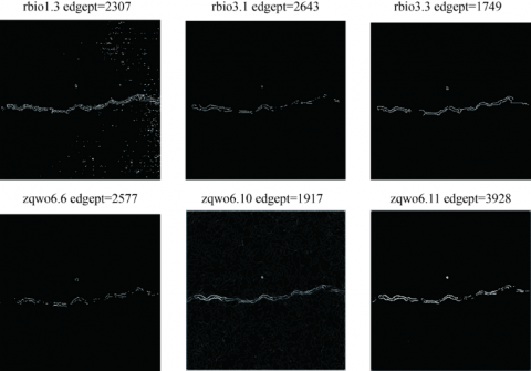
In order to test the edge detection performance of the constructed wavelet, Matlab is used as a simulation tool to detect the edge of four images of ultra-high arch dam concrete specimens, and rbio3.3, rbio1.3 and rbio3.1 biorthogonal wavelets are selected for test and comparison (Figure 12). The high pass decomposition filters of the six wavelets used in the test have odd symmetric properties. Among them, the high pass decomposition filters of rbio3.3 and rbio1.3 wavelets do not have sign unidirectionality, and the low pass filters have the main characteristics of the six wavelets used in the test. In all edge detection examples, the threshold value is determined by the adaptive layered threshold denoising algorithm based on the amount of information and vanishing moment, and the edges of each scale are merged using the weighted fusion algorithm (Table 4).
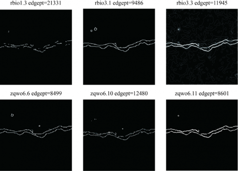
Figure 13, Figure 14 and Figure 15 respectively show the edge detection results of each wavelet on Crack1, Crack2 and Crack3. The decomposition scale is 5, and the initial threshold values are 0.23, 0.7 and 0.3 respectively. The threshold values of each layer are calculated by self-adaptive stratified threshold algorithm. The variable edgept in the figure is the number of edge points in the detection results.
Figure 10. Comparison of waveforms of zqwo6.6, 6.10 and 6.11 wavelet high-pass decomposition filters
Figure 11. Comparison of waveforms of zqwo6.6, 6.10 and 6.11 wavelet high-pass decomposition filters
5.2 Simulation examples and analysis
Figure 12. Four original crack images by wavelet edge detection
Table 4. Main characteristics of wavelet used in edge detection
|
Property of wavelet |
Low pass decomposition filter |
High pass decomposition filter |
|||||
|
length |
attenuating property |
vanishing moment |
symmetry |
length |
Variance of element at each side of the center |
Unidirectionality of sign |
|
|
rbio1.3 |
2 |
No |
1 |
Odd symmetry |
6 |
1.414 |
Interlaced |
|
rbio3.3 |
4 |
Relatively slow |
3 |
Odd symmetry |
8 |
1.9887 |
Interlaced |
|
rbio3.1 |
4 |
Relatively slow |
3 |
Odd symmetry |
4 |
2.1214 |
Yes |
|
zqwo6.6 |
6 |
Relatively fast |
3 |
Odd symmetry |
6 |
3.5356 |
Yes |
|
zqwo6.10 |
10 |
fast |
3 |
Odd symmetry |
6 |
1.4735 |
Yes |
|
zqwo6.11 |
10 |
Relatively slow |
6 |
Odd symmetry |
6 |
1.6507 |
Yes |
Image Crack1, Crack2 and Crack3 are relatively simple. From the edge detection results, it can be seen that the detection results of rbio3.3 and rbio1.3 wavelets are the worst, and the edges in the detection results are very fuzzy. The other four wavelets can basically detect the edge information of the main body of the space shuttle, and the edge location is accurate, which shows that the high pass decomposition filter of edge detection wavelet must have odd symmetry, and the sequence elements meet the requirement of sign unidirectionality. From the perspective of low-pass decomposition filter, the longer filter support can better maintain the low-frequency information of the image in multi-scale decomposition. Therefore, more weak edge information of the image can be obtained in the edge detection results of zqwo6.11 wavelet. In contrast, the vanishing moment of zqwo6.10 wavelet is 3 and its smoothness is poor. Although it has the same support length as zqwo6.11 wavelet, the vanishing moment of zqwo6.11 wavelet is 6. Because the detail coefficient of the high-order vanishing moment presents the trend of annihilation, under the same initial threshold value and hierarchical threshold value algorithm, the number of edge points detected by zqwo6.10 wavelet is much larger than that of zqwo6.11 wavelet. Comparing rbio3.1, zqwo6.6 and zqwo6.10 wavelets whose vanishing moment order are all 3, the detection results of rbio3.1 and zqwo6.6 wavelets with good filter smoothness are better than zqwo6.10 wavelets. From the edge detection results of each wavelet, it can be seen that the detection efficiency of zqwo6.6 wavelet and zqwo6.11 wavelet is the highest. The number of edge points detected by both wavelets is much smaller than that detected by other wavelets, but the detection effect is not weakened. In the detection results of other wavelets, in addition to effective edge points, there are many false edge points.
Figure 16 shows the results of edge detection on the test image Crack4 by each wavelet The decomposition scale is 5, and the initial threshold is 0.23 respectively. The thresholds of each layer are calculated by using the self-adaptive layered threshold algorithm. The variable edgept in the figure is the number of edge points in the detection results. The test image plane4 is the aerial image of an airliner. The outline of the aircraft is fused with the background of mountains and clouds, and the image contains rich details. Observing the edge detection results of each wavelet, the edge detection results of rbio3.3 and rbio1.3 wavelets are very fuzzy, and the contour edge of the aircraft cannot be clearly distinguished from the edge of the background mountain. The detection result of zqwo6.10 wavelet is better than that of the first two wavelets, but the location edge of mountains and other complex details is still not very clear. Like the previous three test images, the detection results of rbio3.1, zqwo6.6 and zqwo6.11 wavelets are still the best, and the number of detected edge points of zqwo6.6 wavelet is significantly less than that of other wavelets, that is, zqwo6.6 wavelet has the best edge detection effectiveness.
The simulation examples of edge detection of the above four test images prove the correctness of the analysis of wavelet characteristics in image edge detection with wavelet modulus maxima in this chapter, that is, the wavelet high pass decomposition filter for edge detection must have the characteristics of odd symmetry and sign unidirectionality. The test results show that the three wavelets zqwo6.6, zqwo6.10 and zqwo6.11 constructed in this paper all have good edge detection ability. The self-adaptive hierarchical threshold algorithm based on information amount and vanishing moment is applied to the edge detection process of simple images and complex images, and good results have been attained.
Figure 13. Comparison of results of edge detection of concrete Crack1 image by test wavelet
Figure 14. Comparison of results of edge detection of concrete Crack2 image by test wavelet
Figure 15. Comparison of results of edge detection of concrete Crack3 image by test wavelet
Figure 16. Comparison of results of edge detection of concrete Crack4 image by test wavelet
Starting from the purpose of image edge detection, this paper briefly analyzes the shortcomings of traditional edge detection algorithms. By analyzing the manifestation of edges in wavelet decomposition, the flow of edge detection algorithm based on wavelet modulus maxima is provided. The dislocation phenomenon, threshold selection and multi-scale edge fusion in modulus maxima edge detection algorithm are studied. An improved self-adaptive layered threshold algorithm based on information amount and vanishing moment and a weighted multi-scale edge fusion algorithm are proposed. Based on the symmetry of wavelet, the composition of filter and vanishing moment, this paper studies the influence of wavelet characteristics on image edge detection, and puts forward the main conditions of wavelet construction and the evaluation criteria of edge detection. Based on the parametric method of construction of fixed length compactly supported biorthogonal wavelets, zqwo6.6, zqwo6.10 and zqwo6.11 biorthogonal wavelets with high pass decomposition filter having odd symmetry and filter sequence presenting unidirectionality are constructed, and their edge detection capabilities are compared through simulation examples, with ideal effects achieved.
The author was endowed by Water Conservancy Science and Technology Plan Project of Shaanxi Province (Grant No.: 2019slkj-19).
[1] Mathew, A., Chackravarthi, S.A. (2013). Edge detection in speckled SAR images using SWT and multiscale product. In 2013 7th International Conference on Intelligent Systems and Control (ISCO), pp. 316-320. https://doi.org/10.1109/ISCO.2013.6481170
[2] Manish, T.I., Murugan, D., Kumar, T.G. (2012). Edge detection by combined Canny filter with scale multiplication & ant colony optimization. In Proceedings of the Second International Conference on Computational Science, Engineering and Information Technology, 497-500. https://doi.org/10.1145/2393216.2393299
[3] Hsia, C.H., Lin, T.Y., Chiang, J.S. (2020). An adaptive binarization method for cost-efficient document image system in wavelet domain. Journal of Imaging Science and Technology, 64(3): 30401-1. https://doi.org/10.2352/J.ImagingSci.Technol.2020.64.3.030401
[4] Strela, V., Portilla, J., Simoncelli, E.P. (2000). Image denoising using a local Gaussian scale mixture model in the wavelet domain. In Wavelet Applications in Signal and Image Processing VIII, 4119: 363-371. https://doi.org/10.1117/12.408621
[5] Kim, S., Kim, D., Kim, T.C., Hayes, M., Paik, J. (2012). Selective frequency decomposition in the wavelet domain for single image-based super-resolution. In 2012 IEEE International Conference on Consumer Electronics (ICCE), pp. 124-125. https://doi.org/10.1109/ICCE.2012.6161771
[6] Das, S., Mukherjee, S., Majumdar, B., Pipplai, A. (2013). Notice of Violation of IEEE Publication Principles: A Gravitational Search based Fuzzy Approach for Edge Detection in Colour and Grayscale Images. IEEE Transactions on Fuzzy Systems. https://doi.org/10.1109/TFUZZ.2013.2286418
[7] Karande, K.J. (2012). Multiscale wavelet based edge detection and Independent Component Analysis (ICA) for Face Recognition. In 2012 International Conference on Communication, Information & Computing Technology (ICCICT), pp. 1-5. https://doi.org/10.1109/ICCICT.2012.6398140
[8] Garg, S., Mathur, M. (2014). Chaotic map based steganography of gray scale images in wavelet domain. In 2014 International Conference on Signal Processing and Integrated Networks (SPIN), pp. 689-694. https://doi.org/10.1109/SPIN.2014.6777043
[9] Jain, P., Tyagi, V. (2017). An adaptive edge-preserving image denoising technique using patch-based weighted-SVD filtering in wavelet domain. Multimedia Tools and Applications, 76(2): 1659-1679. https://doi.org/10.1007/s11042-015-3154-8
[10] Charaâ, S., Ellouze, N. (2014). Multiscale product edge detection in different colour spaces. In 2014 11th International Conference on Information Technology: New Generations, 660-664. https://doi.org/10.1109/ITNG.2014.103
[11] Kumar, K., Mustafa, N., Li, J.P., Shaikh, R.A., Khan, S.A., Khan, A. (2014). Image edge detection scheme using wavelet transform. In 2014 11th International Computer Conference on Wavelet Actiev Media Technology and Information Processing (ICCWAMTIP), pp. 261-265. https://doi.org/10.1109/ICCWAMTIP.2014.7073404
[12] Ghosh, A., Chatterjee, A., Roy, A., Mukherjee, A., Naskar, M.K. (2018). Snickometer edge detection by feature extraction in TF plane and wavelet domain. In 2018 IEEE Applied Signal Processing Conference (ASPCON) pp. 143-148. https://doi.org/10.1109/ASPCON.2018.8748535
[13] Tsiotsios, C., Petrou, M. (2013). On the choice of the parameters for anisotropic diffusion in image processing. Pattern Recognition, 46(5): 1369-1381. https://doi.org/10.1016/j.patcog.2012.11.012
[14] Charaâ, S., Ellouze, N. (2014). Multiscale product riesz wavelet for color edge detection in Hilbert domain. In 2014 European Modelling Symposium, pp. 215-220. https://doi.org/10.1109/EMS.2014.77
[15] El-Khamy, S.E., Abdel-Malek, M.B., Kamel, S.H. (2013). C9. A new wideband spectrum sensing technique based on compressive sensing, wavelet edge detection and parallel processing. In 2013 30th National Radio Science Conference (NRSC), pp. 202-210. https://doi.org/10.1109/NRSC.2013.6587945
[16] Cho, W., Jeon, J. (2015). Edge detection in wavelet transform domain. In 2015 21st Korea-Japan Joint Workshop on Frontiers of Computer Vision (FCV), pp. 1-4. https://doi.org/10.1109/FCV.2015.7103718
[17] Edi, F., Ginting, K., Hartati, S., Purba, R.A. (2021). Edge detection to make drawing sketch using Laplacian operator and Gabor wavelet for learning devices. In Journal of Physics: Conference Series, 1764(1): 012070. https://doi.org/10.1088/1742-6596/1764/1/012070
[18] Anam, C., Haryanto, F., Widita, R., Arif, I. (2015). New noise reduction method for reducing CT scan dose: Combining Wiener filtering and edge detection algorithm. In AIP Conference Proceedings, 1677(1): 040004. https://doi.org/10.1063/1.4930648
[19] Chambers, B.J., Reynolds Jr, W.D., Campbell, D.S., Fennell, D.K., Ansari, R. (2007). Wavelet-based target detection using multiscale directional analysis. In Automatic Target Recognition XVII, 6566: 57-66. https://doi.org/10.1117/12.720985
[20] Govindarajan, B., Panetta, K., Agaian, S. (2008). Progressive edge detection on multi-bit images using polynomial-based binarization. In Proc. of the ICMLC, pp. 3714-3719. https://doi.org/10.1109/ICMLC.2008.4621051