Feifei Wang* | Haifeng Hu
OPEN ACCESS
The existing clustering routing protocols face imbalanced energy consumption and the hot-spot problem. To solve the problems, this paper proposes an energy-efficient unequal clustering routing algorithm (UCRA). Firstly, the monitoring area was divided by concentric circles into rings of different sizes. Next, the cluster heads were elected based on position and residual energy. Before clustering, each common sensor joins a cluster based on the electability of each cluster head. The electability is defined based on the residual energy of the cluster head and the distance from the cluster head to the centerline of the ring of the common sensor. For multi-hop routing from a cluster head to the base station, the routing sensor was selected dynamically based on the local ring of the cluster head and the residual energy of neighboring cluster heads. The simulation results show that the UCRA can effectively solve the hot-spot problem in uniform clustering routing protocols, balance the energy consumption of network sensors, and extend the network lifecycle.
wireless sensor network (WSN), cluster routing, hot-spot problem, lifecycle
The wireless sensor network (WSN) is a self-organized network of multiple sensors with functions like wireless communication, information sensing, data processing and data transmission. The WSN has been widely applied in such fields as military, environmental monitoring, wisdom medicine and smart home. However, the application of the WSN is limited to special environments, because the sensors are too small to carry lots of energy or refuel energy easily. Therefore, it is a research hotspot to complete tasks through collaboration between the sensors with limited energy. In the WSN, the routing protocol plays a critical role in balancing and reducing the energy consumption of sensors in data collection and transmission. The existing routing protocols adopt either planar routing or clustering routing. Comparatively, clustering routing can easily adopt to system changes and prevent long-distance data transmission. Therefore, many scholars on the WSN have attempted to explore and improve clustering routing protocols [1-9]. Below is a brief review of the existing clustering routing protocols.
Heinzelman et al. [10] put forward a mechanism of dynamic cluster head election and cluster head rotation. This mechanism improves the routing performance, but still faces problems like the randomness in cluster head selection and the one-hop communication between cluster head and the base station. Many algorithms have emerged to solve the problems, namely, the centralized low-energy adaptive clustering hierarchy (LEACH-C) [11] and hybrid, energy-efficient, distributed (HEED) clustering algorithm [12]. These algorithms can effectively reduce the energy consumption of sensors and extend the network lifecycle. However, all of them assume that the data are allocated uniformly into clusters of the same size. If it lies close to the base station, a cluster head needs to receive and forward the data from cluster heads far away from the base station, in addition to sending the data of the local cluster. Hence, the sensor close to the base station often die early due to energy depletion, creating the hot-spot problem. To overcome this problem, Soro and Heinzelman [13] proposed an unequal clustering method, in which the cluster size is negatively correlated with the distance between the cluster head and base station. Nevertheless, this method is not suitable for networks with randomly deployed sensors, because its cluster heads must be placed in preset positions. Li et al. [14] computed the competition radius of each sensor based on sensor position, and ensured that a cluster far away from the base station is larger than that close to the base station. Despite balancing the energy consumption among the sensors, Li’s approach fails to consider the residual energy of each sensor and the selection of the transit sensor for the next hop communication of the cluster head.
Considering the above problems, this paper fully explores the routing of the WSN, and develops an energy-efficient unequal clustering routing algorithm (UCRA). Before route construction, the UCRA initializes the network and divides it into several rings by concentric circles. During cluster head election, the electability of each sensor is computed based on its residual energy and its distance to the base station. In the clustering phase, each sensor joins a suitable cluster based on its local ring and the distance between the cluster head and the centerline of the ring. To set up the route between cluster heads, the transit sensors are selected through overall consideration of the sensor energy and the local ring. In the same cluster, the data are transmitted in a single hop. The UCRA can effectively balance the energy consumption of network sensors and extend the WSN lifecycle.
The remainder of this paper is organized into five parts: Section 2 reviews the classic routing protocols, and models the network and energy of the UCRA; Section 3 introduces the network initialization, cluster head election, clustering and routing of the UCRA; Section 4 compares the UCRA, the low-energy adaptive clustering hierarchy (LEACH) and the energy-efficient unequal clustering algorithm (EEUC) through simulation in terms of the energy consumption and the number of surviving sensors; Section 5 sums up the research findings.
2.1 Classic routing protocols
The LEACH is the earliest clustering routing protocol. In this protocol, the cluster heads are elected dynamically, and the sensors take turns to serve as cluster heads. If a sensor has served as cluster head, its electability T(n) will be set to zero and it will not be elected again in this round. If a sensor has not served as a cluster head, it will be elected at the probability of T(n):
$T(n)=\left\{\begin{array}{ll}{\frac{\mathrm{p}}{1-p[r \bmod (1 / p)]}} & {\text { if } n \in G} \\ {0} & {\text { otherwise }}\end{array}\right.$ (1)
The sensor will generate a random number, RN, in the interval of [0, 1]. If RN<T(n), the sensor will be elected. The elected sensor will broadcast the election result across the network. Then, common sensors will join a suitable cluster based on the signal intensity. The LEACH can balance the energy consumption between sensors to a certain extent, and outperform the planar routing protocols. However, the randomly elected cluster heads are not distributed uniformly across the network, and the energy is consumed rapidly through the direct communication between cluster heads and the base station.
The EEUC sets a threshold to determine candidate cluster heads. The candidates remain in the working state, while the other sensors enter the sleep mode. Then, each candidate broadcasts its message within its competition radius, and constructs a set of neighboring candidates based on the messages received from the other candidates. If a candidate declares that it has become the cluster head, all its neighboring candidates will exit the election and become common sensors. After the election, the sleeping sensors are awakened for clustering. Each common sensor will join the cluster of the head with the highest signal intensity. For inter-cluster routing, the next-hop sensor is selected based on the minimal sum of the squares of the distance between the current head and a neighboring head and that between the current head and the base station. The EEUC can effectively solve the hot-spot problem induced by multi-hop routing between clusters. However, the random election of cluster heads, coupled with the fixed routes, may cause cluster heads to lack energy and the transit sensors to consume energy too quickly.
2.2 System modelling
It is assumed that N sensors are deployed randomly in an M×M area, and periodically collect and transmit data. The set of all sensors can be expressed as S={S1,S2,...SN}, |S|=N, with Si being the i-th sensor. The WSN satisfies the following hypotheses:
(1) The base station lies outside the monitoring area. The base station and all sensors will not move after being deployed. The base station has unlimited energy.
(2) Every sensor has limited energy, the same structure, a unique ID in the network, and the ability to fuse data.
(3) To reduce energy consumption, every sensor can adjust its transmitting power based on its distance to the message receiver.
(4) The channels are symmetric. If the transmitting power of a sensor is known, then the distance between the sensor and the sender can be approximated based on the received signal strength indicator (RSSI) [15].
(5) Every sensor can direct communicate with the base station or indirectly via the other sensors.
The UCRA uses the wireless communication energy consumption model proposed by Heinzelman et al. [10]. The energy ETx(k,d) consumed by a sensor to send k bit data to a sensor or the base station over the distance d can be computed by:
$E_{T_{X}}(k, d)=\left\{\begin{array}{ll}{k^{*} E_{e l e c}+k^{*} \xi_{f s} * d^{2}} & {d<d_{0}} \\ {k^{*} E_{e l e c}+k^{*} \xi_{q m p} * d^{4}} & {d \geq d_{0}}\end{array}\right.$ (2)
The energy ERx(k) consumed by a sensor to receive k bit data can be calculated by:
$E_{R x}(k)=k^{*} E_{e l e c}$ (3)
According to formulas (2) and (3), more energy is needed for a sensor to send an amount of data than to receive that amount of data. Therefore, data fusion at each cluster head helps to reduce the amount of data to be sent. Suppose the data collected by a cluster head is redundant. The energy consumed by the cluster head to fuse the n bit data from the m cluster members can be expressed as:
$E_{D \mathrm{f}}(m, n)=m^{*} E_{D A} * n$ (4)
where, EDA is the fusion coefficient of the UCRA. While reducing the amount of data to be sent, the data fusion itself may consume a certain amount of energy.
To eliminate the hot-spot problem in the WSN, the UCRA firstly initializes the network and divides the monitoring area into several rings by concentric circles. The cluster head election, clustering and routing were conducted based on the division.
3.1 Network initialization
During initialization, the base station computes the minimum distance dmin and maximum distance dmax to the monitoring area, and then broadcasts a signal across the network. Upon receiving the signal, each sensor will compute it approximate distance to the base station based on the RSSI.
In addition, the monitoring area was divided into several rings by concentric circles. The circles closer to the base station has relatively small radii. The number of rings can be computed by:
$\mathrm{n}=\left(d_{\max }-d_{\min }\right) / d_{0}$ (5)
where, d0 is a threshold, i.e. the width Rmax of the most far away ring from the base station. From the network center to the base station, the widths of rings form an ascending series. Then, the relationship between the width Rmin of the closet ring to the base station and Rmax can be described as:
$R_{\max }=R_{\min }+(n-1)^{*} d=R_{\min }+\left(\frac{R_{\max }-R_{\min }}{d_{0}}-1\right) * d$ (6)
Let Rmin=c*Rmax, where c is a variable. The d value can be determined after c. Then, the width of each ring (R1, R2,..., Rn) and the distance from the centerline of the ring to the base station can be determined. Next, the base station will broadcast its distances to the outer edge, inner edge and centerline of each ring across the network.
3.2 Cluster head election and clustering
During the election of cluster heads, each sensor compares its distance to the base station dtoBS with the received message on the rings, and determines which ring to join. Then, the countdown timer of the sensor can be constructed based on the width of the ring Ri and the residual energy of the sensor ERe:
$S_{i} \cdot T=T^{*}\left[(1-\partial)^{*}\left(1-\frac{E_{\mathrm{Re}}}{E_{\text {lnit }}}\right)+\partial^{*}\left(\frac{\left|S_{i} \cdot d_{t o B S}-S_{i} \cdot R_{\text {center}}\right|}{S_{i} \cdot R_{i}}\right)\right]$ (7)
where, ERe is the current residual energy of the sensor; EInit is the initial energy of the sensor; Si.dtoBS is the distance between sensor Siand the base station; Si.Rcenter is the distance from the centerline of the local ring of the sensor to the base station.
At the beginning of the election, all sensors are candidates and start their timers. Each candidate broadcasts a message with the width of the local ring Ri(i=1~n) as the radius. If a candidate receives the message from another candidate before the end of its countdown, it will immediately exit the election and become a common sensor. Otherwise, the candidate will become a cluster head.
After the election, all cluster heads will broadcast a message, including its ID, current residual energy ERe and the ID of the local ring RID, with the width of the local ring Ri as the radius. Upon receiving the message, a common sensor will join the cluster of the head in its local ring. If the common sensor receives the messages from several heads in its local ring, it will join the cluster of the head with the largest Pi value:
$P_{i}=c * \frac{E_{\mathrm{Re}}}{E_{\text {Init }}}+(1-c)^{*}\left(1-\frac{\left|S_{i} \cdot d_{\text {toBS }}-S_{i} \cdot R_{\text {coutar}}\right|}{S_{i} \cdot R_{i}}\right)$(8)
It takes much energy to form a cluster. Thus, it is unwise to perform clustering each round. Therefore, the UCRA predicts the energy of a sensor at a moment by the method proposed by Li et al. [16]. The clusters will be reestablished if this energy is below a certain value.
3.3 Routing
In the WSN, data transmission either occurs within the cluster or between cluster heads. In the UCRA, the transmission range is controlled in network division and clustering. Thus, each cluster member can directly transmit data to its cluster head; then, each cluster head will fuse all the received data before transmitting it to the base station through multi-hop routing via the other cluster heads.
Before setting up the inter-cluster routes, each cluster head needs to maintain a set of neighboring cluster heads, NC. Firstly, the base station broadcast a message, HELLO_MSG. After receiving the message, each sensor whose monitoring area falls in the first ring will add the message into its own Si.NC, and then send a new message, including the ID of the local cluster head, its residual energy and the ID of its local ring, Si.RID, with threshold d0 as the radius. Any cluster head Sj that receives the new message will firstly judge if Sj.RID=Si.RID+1 is valid. If yes, the cluster head Sj will add Si into its set of neighboring cluster heads. Next, the cluster head Sj will broadcast a message, including its ID, its residual energy and the ID of its local ring, Sj.RID, with threshold d0 as the radius. Then, any cluster head that receives the message will add the sender into its own set of neighboring cluster heads, if the sender satisfies the judgement criterion. This process will repeat until all the cluster heads in the most faraway rings from the base station have set up their own sets of neighboring cluster heads.
During data transmission, each cluster head selects a suitable member from its set of neighboring cluster heads as the transit sensor. The selection criterion is depicted as follows:
Let Si be a cluster head not in the first ring, and Sj be a member of Si’s set of neighboring cluster heads. Suppose Si needs to transmit data to the base station. Then, the energy consumed by Si to transmit k bit data to the Sj can be computed by:
$E\left(S_{i}, S_{j}\right)=E_{\text {elec}} * k+\xi_{\text {amp}} * k^{*} d^{2}\left(S_{i}, S_{j}\right)$ (9)
The energy consumed by Sj to receive the k bit data and forward it to the base station, plus that consumed by the base station to receive the data, can be computed by:
$E\left(S_{j}, B S\right)=E_{e l e c} * k+E_{e l e c} * k+\xi_{a n p} * k^{*} d^{2}\left(S_{j}, B S\right)$ (10)
Thus, the total energy consumed to transmit k bit data from Si to the base station via Sj can be computed by:
$E_{\text {total }}=E\left(S_{i}, S_{j}\right)+E\left(S_{j}, B S\right)$
$=3^{*} E_{\text {elec }} * k+\xi_{\text {anp }} * k^{*}\left[d^{2}\left(S_{i}, S_{j}\right)+d^{2}\left(S_{j}, B S\right)\right]$ (11)
The total energy consumed to transmit k bit data from Sidirectly to the base station can be computed by:
$E_{\mathrm{toBS}}=E_{e l e c} * k+\xi_{\operatorname{amp}} * k^{*} d^{\beta}\left(S_{i}, \mathrm{BS}\right)$ (12)
If distance d is smaller than the threshold, β equals 2; otherwise, β equals 4. During data transmission, the energy consumption of a cluster head mainly comes from ξamp*k*dβ. Therefore, d2(Si,Sj)+d2(Sj,BS) should be compared with dβ(Si,BS).
If d2(Si,Sj)+d2(Sj,BS)< dβ(Si,BS), Sj should serve as the transit sensor of Si and join the set of transit sensors, Si.RC. If several sensors satisfy this judgement criterion, the sensor with the most residual energy should be selected. If no sensor satisfies this criterion, the set of neighboring cluster heads should be taken as the set of transit sensors. After the set of transit sensors is constructed, the set of neighboring cluster heads should be emptied.
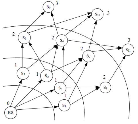
The inter-cluster routing of the UCRA is explained by Figures 1-3 below.
Figure 1. Distirbution of the base station and cluster heads in a WSN
Figure 1 shows a WSN consisting of one base station and 11 cluster heads S1, S2, S3, ...S11. Each dotted line stands for the wireless two-way link between two cluster heads. The number besides each dotted line is the identifier of the local ring of the cluster heads RID. The RID of S1, S2, S3 and S4 is 1, the RID of S5, S6, S7 and S8 is 2, the RID of S9, S10 and S11 is 3, and the RIDof the base station is zero.
Figrue 2. The neighboring cluster heads of each head
In Figure 2, each solid arrow means the data sent to the target node are transmitted from the current ring to the next ring.
To establish the set of neighhoring cluster heads, the base station firstly broadcasts a message. The cluster heads of the first ring S1, S2, S3 and S4 will then receive the message. Since the RID of S1, S2, S3 and S4is 1, the following equations are valid: S1.RID=BS.RID+1, S2.RID=BS.RID+1, S3.RID=BS.RID+1 and S4.RID=BS.RID+1. Therefore, the base station is added to the set of neighboring nodes of S1, S2, S3 and S4.
Next, S1, S2, S3 and S4 each sets up a new message containing its ID, residual energy and RID, and broadcasts the new message. Any cluster head receiving the new message will judge whether to update its set of neighboring cluster heads. Here, S6 is cited to explain the judgement process. Upon receiving the message from S1, S6 will first verify the validity of S6.RID=S1.RID+1. If the equation is valid, S6 will add S1 to its set of neighboring cluster heads, and set up and broadcast a new message. Because it also falls within the communication radius of S2 and S3, S6 can receive the messages from S2 and S3, too. If S6.RID=S2.RID+1 and S6.RID=S3.RID+1 are valid, S2 and S3 will also be added to the set of neighboring cluster heads of S6.
Sometimes, the message may be received by a cluster head within the same ring of the broadcaster or in a ring close to the base station. For example, if S3 receives the message from S2, it will not be added to the set of neighboring cluster heads of S2, because S3.RID<S2.RID+1. The same process is executed by each cluster head. In this way, each cluster head can establish its own set of neighboring cluster heads.
Figure 3. Transit sensors of each cluster head
The next step is to build the set of transit sensors of each cluster head (Figure 3), according to the acquisition method of this type of set in the UCRA. Taking cluster head S7 for example: the set of neighboring cluster heads of S7 is S7.NC={S2, S3, S4}. Suppose d2(S7, S2)+d2(S2, BS)<d2(S7, BS), d2(S7, S3)+d2(S3, BS)<d2(S7, BS) and d2(S7, S4)+d2(S4, BS)>d2(S7, BS). Then, S2 and S3 will be added to the set of transit sensors of S7. The same process is executed by each cluster head to create the corresponding set of transit sensors.
Figures 1-3 explain how a cluster head in a simple WSN establishes its set of neighboring cluster heads and set of transit sensors. In actual WSNs, the numerous sensors are densely distributed, and each cluster head has many transit sensors. During data transmission, a cluster head only needs to dynamically select from a set of candidate transit sensors. In this way, the network security is improved because the attacker is unlikely to control all data flows.
Since cluster head election and clustering are no longer conducted each round, each cluster head needs to select the member with the most residual energy from the set of transit sensors to serve as the transit sensor before the next data transmission. In this way, the same sensor will not be used repeatedly, thus avoiding rapid energy depletion.
The UCRA was compared with LEACH and EEUC in various aspects through simulation on Objective Modular Network Testbed in C++ (OMNeT++). The simulated results were discussed in details.
4.1 Simulation environment
The simulation parameters are listed in Table 1 below.
Table 1. The simulation parameters
|
Parameter |
Value |
|
Network coverage |
(0, 0)~(200, 200) |
|
Position of the base station |
(100, 250) |
|
Total number of sensors |
400 |
|
Initial energy of each sensor |
0.5 J |
|
Eelec |
50 nJ/bit |
|
ξfs |
10 pJ/bit/m2 |
|
ξmp |
0.0013 pJ/bit/m4 |
|
d0 |
87 m |
|
EDA |
5 nJ/bit/signal |
|
Size of data packet |
4,000 bits |
Through the simulation, the authors mainly compared UCRA, LEACH and EEUC based on how the network energy consumption and number of dead sensors changed with the growing number of rounds.
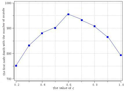
In the formula Rmin=c*Rmax, the c value determines the width of the closet ring to the base station. If the value is too large, the ring will not be easily distinguishable at the width. The c value was determined through the simulation.
Figure 4. The variation in the number of the round of the first death the c value
As shown in Figure 4, the time of the first death changed with the number of round. As the c value increased from 0.2, the number of the round of the first death increased continuously. However, when the c value surpassed 0.6, this number started to decrease. Hence, the c value was selected as 0.6.
Figure 5. The variation in network energy consumption with the growing number of rounds
Energy saving has always been the focus of routing algorithms, due to the limited energy of each sensor. As shown in Figure 5, the network energy consumption of UCRA changed less violently than that of LEACH and EEUC, with the growing number of rounds. The superior energy-efficiency of the UCRA is attributable to the following facts. In the UCRA, the network is divided into multiple unequal rings according to the distance to the base station, and control the ring width within the threshold, aiming to solve the hot-spot problem. In this way, the intra-cluster data transmission will consume fewer energy. To transmit data to the base station, each cluster head selects a cluster head satisfying d2(Si,Sj)+d2(Sj,BS)<dβ(Si,BS) as the transit sensor, thus reducing the energy consumed in inter-cluster data transmission.
Figure 6. The variation in the number of dead sensors with the growing number of rounds
In the WSN, the time of death of each sensor directly bears on the network operation. Premature death and the number of rounds between the first and last deaths (the first-last death difference) both affect the data collection and transmission across the network. It can be seen from Figure 6 that, the LEACH had the earliest first death and the largest first-last death difference; the EEUC saw early deaths of all network sensors, despite a small first-last death difference; the UCRA achieved longer survival time of sensors than the two contrastive protocols. The excellent performance of the UCRA can be explained as follows: To solve the hot-spot problem, the UCRA requires that the ring closer to the base station be narrower, such that the sensors close to the base station will not face energy depletion due to data transmission. As a result, the intra-cluster energy consumption of the UCRA is lowered. Besides, more cluster heads are elected to share the energy consumption.
Drawing on clustering routing algorithms like LEACH and EEUC, this paper puts forward the UCRA to extend the survival time of sensors and balance the energy consumption across the WSN. The UCRA firstly initializes the network and divides the monitoring area into several rings by concentric circles. Then, the cluster heads are elected based on the residual energy and local ring. In the clustering phase, each sensor joins a suitable cluster based on its local ring and the distance between the cluster head and the centerline of the ring. Before inter-cluster transmission, the neighboring cluster heads with the most residual energy in the previous ring are selected as the routing sensors. The simulation results show that the UCRA can effectively extend the survival time of network sensors and balance the energy consumption across the network.
(1) The Research on Early Warning Mechanism of Home Care for the Aged Based on Wireless Sensor Network (PXYQNJJ2016017), Pingdingshan College Youth Fund (Natural science) general project.
(2) Young backbone teacher training program of Henan colleges and universities(2019GGJS235).
[1] Barati, H., Movaghar, A., Rahmani, A.M. (2015). EACHP: Energy aware clustering hierarchy protocol for large scale wireless sensor networks. Wireless Personal Communications, 85(3): 765-789. https://doi.org/10.1007/s11277-015-2807-2
[2] Zhao, M., Kumar, A., Chong, P.H.J., Lu, R.X. (2017). A reliable and energy-efficient opportunistic routing protocol for dense lossy networks. IEEE Wireless Communications Letters, 6(1): 26-29. https://doi.org/10.1109/LWC.2016.2625279
[3] Liao, F., Zhang, W. (2017). Uneven clustering routing protocol based on minimum spanning tree. Chinese Journal of Sensors and Actuators, 30(9): 1412-1416. http://dx.chinadoi.cn/10.3969/j.issn.1004-1699.2017.09.019
[4] Pan, J.Q., Feng, Y.Z. (2018). Improved LEACH clustering routing algorithm of sensor network. Journal of Jilin University (Science Edition), 56(6): 1476-1482. http://xuebao.jlu.edu.cn/lxb/CN/Y2018/V56/I6/1476
[5] Hu, F.S., Xiao, Q. (2014). Multi-hop routing algorithm of energy-balancing based on LEACH. Journal of Chinese Computer Systems, 35(1): 70-73. http://xwxt.sict.ac.cn/EN/Y2014/V35/I1/70
[6] Arumugam, G.S., Ponnuchamy, T. (2015). EE-LEACH: Development of energy-efficient LEACH protocol for data gathering in WSN. EURASIP Journal on Wireless Communications and Networking, (1): 76. https://doi.org/10.1186/s13638-015-0306-5
[7] Liu, W., Du, J.H., Jia, S.L., Pu, J.H. (2019). Energy efficient clustering routing protocol for wireless sensor networks. Journal of Beijing University of Aeronautics and Astronautics, 45(1): 50-56. https://doi.org/10.13700/j.bh.1001-5965.2018.0251
[8] Khediri, S.E.L., Nasri, N., Wei, A., Kachouri, A. (2014). A new approach for clustering in wireless sensors networks based on LEACH. Procedia Computer Science, 32: 1180-1185. https://doi.org/10.1016/j.procs.2014.05.551
[9] Taheri, H., Neamatollahi, P., Younis, O.M., Naghibzadeh, S., Yaghmaee, M.A. (2012). An energy-aware distributed clustering protocol in wireless sensor networks using fuzzy logic. Ad Hoc Networks, 10(7): 1469-1481. https://doi.org/10.1016/j.adhoc.2012.04.004
[10] Heinzelman, W.B., Chandrakasan, A.P., Balakrishnan H. (2002). An application- specific protocol architecture for wireless microsensor networks. IEEE Transactions on Wireless Communications, 1(4): 660-670. https://doi.org/10.1109/TWC.2002.804190
[11] Ding, L., Zhou, G.T., Morgan, D.R., Ma, Z.X., Kenney, J.S., Kim, J., Giardina, C.R. (2004). A robust digital baseband predistorter constructed using memory polynomials. IEEE Transactions on Communications, 52(1): 159-165. https://doi.org/10.1109/TCOMM.2003.822188
[12] Younis, O., Fahmy, S. (2004). HEED: A hybrid, energy-efficient, distributed clustering approach for ad hoc sensor networks. IEEE Transactions on Mobile Computing, 3(4): 366-379. https://doi.org/10.1109/TMC.2004.41.doi:10.1109/TMC.2004.41
[13] Soro, S., Heinzelman, W.B. (2005). Prolonging the lifetime of wireless sensor networks via unequal clustering. IEEE International Parallel & Distributed Processing Symposium, Denver, CO, USA. https://doi.org/10.1109/IPDPS.2005.365
[14] Li, C.F., Chen, G.H., Ye, M., Wu, J. (2007). An uneven cluster-based routing protocol for wireless sensor networks. Chinese Journal of Computers, 30(1): 27-36. http://dx.chinadoi.cn/10.3321/j.issn:0254-4164.2007.01.004
[15] Gibbson, J.D. (1996). The mobile communications handbook. Springer.
[16] Li, J., Li, Z.Y., Wang, R.C. (2009). A coverage-preserving node scheduling scheme based on energy prediction in wireless sensor networks. Journal of Nanjing University of Posts and Telecommunications (Natural Science Edition), 29(2): 16-21. http://dx.chinadoi.cn/10.3969/j.issn.1673-5439.2009.02.004