Wisam Hameed Hanoon | Nasri S.M. Namer | Sami Ali Nama*
© 2022 IIETA. This article is published by IIETA and is licensed under the CC BY 4.0 license (http://creativecommons.org/licenses/by/4.0/).
OPEN ACCESS
3D printing is one of the contemporary technologies that can be used effectively to produce forming tools. Punch- rotary rocker arrangements were printed from Polyethylene Terephthalate Glycol (PETG) filament, and were used to perform bending process for sheets of Titanium Grade2 (TiG2). Four variables, each of which has four levels were investigated numerically by means of DEFORM 2D software to find out their effect on springback angle. Wall thickness (4, 6, 8mm, and solid 100% infill), rocker inner radius (1, 1.5, 2, 2.5mm), punch radius (1, 1.5, 2, 2.5mm), and plate thickness (0.5, 0.8, 1, 1.25mm). experimental work was also conducted to verify the numerical work. The results showed that increasing wall thickness decreases the resulting springback angle, and the deviation of spring back angle between the solid rocker and that of (6 and 8mm wall thickness) was 1.14% and 1.10% respectively. Also, it was found that increasing rocker inner radius, punch radius, and plate thickness decreases the spring back. For different rocker bending angle, “hook” phenomenon plays a major role in the resulting spring back value.
3D printing, bending rocker, deform 2D, spring back, TiG2
Bending of sheet metal is a common and important process in industry. The bending process accompanies the phenomenon of spring back, which occurs as a result of the metal flexible recovery after releasing the applied load [1]. The occurrence of a springback depends on several factors including bending tool shape, material properties, metal orientation, metal thickness, bending mold radius, punch radius, and bending speed. Rotary rocker bending is one of sheet bending operations, it can be in the form of different shapes [2, 3], and the final bend can vary according to the required angle [4, 5]. One of the main parameters that affects the spring back is the plate thickness, it was found that when the plate thickness increases, the springback decreases [6, 7]. The bending process is subjected to the stress-strain behavior of the sheet metal under tensile stress loading, and (Bauschinger effect) in changing the stress properties of the material as a result of the microscopic stress distribution of the material, an increase in the yield strength to tensile occurs at the expense of the compressive strength [8].
3D printing is a modern technology in the modeling industry and can be used to make simple and complex shapes. One of the important characteristics of 3D printing is its ability to control the density of the material inside the printed part (internal filling ratio), and thus control the stiffness of the printed product and improve its mechanical properties. Researchers are trying recently to use plastic tools made with 3D printing technology to form sheet metal to the required shapes. There is a tendency to use 3D-printed tools to produce small, on demand quantities instead of metallic bending tools to bend sheet metals. This is because the printed tools reduce the cost and manufacturing time of tools. The bending process depends on the quality of the flint and its mechanical properties, some of which resist the change in dimensions and are not affected by the force used in the bending process as a result of those properties. If the effective pressure does not exceed the elastic limit of the 3D printed plastic tool, it can be effectively used in sheet metal forming process [9-12]. Depending on the mechanical properties, various filament materials can be used for 3D printing, these includes PETG (polyethylene terephthalate glycol), PLA (Polylactic acid), ABS (Acrylonitrile Butadiene Styrene), PET (Polyethylene Terephthalate), to print required bending tool [13-16]. This work aims to investigate the possibility of using a mold that is printed from a PETG filament to perform the L-shaped rotary rocker bending process for titanium sheets and compare it with a metal mold in manufacturing and cost.
PETG Wire filament was used with the 3D printing machine, the wire was heated and extruded layer by layer to produce the different mold parts.
2.1 Materials
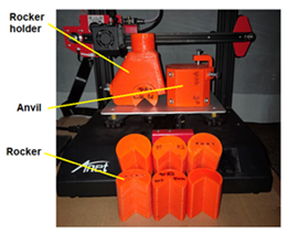
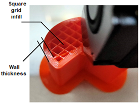
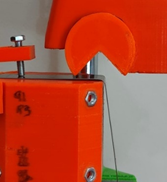
To investigate the effect of bending variables on springback, sheets of TiG2 with different thicknesses (0.5-1mm) were used. Six anvil-rotary rocker arrangements were manufactured from 1.75mm diameter PETG wire filament as shown in Figure (1-a). Rockers were made with different bending angles (89, 90, and 91 degrees), for each angle two rockers inside radii (Rr = 1 and 2mm) were used. Six anvils were also printed with the same rocker bending angles. For each angle, two anvil nose radii were used (Ra = 1 and 2mm). The rocker dimensions were adopted according to Dayton Lamina company [17]. Two strategies were adopted for the parts inside filling, (50% square grid infill for the rotary rockers, and 30% square grid infill for the other parts) as shown in Figure (1-b). The other printing parameters were (wall thickness 6mm, nozzle diameter 0.4mm, layer height 0.15mm, and heating temperature 245℃).
(a) Printed parts
(b) Printing infill
Figure 1. Anvil-rocker arrangement
The mechanical properties of PETG were (Tensile Yield Stress = 50 MPa, flexural modulus = 1880 MPa, impact strength = 11 kJ/m2) [18] and for TiG2 are listed in Table 1.
Table 1. TiG2 Mechanical properties [19]
|
Yield strength (MPa) |
Tensile strength (MPa) |
Young modulus (GPa) |
Poisson's ratio |
Flow stress |
|
219.554 |
329.331 |
113.5 |
0.37 |
σ =700.64 ε0.4 |
2.2 Bending process
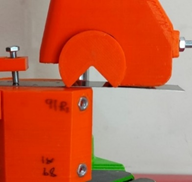
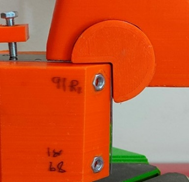
In rotary bending, a special anvil-rotary rocker arrangement is used to bend the sheet of metal. The rotary rocker is a cylinder having a V opening along its length. The rocket is seated and can rotate inside the rocker holder. The sheet metal is positioned on the anvil by means of another holder. The bending process can be performed by pushing the rocker downwards. When the rocker become in contact with the sheet metal it starts rotating around the anvil tip and bending the sheet as shown in Figure 2.
(a) Plate fixing
(b) Bending
(c) Finish bending
Figure 2. Rotary bending process
The final spring back angle of the TiG2 sheets was measured, its variation with the different bending parameters will be discussed below.
3.1 Effect of wall thickness.
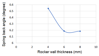
Four rotary rockers where printed, three of them have (4, 6, and 8mm) wall thickness and (50% square grid infill), while the fourth one was solid (100% infill). These arrangements were used to bend TiG2 sheets of 1mm thickness, the other parameters were (rocker angle 90°, rocker inside radius 2mm, and anvil radius 2mm). the resulting spring back angle for the solid rocker was 6.1167°, while the springback angle for the other rockers is shown in Figure 3.
It can be noted that the resulting springback angle decreases with increasing the wall thickness, this can be attributed to the increase in the rocker rigidity and decrease in its tendency for deformation. The springback angle for 6mm wall thickness was 6.187° while for 8mm wall thickness it was 6.180°, therefore the deviation of spring back angle between the solid rocker and that of 6 and 8mm wall thickness was 1.14% and 1.10% respectively. Also, it can be noted that there is a slight difference in springback angle for 6 and 8mm wall thickness therefore the 6mm wall thickness was adopted when printing the different parts.
Figure 3. Spring back angle variation at different rockers wall thickness
3.2 Effect of rocker inner radius
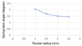
Changing the rocker inner radius and its effect on spring back angle was investigated numerically and experimentally, the numerical results are shown in Figure 4. It can be noted that when the rocker inner radius increases, the springback angle decreases. Increasing the rocker radius decreases the stresses developed in the outer fiber of the TiG2 plate and this in turn results in decreasing the residual stresses after unloading the plate which decreases the resulting spring back angle. The experimental results showed the same behavior, for 1mm and 2mm rocker radius the spring back angle was 8.889° and 8.741° respectively.
Figure 4. Spring back angle variation with rockers radius
(Anvil radius1mm, plate thickness 1mm, angle 89°)
3.3 Effect of anvil radius
Again, the effect of changing the anvil radius on springback angle was studied numerically and experimentally, the results are shown in Figure 5. Increasing the anvil radius decreases the resulting springback angle. The inner surface of the plate is in contact with the punch radius. Increasing the punch radius results in less stress in the lower portion of the plate and this decreases the amount of the springback angle. For 1and 2mm anvil radius the experimental results for spring back angle were 8.889° and 8.349° respectively.
Figure 5. Variation of Spring back angle with anvil radius
(Rocker radius1mm, plate thickness 1mm, and angle 89°)
3.4 Effect of plate thickness
Figure 6 shows the numerical results of springback angle for different plate thickness. It can be noted that with increasing the plate thickness the resulting spring back angle decreases. The experimental results showed an opposite manner, they were (8.175° and 9.889° for 0.5 and 1mm respectively). Increasing the plate thickness increases its rigidity and this may increase the deformation in the rocker which increases in turn the resulting spring back angle.
Figure 6. Spring back angle variation with plate thickness
(Rocker radius1mm, anvil radius 1mm, angle 89°)
3.5 Effect of Rocker angle
The experimental and numerical results of springback angle value at different bending angles are listed in Table 2, it can be noted that there is a discrepancy in the springback angle values. In the case of equal rocker and anvil radius (1mm), an increase in the bending angle leads to a decrease in the springback angle for both 0.5 and 1mm plate thickness. When the rocker and anvil radius equals (2mm), increasing the bending angle increases the springback angle. In the case of unequal rocker and anvil radius, the plate thickness effects the springback behavior. For plate thickness 0.5mm, increasing the bending angle leads to an increase in the springback angle to a maximum value and then it decreases. For plate thickness 1mm, a reverse behavior was noted in the springback angle. This discrepancy in the springback angle values can be related to the “hook” phenomenon as shown in Figure 7. The effect of this phenomenon decreased as the bending angle increase.
Table 2. Experimental and numerical springback results at different parameters
|
No. |
Plate thickness (mm) |
Rocker radius (mm) |
Anvil radius (mm) |
Bending angle (Experimental) |
Bending angle (Simulation) |
||||
|
89⁰ |
90⁰ |
91⁰ |
89⁰ |
90⁰ |
91⁰ |
||||
|
1 |
0.5 |
1 |
1 |
8.1749 |
7.8937 |
6.4079 |
4.3576 |
3.7028 |
2.4219 |
|
2 |
0.5 |
1 |
2 |
8.2179 |
9.5421 |
8.6094 |
4.3113 |
6.4563 |
5.0655 |
|
3 |
0.5 |
2 |
1 |
6.3609 |
8.5363 |
6.7807 |
4.2385 |
5.1084 |
4.5544 |
|
4 |
0.5 |
2 |
2 |
6.1199 |
8.8020 |
9.8884 |
2.4326 |
3.3942 |
5.1671 |
|
5 |
1.0 |
1 |
1 |
8.8886 |
6.9464 |
6.7987 |
2.0602 |
1.3204 |
1.1443 |
|
6 |
1.0 |
1 |
2 |
8.3488 |
8.0798 |
8.7614 |
1.8096 |
1.7590 |
2.0698 |
|
7 |
1.0 |
2 |
1 |
8.7409 |
6.0941 |
7.4547 |
2.9044 |
1.3662 |
2.4384 |
|
8 |
1.0 |
2 |
2 |
6.1474 |
6.5423 |
8.1470 |
1.5096 |
1.8833 |
2.1710 |
Figure 7. Hook phenomenon in rotary bending
By using the experimental and numerical data obtained for the different printing parameters and with the help of the DataFit [20] software, the relation between the spring back angle and the printing variables can be defined by the following empirical equation:
Spring back angle = (a*t)+(b*Rr)+(c*Ra)+(d*α)
where:
t = plate thickness (mm)
Rr = Rocker radius (mm)
Ra = Anvil radius (mm)
α = Bending angle (degree)
a, b, c, and d are constants as listed in Table 3.
Table 3. Values for the empirical constants
|
constant |
Experimental |
Numerical |
|
a |
-0.7329 |
-4.7974 |
|
b |
-0.5890 |
5.6639 |
|
c |
0.6763 |
0.2002 |
|
d |
9.0897 |
6.9795 |
3.6 Economic considerations
There are many economic advantages that can be achieved with 3D printing technique. 3D printed rotary bending parts are lighter than that made of steel, besides it is possible to control the internal filling ratio of printed parts. The printer and PETG filament are cheap in comparison with same metallic parts (The price of the printer with 2 kilos PETG filament is \$200, while the cost for the same metallic parts is around \$2000). Technically, manufacturing metallic rotary banding parts need a highly qualified worker, while printed dies don’t need such worker as their manufacturing process needs experience in the field of 3D design and knowledge of printing programs. Finally, the complete printed bending parts with their accessories needs manufacturing time less than that required for the metallic parts and this again considerably reduces the overall cost.
This work investigated the effect of 3D-printed bending variables (bending angle, plate thickness, rotary rocker and anvil radii) on springback angle when bending TiG2 sheets. Numerical and experimental methods were adopted to achieve that. The following conclusions were noted:
[1] Darmawan, A.S., Anggono, A.D., Hamid, A. (2018). Die design optimization on sheet metal forming with considering the phenomenon of springback to improve product quality. MATEC Web Conf., 154: 2-5. https://doi.org/10.1051/matecconF/201815401105
[2] Livatyali, H. (2021). Experimental comparison of straight flanging and rotary die bending based on springback. Research Square, 1-21. https://doi.org/10.21203/rs.3.rs-667515/v1
[3] Dayton Lamina. Posi-Bend Rotary Benders. https://www.daytonlamina.com/pdf/205_Posi-Bend_Rotary_Bender.pdf, accessed on Jan. 3, 2022.
[4] Phanitwong, W., Thipprakmas, S. (2016). Development of anew spring-back factor for a wiping die bending process. Mater. Des., 89: 749-758. https://doi.org/10.1016/j.matdes.2015.10.031
[5] Jafari, M., Lotfi, M., Ghaseminejad, P., Roodi, M., Teimouria, R. (2015). Numerical control and optimization of springback in L-bending of magnesium alloy through FE analysis and artificial intelligence. Trans. Indian Inst. Met., 68(5): 969-979. https://doi.org/10.1007/s12666-015-0535-7
[6] Özdemİr, M. (2017). Mathematical modeling of the effect of different parameters on spring back in sheet metal formability process. American Journal of Engineering Research (AJER), 6(10): 198-205. http://www.ajer.org/papers/v6(10)/ZB0610198205.pdf.
[7] Wasif, M., Iqbal, S.A., Tufail, M., Karim, H. (2019). Experimental analysis and prediction of Springback in v-bending process of high-tensile strength steels. Trans. Indian Inst. Met., 73: 285-300. https://doi.org/10.1007/s12666-019-01843-5
[8] Gupta, T. (2019). Predicting and reducing springback in bending of an aluminum alloy and selected advanced high strength steels (AHSS). Master Thesis, the Ohio State University. https://etd.ohiolink.edu/apexprod/rws_etd/send_file/send?accession=osu1555599407775667&disposition=inline.
[9] Aksenov, L.B., Kononov, I.Y. (2019). 3D printed plastic tool for Al thin-sheet forming. IOP Conf. Ser. Earth Environ. Sci., 337(1): 012053. https://doi.org/10.1088/1755-1315/337/1/012053
[10] Lindquist, E.M., Gosnell, J.M., Khan, S.K., Byl, J.L., Zhou, W.H., Jiang, J.F., Vettukattil, J.J. (2021). 3D printing in cardiology: A review of applications and roles for advanced cardiac imaging. Ann. 3D Print. Med., 4: 100034. https://doi.org/10.1016/j.stlm.2021.100034
[11] Zelený, P., Váňa, T., Stryal, J. (2016). Application of 3D printing for specific tools. Mater. Sci. Forum, 862: 316-323. https://doi.org/10.4028/www.scientific.net/MSF.862.316
[12] Durgun, I. (2015). Sheet metal forming using FDM rapid prototype tool. Rapid Prototyp. J., 21(4): 412-422. https://doi.org/10.1108/RPJ-01-2014-0003
[13] Durgashyam, K., Indra Reddy, M., Balakrishna, A., Satyanarayana, K. (2019). Experimental investigation on mechanical properties of PETG material processed by fused deposition modeling method. Mater. Today Proc., 18(6): 2052-2059. https://doi.org/10.1016/j.matpr.2019.06.082
[14] Dev, A.D., Avala, B., Reddy, R., Arjula, S. (2018). Characterization of additive manufactured PETG and carbon fiber-PETG. Int. J. Res. Eng. Appl. Manag., 4: 2. https://doi.org/10.18231/2454-9150.2018.0139
[15] Srinivasan, R., Nirmal Kumar, K., Jenish Ibrahim, A., Anandu, K.V., Gurudhevan, R. (2020). Impact of fused deposition process parameter (infill pattern) on the strength of PETG part. Mater. Today Proc., 27(2): 1801-1805. https://doi.org/10.1016/j.matpr.2020.03.777
[16] Nouman, F.E., Nama, S.A., Mahdi, H.H. (2021). Effect of infill percentage for 3D printed dies on spring back for aluminum sheets. International Journal on Technical and Physical Problems of Engineering, 13(4): 27-32.
[17] Design and Maintenance Recommendations. www.daytonlamina.com, accessed on October 15, 2021.
[18] Filament, P.M. (1880). Technical Data Sheet for Product: PLA Filament. https://www.filament-pm.com/data/files/TDS_PLA.pdf, accessed on March 2, 2021.
[19] Jameel L.S., Namer, N.S.M., Nama, S.A. (2021). Hole-clinching joint of polymer to titanium sheets, experimental and numerical analysis. Journal of Mechanical Engineering Research and Development, 44(3): 242-250. https://jmerd.net/03-2021-242-250/
[20] DataFit, Version 9.1.32, Oakdale Engineering, 2014, http://www.curvefitting.com, accessed on February 18, 2022.