Xiaoyan Li* | Hua Li | Yufei Peng | Jikang Wang
© 2021 IIETA. This article is published by IIETA and is licensed under the CC BY 4.0 license (http://creativecommons.org/licenses/by/4.0/).
OPEN ACCESS
Large-scale long-distance grid connection of wind farms has problems such as high line losses and small transmission capacity. The use of modular multilevel flexible direct current transmission (MMC-HVDC) for power transmission is an effective solution. And the recovery of system safety and stability under fault conditions is a hot spot for research. For the problem of DC bus voltage rise caused by symmetrical faults on the grid side, the AC voltage step-down method of the wind farm side converter station (WFMMC) is used for coordinated control with the self-regulating energy-consuming circuit. The capacity required for the self-regulating dissipation resistor is reduced while ensuring that the wind farm networked MMC-HVDC system can traverse the fault stably and smoothly; And the controller for suppressing negative sequence current is designed to effectively mitigate the three-phase current imbalance caused by asymmetric faults occurring on the grid side. The active power is transferred to the grid side while protecting the switching devices from damage. Finally, the correctness and effectiveness of the proposed scheme are verified in the PSCAD/EMTDC simulation software.
wind power, MMC-HVDC, symmetric faults, asymmetric faults, fault ride-through
After coal and hydropower, wind power has become the third largest conventional power source in China. Increasing the proportion of wind power in the national power structure is of great significance to reduce carbon emissions [1]. China's "Three Norths" region is rich in wind energy resources, but it is far from the southeast coast where the electricity load is high. The phenomenon of wind energy abandonment is serious here. The characteristics of the reverse distribution determine the need for long-distance and large-capacity transmission of wind power. MMC-HVDC was proposed by Rainer Marquaidt and Anton Lesnicar in 2002. MMC converter station has many advantages such as strong structural expandability, low device switching frequency, and low harmonic distortion rate on the AC side. It is now widely used in wind farms as a passive network to the grid [2].
Based on the fault ride-through capability of wind farms via MMC-HVDC networking system is a hot topic of current research [3]. The literature [4] introduces a flexible energy drainage resistance scheme for fault ride-through of wind farms via MMC-HVDC networking system. It gives the energy drain resistance calculation criteria and designs a flexible energy drain resistance control strategy applicable to different wind power operating conditions and fault depths. The literature [5] introduces a second-order complex filter to extract the positive and negative sequence components of the grid voltage under asymmetric faults. It derives the negative sequence components based on the voltage compensation principle to improve the inner-loop current controller and designs a two-fold zero-sequence compensator to achieve stable DC voltage.
To solve the fault ride-through problem of wind farms connected to the grid via DC transmission, this paper takes MMC-HVDC networked large-scale doubly-fed (DFIG) wind farms as the research object to analyze the system safety and stability problems when different types of faults occur on the AC grid side. Different control strategies are adopted to enhance the fault ride-through capability of the system, and the simulation analysis is carried out by PSCAD/EMTDC simulation software.
Taking the Sheyang offshore wind power flexible DC transmission demonstration project in Jiangsu as a reference, the structure diagram of the DFIG wind farm based MMC-HVDC networking system is designed as shown in Figure 1. The power generated by the two wind farms is gathered to the bus via their respective step-up transformers, forming a collector system and then sent to the WFMMC via the T3 converter transformer, transmitted to the receiving converter station (GSMMC) via the DC cable, and then the energy is transferred to the grid via the T4 converter transformer.
The WFMMC needs to provide synchronous power to the wind farm, otherwise the wind farm cannot operate stably. The controller uses AC voltage and frequency control to provide stable amplitude and frequency for the voltage of the wind farm collector system. The GSMMC uses DC voltage and reactive power control to maintain stable DC bus voltage and deliver more active power [6]. Based on the simulation model built using the above control strategy in the converter station, the fault characteristics of the AC grid side are analyzed and the corresponding control strategy is used in order to achieve fault ride-through.
Figure 1. Wind farm based on MMC-HVDC networking system structure
The power delivered by the system-side converter station decreases due to a severe drop in the grid-side three-phase AC voltage. Due to the DC transmission with isolation fault capability [7], the wind farm side converter station feeds in the active power unchanged. The power delivered by the converter stations at both ends is unbalanced and the excess energy charges the capacitors causing an increase in the DC voltage. The system fault ride-through under severe fault conditions cannot be achieved solely by the regulating action of the converter station itself. Referring to the BorWin1, DolWin1 and DolWin2 projects, HelWin1/2 and SylWin1 projects [8, 9], adaptive energy dissipation resistors are introduced in parallel to the DC bus near the GSMMC to dissipate the excess energy in the form of load to restore the DC voltage stability.
3.1 Self-regulating energy-consuming resistor and its control method
The self-regulating energy consumption resistor proposed in reference [10] uses a conventional centralized energy consumption resistor Rchopper dispersed into a number of identical Ri sub-modules (SM) formed in parallel. Each individual Ri has an independent control switch to control the input and removal. Only the unloading circuit is used to dissipate the excess energy. Neglecting converter and line losses, the resistive element parameters are designed to balance out the power difference between the two ends of the MMC-HVDC system under the most severe fault. Assume that during a fault, the DC voltage rises to the maximum value Udcmax and each sub-module consumes the rated power Pi for a total of n sub-modules:
${{P}_{i}}=\frac{U_{_{dc\max }}^{2}}{{{R}_{i}}}$ (1)
When all n sub-modules are switched to consume the power difference between the two ends of the wind farm-side converter and the system-side converter, the rated active power ∆Pdc of the DC system is:
$\Delta {{P}_{dc}}=n{{P}_{i}}$ (2)
Then the resistance Ri of each sub-module is:
${{R}_{i}}=n\frac{U_{_{dc\max }}^{2}}{\Delta {{P}_{dc}}}$ (3)
The unloading circuit calculates the current number of submodules to be put in nsm (1 ≤ nsm ≤ n) according to the difference in power difference between the two converter stations due to the severity of the fault.
${{n}_{sm}}=n[({{P}_{in}}-{{P}_{out}})/\Delta {{P}_{dc}}]$ (4)
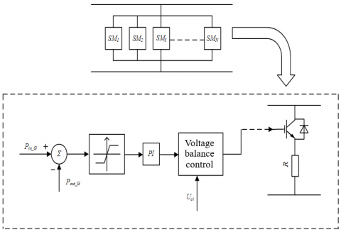
Figure 2. Self-regulating energy-consuming resistor control diagram
Pin indicates the DC-side input power delivered by the wind farm to the sending converter station, and Pout is its AC-side output power. The self-regulating resistor circuit uses a control block diagram as in Figure 2. It can calculate the current power difference to be dissipated based on the depth of the fault drop. After PI link output nsm sub-modules, drawing on the sub-module capacitor voltage balance control based on the voltage balance control of the resistor voltage sampling value UCi (1 ≤ i ≤ n) to generate a pulse signal. The trigger signal is applied to the IGBT tube to get the corresponding throw-off signal. Compared with the conventional unloading circuit, the economy is improved by the fact that the self-regulating resistor circuit does not require the installation of a capacity matching the output power of the wind farm for fault situations where only a small power difference is consumed. And along with the increase in the number of sub-modules, the heat dissipation of the work is improved and the fault ride-through control effect will be further enhanced.
3.2 Fault ride-through coordinated control method
The frequency boost and voltage reduction methods are used as a typical means of fault ride-through for wind farms via flexible and straight systems. The literature [4] points out that variable-speed, constant-frequency doubly-fed wind turbines are insensitive to changes in AC grid frequency. When using the step-up method, it is necessary to consider not only whether the power electronics can withstand large frequency changes, but also the slow recovery of both the rotational speed and active power of the wind turbine after fault removal. Therefore, in this paper, the step-down method is combined with the self-regulating energy dissipation resistor for coordinated control. The specific method of the buck method is shown below.
${{V}_{WF\_ref}}=\left\{ \begin{matrix} {{V}_{ac\_nom}} \,\,\,\,\,\,\,\,\,\, \text{ }{{U}_{dc}}{{U}_{dc\_thr}}\text{ } \\ {{V}_{ac\_nom}}-{{k}_{v}}({{U}_{dc}}-{{U}_{dc\_thr}})\text{ }{{U}_{dc\_thr}}<{{U}_{dc}}<{{U}_{dc\_\lim }} \\ {{V}_{ac\_\min \,\,\,\,\,\,\,\,\,\, \text{ }}}\text{ }{{U}_{dc}}{{U}_{dc\_\lim }} \\ \end{matrix} \right.$ (5)
where, $k_{v}=\frac{V_{a c_{-}} \mathrm{nom}-U_{a c_{-}} \mathrm{min}}{U d c_{-} t h r_{d c_{-}} \mathrm{lim}}$, the value determines the rate of AC voltage drop.
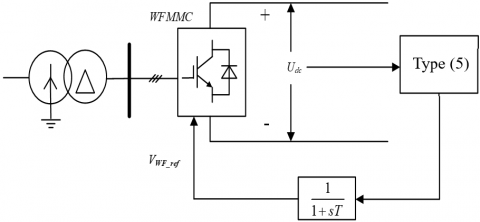
Figure 3. WFMMC buck method control strategy
The upper limit of DC voltage Udc_lim is taken as 1.1pu, Vac_nom is the nominal line voltage of the wind farm side converter station with a minimum value of 1pu, and the start-up threshold Udc_thr of the step-down method is set to 1.05pu. The voltage reduction method is equivalent to the manual setting of short-circuit fault. According to the standard of our turbine traversal, the turbine needs to be able to traverse a voltage dip of minimum 0.2pu. The literature [11] analyzed the step-down method for Uac_min taking values of 0.2pu, 0.5pu, and 0.8pu. The transient overcurrent shocks that are very likely to result from too low a choice of the buck limit value affect the normal operation of the doubly-fed asynchronous generator and even lead to the collapse of the DC transmission system. In this paper, the value of Uac_min is taken as 0.6pu. Since the DC voltage fluctuates greatly during fault ride-through, the AC voltage control command calculated using the buck method is first passed through the first-order inertia link and then passed to the MMC controller. A schematic diagram of the buck method control strategy is shown in Figure 3.
The initial stage of the fault is to first consider reducing the wind farm power output at the WFMMC control voltage limit. No changes are made internally to the wind turbine to initially reduce the wind field side output power; Secondly, the sub-modules of the self-regulating energy dissipation resistor circuit are redesigned based on Eqns. (1)-(4) according to the actual output power of the wind field side after the voltage reduction.
If an asymmetric fault occurs at point F on the AC grid side, there is no circuit for the zero sequence component to flow after the Yn/∆ connected T4 converter transformer, only positive and negative sequence components flow into the converter station. If a large negative sequence current is generated in the system, the flow into the converter station will cause the destruction of the converter equipment and lead to system shutdown. Due to the isolation of the DC network, the individual electrical quantities of the WFMMC are almost unaffected. It is only necessary to design positive and negative sequence controllers on the GSMMC side for the purpose of suppressing negative sequence currents to maintain safe and stable operation of the system.
4.1 Mathematical modeling of MMC-HVDC under asymmetric faults
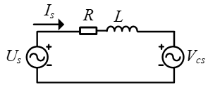
Reference [12], the MMC converter station is simplified to the equivalent circuit of Figure 4:
Figure 4. MMC AC side equivalent circuit diagram
The relationship in Figure 4 is given by the KVL law:
${{U}_{\text{s}}}=R{{I}_{s}}+L\frac{d{{I}_{s}}}{dt}+{{V}_{s}}$ (6)
Us is the grid voltage, Is is the AC current flowing into the MMC side, R is the AC side equivalent resistance, L is the AC side equivalent inductance, and Vs is the MMC AC side voltage.
The voltage and current components in the three-phase stationary coordinate system are coupled in controlling the active and reactive power, which increases the difficulty of the controller design. To achieve decoupled control of power, the control strategy adopted is established in the dq rotating coordinate system. Based on the expression of Eq. (6), the mathematical model of the positive and negative sequence components of the MMC commutation system under the dq axis when an asymmetric fault occurs on the grid side is.
$\left\{ \begin{matrix} u_{_{cd}}^{+}=-Ri_{sd}^{+}-L\frac{di_{sd}^{+}}{dt}+wLi_{sq}^{+}+u_{sd}^{+} \\ u_{_{cq}}^{+}=-Ri_{sd}^{+}-L\frac{di_{sd}^{+}}{dt}-wLi_{sd}^{+}+u_{_{sq}}^{+} \\ \end{matrix} \right.$ (7)
$\left\{ \begin{matrix} u_{_{cd}}^{-}=-Ri_{sd}^{-}-L\frac{di_{sd}^{-}}{dt}-wLi_{sq}^{-}+u_{sd}^{-} \\ u_{_{cq}}^{-}=-Ri_{sd}^{-}-L\frac{di_{sd}^{-}}{dt}+wLi_{sd}^{-}+u_{_{sq}}^{-} \\ \end{matrix} \right.$ (8)
$u_{s d}^{+}, u_{s q}^{+}, u_{s d}^{-}$, and $u_{s q}^{-}$ are the d- and q-axis components of the positive and negative sequence voltages on the AC side of the grid, respectively; $u_{c d}^{+}$, and $u_{c q}^{+}$, and $u_{c d}^{-}$, and $u_{c q}^{-}$ are the d- and q-axis components of the positive and negative sequence voltages on the valve side of GSMMC converter station, respectively. $i_{s d}^{+}$, and $i_{s q}^{+}$, and $i_{s d}^{-}$, and $i_{s q}^{-}$ are the d- and q-axis components of the positive and negative sequence currents flowing into the valve side of the GSMMC converter station, respectively. ω is the fundamental angular frequency.
4.2 Study of control strategies
The GSMMC uses direct current control based on a dual-loop structure. The dual-loop structure consists of an inner and outer-loop controller. The outer-loop controller has fixed DC voltage/reactive power control and the inner-loop controller has current control.
4.2.1 Outer loop control strategy
1) Constant DC voltage control
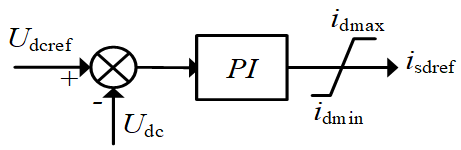
The use of constant DC voltage control is beneficial to DC bus voltage stability and active power transmission. When Udcref is given, the reference value of d-axis active current isdref is obtained by PI regulator.
${{i}_{\text{sdref}}}=\text{(}{{K}_{\text{p1}}}\text{+}\frac{{{K}_{q1}}}{s}\text{)(}{{U}_{\text{dcref}}}-{{U}_{\text{dc}}}\text{)}$ (9)
The DC voltage controller obtained according to Eq. (9) is (see Figure 5):
Figure 5. DC voltage controller
2) Constant reactive power control
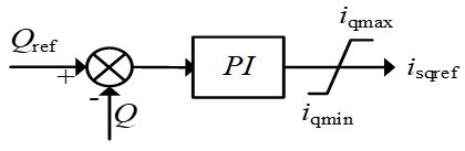
The use of constant reactive power control is beneficial to the system unit power factor operation, when Qref is given, the reference value isqref of the q-axis reactive current is obtained by the PI regulator.
${{i}_{\text{sqref}}}=\text{(}{{K}_{\text{p2}}}\text{+}\frac{{{K}_{q2}}}{s}\text{)(}{{Q}_{\text{ref}}}-Q\text{)}$ (10)
According to Eq. (10) the reactive power controller is obtained as (see Figure 6):
Figure 6. Reactive power controller
4.2.2 Inner-loop control strategy
The inner-loop controller receives the current reference value provided by the outer-loop controller and makes the inner-loop current track the reference value quickly and without static difference after PI adjustment, and the final obtained dq-axis voltage component becomes the reference wave of MMC AC voltage after 2r/3s change.
The MMC positive sequence mathematical model obtained from Eq. (7) shows that the existence of the coupling terms ωLisq and ωLisd cannot directly control Ucd and Ucq through the d- and q- axis currents for the purpose, which is not conducive to the independent control of the active and reactive power exchanged between the AC system and the converter station and needs to be decoupled.
Define $u_{d}^{+}, u_{q}^{+}$ as:
$\left\{ \begin{align} & u_{d}^{\text{+}}=L\frac{di_{\text{d}}^{+}}{dt}+Ri_{d}^{+}=-({{K}_{p1}}+\frac{{{K}_{i1}}}{s})(i_{_{dref}}^{+}-i_{_{d}}^{+}) \\ & u_{q}^{+}=L\frac{di_{q}^{+}}{dt}+Ri_{q}^{+}=-({{K}_{p2}}+\frac{{{K}_{i2}}}{s})(i_{_{qref}}^{+}-i_{_{q}}^{+}) \\ \end{align} \right.$ (11)
Then Eq. (7) can be solved as follows:
$\left\{ \begin{matrix} u_{_{cd}}^{+}=u_{d}^{+}+wLi_{q}^{+}+u_{sd}^{+} \\ u_{_{cq}}^{+}=u_{q}^{+}-wLi_{d}^{+}+u_{_{sq}}^{+} \\ \end{matrix} \right.$ (12)
The two first-order models shown in Eq. (11) form a separate current loop via the PI regulator, with the feedforward components $u_{s d}^{+}$, and $u_{s q}^{+}$ compensate off the coupling terms ωLisd, ωLisq, respectively, to ensure that the positive sequence current controller achieves decoupling control and also improves the dynamic response speed of the system. On the basis of Eq. (8), the introduction of $u_{d}^{-}$, the $u_{q}^{-}$ Eq. (13) yields the expression of the negative sequence current controller of Eq. (14) as follows:
$\left\{ \begin{align} & u_{d}^{-}=L\frac{di_{\text{d}}^{-}}{dt}+Ri_{d}^{-}=-({{K}_{p3}}+\frac{{{K}_{i3}}}{s})(i_{_{dref}}^{-}-i_{_{d}}^{-}) \\ & u_{q}^{-}=L\frac{di_{q}^{-}}{dt}+Ri_{q}^{-}=-({{K}_{p4}}+\frac{{{K}_{i4}}}{s})(i_{_{qref}}^{-}-i_{_{q}}^{-}) \\ \end{align} \right.$ (13)
$\left\{ \begin{matrix} u_{_{cd}}^{-}=u_{d}^{-}-wLi_{q}^{-}+u_{sd}^{-} \\ u_{_{cq}}^{-}=u_{q}^{-}+wLi_{d}^{-}+u_{_{sq}}^{-} \\ \end{matrix} \right.$ (14)
According to Eqns. (12) and (14), build the double sequence controller of MMC converter station as shown in Figure 7. The reference value of $i_{d r e f}^{-}$, the $i_{\text {qref }}^{-}$ is set to 0, to achieve the purpose of suppressing the negative sequence current. Meanwhile, due to the voltage dip of the grid, the active power imbalance at both ends of the converter station causes the DC bus voltage to rise, and the reference value of the power limiter current is increased in order to transmit the active power on the GSMMC side as much as possible to alleviate the power surplus problem on the DC grid. Namely.
${{i}_{\lim it}}=\sqrt{{{\text{(}{{i}_{dref\_\max }}\text{)}}^{2}}+{{\text{(}{{i}_{qref\_\max }}\text{)}}^{2}}}$ (15)
$i_{d r e f_{-} \max }$ is the reference maximum value of active current, and $i_{\text {qref_max }}$ is the reactive current reference maximum, and $i_{\text {limit }}$ is the limiter limit, depending on the maximum current allowed to pass through the IGBT tube, refer to literature [6], and set $i_{l i m i t}$ to 1.5 times the rated current.
Figure 7. Dual sequence controller
5.1 Simulation parameters
In order to verify the effectiveness of the proposed control strategy, a model based on MMC-HVDC wind farm networking is built in the PSCAD/EMTDC simulation environment. The wind speed is set to 10m/s and the rated transmission power of the wind farm is 1000MW. The relevant parameters of MMC-HVDC are shown in Table 1 below. The grid voltage drops 0.2pu at 3s and the fault is removed at 3.625s.
Table 1. MMC-HVDC system parameters
|
Parameter |
Value |
|
MMC converter rated capacity / MVA |
1000 |
|
rated direct voltage / kV |
500 |
|
Maximum DC voltage / pu |
1.1 |
|
AC voltage rating / kV |
500 |
|
SM number per arm |
100 |
|
SM capacitance/ uF |
6800 |
|
SM capacitance voltage/ kV |
5 |
|
Arm inductance / mH |
30 |
|
GSMMC control strategy |
Udc, Q |
|
WFMMC Control Strategy |
Uac, f |
5.2 Grid symmetrical faults
5.2.1 Single fault ride-through control strategy
(a) Power consumed by a single unloading resistor
(b) Power transmitted by the converter station
(c) DC line voltage
Figure 8. Simulation diagram of the system with unloading resistor
The simulation results using only the adaptive dissipation resistor are shown in Figure 8. The unloading circuit is blocked before the fault and the system operates stably. The grid-side voltage drops to 0.2pu at 3s, the GSMMC active power is reduced, and the WFMMC transmission power is almost unaffected. All the power difference on the DC line is dissipated by the unload circuit. The single unloading resistor consumes active power around 94MW. The DC voltage Udc_pu is stable below 1.05pu. At the end of the 3.625s fault, the switching device shutdown caused a transient spike in the dc bus voltage, after a short recovery the submodule capacitor discharges making the power delivered by the GSMMC greater than the power delivered by the WFMMC, causing a slight drop in the dc voltage, followed by a return to the pre-fault operating state of the system.
5.2.2 Fault ride-through coordination control strategy
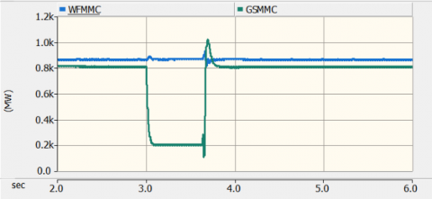
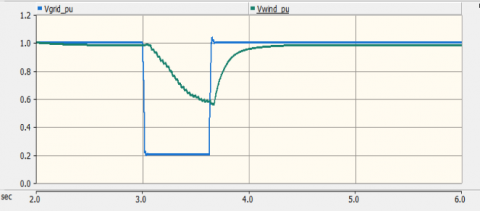
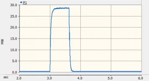
The simulation waveform obtained using the fault ride-through coordinated control strategy is shown in Figure 9. The post-fault voltage reduction method starts first, controlling the wind farm side converter station parallel network voltage Vwind_pu at 0.6pu, and the transmitted power is reduced to a minimum near 400MW, and the excess energy is started to be consumed by the adaptive dissipation resistor. From Figures (c) and (d), it can be seen that the single unloading resistor consumes less energy than the single scheme, dissipates less power, and the DC voltage is smoother than that obtained from the single scheme, verifying the effectiveness of this coordinated control scheme.
(a) Wind farm parallel network voltage
(b) DC system transmission power
(c) Power consumed by a single unloading resistor
(d) DC line voltage
Figure 9. Simulation diagram of the system with coordinated control strategy
5.3 Grid asymmetry fault
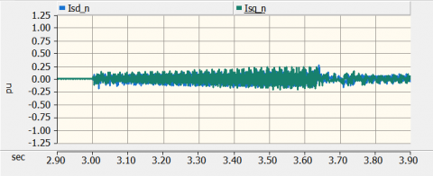
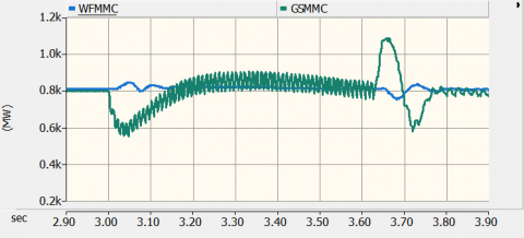
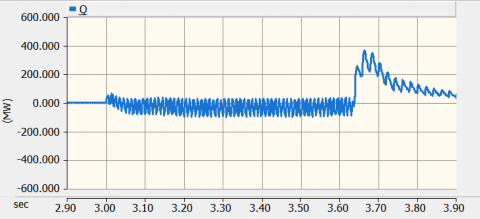
After adding the positive and negative sequence control strategy for the purpose of suppressing the negative sequence current during the fault, the negative sequence current is suppressed near 0 and the three-phase current on the AC side of the GSMMC is restored to balance. From Figure 10 (c) and (e), it can be seen that after increasing the limiting value of the power limiter, the system automatically adjusts the active current to increase the active power transmitted on the grid side, which basically returns to the transmission level before the fault and maintains the DC voltage stability. From Figure 10 (c), (d) and (e), it can be seen that the active power, reactive power and DC voltage still have diabatic fluctuations due to the presence of negative sequence voltage. And at the moment of fault occurrence and fault disappearance, each electrical quantity has certain fluctuation and impact. Under the regulating effect of the controller, the system gradually restored the stability.
a) AC side negative sequence current dq component
b) GSMMC converter station AC side current
c) Active power transmitted by the converter station
d) The reactive power Qs output to the AC system
e) DC voltage Udc
Figure 10. Simulation diagram of the system with coordinated control strategy
It is a prerequisite for the stable operation of the entire networked system to achieve fault ride-through of modular multilevel converters in case of different types of faults on the grid side. In this paper, theoretical analysis is done for the occurrence of three-phase short circuit and single-phase ground fault on the grid side, and corresponding control strategies are proposed, with the following main conclusions. (1) The adaptive energy dissipation resistor and the buck method are used to coordinate the control strategy for the symmetrical fault situation occurring on the AC grid side. The system obtains a smooth fault ride-through effect during the fault, and the capacity of the energy dissipation resistor is reduced, which helps to reduce the cost. 2) For the case of asymmetric faults occurring on the AC grid, the control strategy of suppressing negative sequence currents and increasing the active power transfer by raising the current limit value at the GSMMC converter station significantly improves the fault ride-through capability of the system.
[1] Wang, Q. (2021). 2020-2060 China' s wind power installed capacity and its CO2 emission reduction forecast. Ecological Economy, 37(7): 13-21.
[2] Zhao, J., Zhao, C.Y., Sun, Y.Y. (2013). Low voltage ride through technology when modular multilevel DC transmission is connected to wind farms. Grid Technology, 37(3): 726-732.
[3] Li, W., Zhu, M., Chao, P., Liang, X., Xu, D. (2019). Enhanced FRT and postfault recovery control for MMC-HVDC connected offshore wind farms. IEEE Transactions on Power Systems, 35(2): 1606-1617. https://doi.org/10.1109/TPWRS.2019.2944940
[4] Li, X., Song, Q., Liu, W.H., Ma, Y.L. (2015). The influence of fault ride through method of wind farm flexible DC transmission on wind turbine. Power System Automation, 3(11): 31-36. https://doi.org/10.7500/AEPS20140515002
[5] Liu, X., Song, Q., Liu. W.H. (2016). The coordinated control strategy of fault ride through for grid-connected flexible system of offshore wind farms. Electric Measurement and Instrumentation, 53(19): 1-6.
[6] Zhao, J. (2013). Research on low voltage ride through technology based on MMC-HVDC connected wind farm. The School of Electrical and Electronic Engineering, North China Electric Power University. https://doi.org/10.7666/d.Y2391182
[7] He, G. (2008). Application of HVDC transmission technology based on voltage source converter in wind farm grid. China Electric Power Research Institute.
[8] Li, J.T. (2019). Research on fault ride through strategy of offshore wind farms connected to flexible DC grid. Guangzhou: College of Electric Power, South China University of Technology.
[9] Hussennether, V. (2014). Projects borwin2 and helwin1-large scale multilevel voltage-sourced converter technology for bundling of offshore windpower. Water and Energy International, 70(11): 67-67.
[10] Zhang, Q. (2020). Research on active support and fault ride-through technology of wind power through flexible direct transmission system. School of Electronics and Electrical Engineering, Shandong University of Technology.
[11] Zhu, M., Li, W.X., Chao, P.P., Xu, D.G., Li, Y.T. (2018). Coordinated control strategy for improving the LVRT capability of wind farm MMC-HVDC system. Automation of Electric Power Systems, 42(19): 77-86. https://doi.org/10.7500/AEPS20171120005
[12] Wang, H. (2018). Research on the control strategy of MMC-HVDC transmission system. School of Electrical Engineering, Shandong University.