Muhammad Sheikh Sadi* | Mahfuza Khanom | Mohammad Atikur Rahman | Shidul Mursalin Yead | Mohammad Azahar Alam
© 2021 IIETA. This article is published by IIETA and is licensed under the CC BY 4.0 license (http://creativecommons.org/licenses/by/4.0/).
OPEN ACCESS
The purpose of this study is to investigate the problems that the visually impaired are facing by depicting the outcome of real-life research conducted with the participation of around 100 people in a Blinds’ Institute, Khulna, Bangladesh. It represents the performance of assistive technologies developed for safe and comfortable navigation to help visually impaired people. To execute this research, an extensive objective and subjective experimental evaluation have been done with the help of Raspberry-Pi and Arduino Uno-based systems and the students at the blinds’ institute. The accuracy of the Raspberry-Pi-based system is 64% and the Arduino-based system is only 36%. These findings might help the researchers to understand and detect the most significant devices and highlight the performance to design and implement devices that would ensure proper safety, convenience, and independent mobility to the visually impaired.
visually impaired, real-life survey, assistive technologies, sensors’ based systems, computer vision
The statistics from World Health Organization reflect that there is a rapid increase in the population of blinds or vision impaired people. Among 28.5 billion of the total world population, the approximate count of blinds is 3.9 billion and around 21.7 billion are experiencing other vision problems. To perform daily tasks, vision-hindered individuals for the most part look for help from others or potentially artificial assistive gadgets [1, 2]. Most importantly, during navigation, they should understand the obstacles in their course for their safety and comfort. Safe navigation is one of the most demanding requirements for blinds and other visually disabled people in real-life surroundings [1]. Being not able to keep away from constraints in their navigation, they face several undesirable inconveniences that may lead them to impassioned misery [2]. So they need help to finish their daily tasks including safe navigation, etc. [3]. Nonetheless, guaranteeing safe navigation for individuals is a challenging job that requires accuracy and adequacy. Evaluating the functionality and performance remain challenging due to the lack of real-life survey.
Several methods, without real-life surveys, have already been suggested to minimize the problem. Almost all of these methods (as far we have reviewed) concentrated on inadequate dimensions. Few of them work with only sensor-based systems [4-9], some are with computer vision-based systems [10-15], and some are based on mobile platforms [16-19]. However, the range of obstacle detection within original circumstances; signals produced in systems and transmitted to an individual easily and securely, the inclusion of all possible regions (internal/external), the weight of the assistive devices, development cost compared to the blinds in developing countries are somewhat neglected in many cases. Enormous gaps are staying in the state of the art in these perspectives.
Hence, in this paper, a real-life survey for evaluating the functionality and performance of assistive devices is shown. The real-life survey is performed at Khulna Nesaria Madrasa, Khulna, Bangladesh. 100 vision-impaired people have been taken part in this survey. Amongst these participants, the number of fully blinds is 65, and the rest of them have partial vision difficulties. Moreover, not only students but also their care patrons, and rehabilitation specialists participated in the interview. The survey is conducted to measure subjects’ requirements and expectations from walking assistants. The participants are asked about their favored usable functions, carrying techniques, degree of comfort to attach the physical interfaces of the devices, and visual characteristics for walking assistance. The walking difficulties and correctness of their present assistance are also justified. Users’ expectations from the assistive devices, developed with Raspberry-pi and Arduino UNO, are also studied from the survey. The relative advantages and disadvantages concerning obstacles’ detection in the surroundings; weight, cost, and carrying techniques between these two categories are also studied to highlight the real-life problems and possible research directions in this area.
The rest of the paper is organized as follows. The related work that covers the recent research in this area is described in section 2. The demonstration of assistive technologies and major components that are developed to conduct the survey are described in section 3. The real-life survey with experimental outcomes is illustrated briefly in section 4. Section 5 concludes the paper.
The systems, services, and tools that are used by disabled people to assist them in the day-to-day tasks, safe mobility, etc. are grouped and defined as assistive technology [20]. The assistive technology became available for blind people with electronic devices that help the users with detection and localization of the obstacles using sensors, computer vision, etc. [21]. Assistive technology was introduced to solve the daily problems which are related to information transmission (such as personal care), navigation, and orientation aids which are related to mobility assistance [22, 23]. They also aid the user in safe navigation with the determination of shapes, range, and height of the objects.
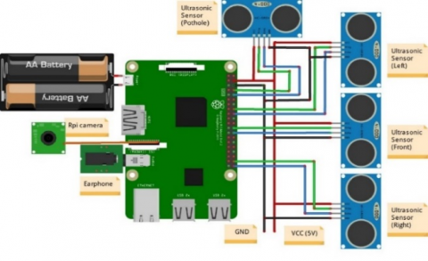
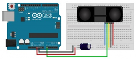
(a)
(b)
Figure 1. Circuit diagram of the developed spectacle (a) Raspberry-Pi based, and (b) Arduino-UNO based
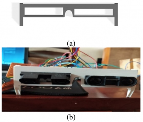
Figure 2. (a) Schematic diagram of the frame of spectacle, and (b) The final setup of the proposed system
In this paper, assistive technology is separated into two categories: Raspberry-pi-based technology and Arduino-based technology. The prototypes, developed in this paper, consists of four ultrasonic sensors, a Raspberry-Pi (for demonstrating Raspberry-pi based technology) or an Arduino Uno (for demonstrating Arduino-Uno-based technology), a headphone to alert the users, and a battery for the power supply. The circuit diagram is shown in Figure 1 where Figure 1(a) represents the prototype developed with Raspberry-Pi and Figure 1(b) represents the prototype developed with Arduino UNO. The prototype of an assistive technology-based system consists of four ultrasonic sensors, a Raspberry-Pi/Arduino Uno, a headphone to alert the users, and a battery for power supply. The circuit diagram is shown in Figure 1 where Figure 1(a) represents ultrasonic sensor setup with Raspberry-Pi and Figure 1(b) represents infrared sensor setup with Arduino UNO.
Figure 2 represents the frame of the spectacle which contains either Raspberry-Pi or Arduino-Uno-based prototype. From Figure 2(a), it can be monitored that the arm of the spectacle is on the x-axis. On the exterior side, the length, height, and width of the arm are 11.40, 2.52, and 0.50 cm respectively. Four holes are made for ultrasonic or infrared sensors where three of them detect the obstacles in the left, front and right directions, and the last one is for pothole detection on the road surface. The length, width, and thickness of the hole, created for ultrasonic or infrared sensor, is about 4.3, 2.0, and 1.5 cm respectively. Figure 2(b) represents the final setup of the proposed system.
A total of 100 vision-impaired people, from a blinds’ institute in Khulna, Bangladesh have been taken part in this study. Amongst them, 65 individuals are totally visually impaired, and 35 individuals are battling with some level of vision impedance. At first, we have assisted them to be familiar with different parts of the implemented system. We have helped them to practice with the signals that they would hear while moving, shown them the area of the sensors, and taught them how to utilize the framework. Several inquiries were made to receive feedback about the system. The review is driven in an outside environment in daylight conditions and the indoor climate of the blinds’ institute.
We have circulated the questionnaire to our members and restored all reactions they have observed. Aside from researching outside versatility encounters, the study would consider discovering contrasts between Raspberry-Pi and Arduino-based assistive technologies.
We have considered short inquiries and single decision questions. The study receives various decisions with remarks where participants are permitted to enter extra remarks. The multiple-choice answers generally originate from normal cases or circumstances in day-to-day life. Additionally, the multiple-choice answers help members better comprehend the comparing questions, yet in addition, consider their remarks.
3.1 Distance measurement range
In this study, the distance measurement feedback is first recorded from the participants. We have created five regions for positioning the obstacles. The regions are as follows.
We have circulated the questionnaire to the participants and recorded all reactions they got at long last. The short free content inquiries and single decision questions are considered for this survey. The study receives various decisions with remarks where participants are permitted to enter extra remarks. The multiple-choice answers are generally originated from normal cases or circumstances in day-to-day life. Additionally, the multiple-choice answers help members better comprehend the comparing questions, yet in addition, consider their remarks.
3.2 Survey questions in different environments
The questioning session includes two types of queries. Besides the individual’s information such as age, address, etc., other types of queries further lead to multiple-choice questions and single answered questions.
3.2.1 Questions in outdoor
In this part, questions related to user’s experience while visiting outdoor are asked, such as how often they roam outside, whether with a companion or solo, how to cross a busy road-crossing or junction, etc. These are detailed as follows.
Q1. How is the response in daylight, dim-light, and darkness?
Q2. How much comfortable is this technology while using at outdoor?
Q3. How is the response in gathering?
Q4. How is the response in road-crossing?
Q5. How is the response to a pothole?
3.2.2 Questions in indoor
In this part, several questions related to distance measurement are asked for the survey. These are shown as follows.
Q1. How is the realization of the obstacle at 0-10 m, 11-20 m, 21-50 m, 51-100 m, and 101-150 m distance?
Q2. How is the response in the staircase?
Q3. How is the response in using the washroom?
Q4. How is the response in detecting obstacles upon waist level?
Q5. How is the response in a classroom?
3.3 Barriers in environment
Visually weakened people often confront different types of barriers in both indoor and outdoor environments. In this section, these barriers are outlined shortly as follows.
3.3.1 Barriers in outdoor
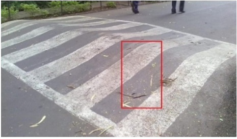
Outdoor barriers are of different types, and they can cause different inconveniences. Despite visually impaired people take some strategies to identify and avoid obstacles when they go out, they often face troubles because of pits, speed breakers, slopes, curbstones, types of terrain, etc. on the road surface. Troubles get even worse when they explore unfamiliar places instead of known surroundings. Figure 3 describes probable outdoor barriers along with water-filled pits and speed breakers.
3.3.2 Barriers in indoor
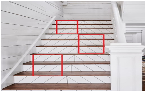
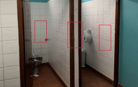
On the contrary, indoor barriers cause difficulties for vision weakened people in many aspects. A visually impaired person could face troubles not only in using washrooms or passing stairs but also in classrooms with unorganized benches, furniture-filled rooms, and so on. Figure 4 represents possible conventional indoor barriers that blind people face including stairs, washroom, classroom, and waiting room.
(a) Pit in the road
(b) Speed breaker on road
Figure 3. Few examples of barriers in the outdoor environment for visually impaired people
(a) Staircase
(b) Washroom
(c) Classroom
(d) Waiting room
Figure 4. Few examples of barriers indoors for visually impaired people
3.4 Distance measurement’s responses
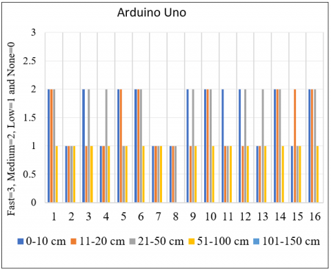
The survey is done by using Raspberry-pi and Arduino UNO-based systems. The practical data of this survey are presented in Table 1 and Table 2 which are collected for sixteen people. In both tables, responses’ levels are: None=0, Low=1, Medium=2 and Fast=3.
3.4.1 Responses from Raspberry-Pi
According to Table 1, we have received the same responses from 3rd, 4th, 5th, 10th, 11th, and 13th persons. Quick responses are observed for the distances: 0-10 cm, 11-20 cm, and 21-50 cm; medium and low responses are observed for 51-100 cm and 101-150 cm respectively.
The results from the 1st, 8th, and 14th persons are fully matched. The responses’ times of these persons are medium for the distance of 0-10 cm and 51-100 cm, are fast for 11-20 cm and 21-50 cm, and low for 101-150 cm. We have obtained the same results for 7th, 12th, and 16th persons where fast and low responses are observed for 21-50 and 101-150 cm respectively and medium responses are observed for 0-10, 11-20, and 51-100 cm. Another similarity is observed for 2nd and 9th persons. Obstacle detections’ responses’ times for these persons are fast for 11-20 cm, medium for 0-10, 21-50, and 51-100 cm, and low for 101-150 cm. Different results have been observed from the 6th and 15th persons.
Table 1. Distance measurement by using Raspberry-pi
|
Person |
0-10 cm |
11-20 cm |
21-50 cm |
51-100 cm |
101-150 cm |
|
1 |
2 |
3 |
3 |
2 |
1 |
|
2 |
2 |
3 |
2 |
2 |
1 |
|
3 |
3 |
3 |
3 |
2 |
1 |
|
4 |
3 |
3 |
3 |
2 |
1 |
|
5 |
3 |
3 |
3 |
2 |
1 |
|
6 |
2 |
2 |
3 |
1 |
1 |
|
7 |
2 |
2 |
3 |
2 |
1 |
|
8 |
2 |
3 |
3 |
2 |
1 |
|
9 |
2 |
3 |
2 |
2 |
1 |
|
10 |
3 |
3 |
3 |
2 |
1 |
|
11 |
3 |
3 |
3 |
2 |
1 |
|
12 |
2 |
2 |
3 |
2 |
1 |
|
13 |
3 |
3 |
3 |
2 |
1 |
|
14 |
2 |
3 |
3 |
2 |
1 |
|
15 |
3 |
3 |
2 |
2 |
1 |
|
16 |
2 |
2 |
3 |
2 |
1 |
Figure 5 represents the graphical view of distance measurement by using Raspberry-Pi for 16 people. Sixteen participants are marked by different colors to simplify the visualization. Here Y-axis plots the level of the responses, and the X-axis plots the distances covered by the 16 people.
3.4.2 Responses from Arduino uno
According to Table 2, we have obtained the same results for the 1st, 6th, 10th, 14th, and 16th persons. Responses’ times are medium for 0-10 cm, 11-20 cm, and 21-50 cm. For 51-100 cm, response time for obstacle detection is obtained as low. The worst thing is, if an obstacle exists within 101-150 cm then the Arduino-based system cannot detect this. The same results are achieved from the 3rd, 9th, and 12th persons. Responses’ levels are the medium for 0-10 cm and 21-50 cm and low for 11-20 and 51-100 cm. The system has failed to detect an object in 101-150 cm. The results from the 2nd and 7th persons are fully matched. Here, obstacle detection’s response level are low for 0-10 cm, 11-20 cm, 21-50 cm, and 51-100 cm. Obstacles between 101-150 cm are undetectable. Another similarity has appeared when we have checked the data of the 4th and 13th persons. In this case, responses’ times are low for 0-10 cm, 11-20 cm, and 51-100 cm. For 21-50 cm, it is medium. The obstacles are undetectable within 101-150 cm.
Table 2. Distance measurement by using Arduino
|
Person |
0-10 cm |
11-20 cm |
21-50 cm |
51-100 cm |
101-150 cm |
|
1 |
2 |
2 |
2 |
1 |
0 |
|
2 |
1 |
1 |
1 |
1 |
0 |
|
3 |
2 |
1 |
2 |
1 |
0 |
|
4 |
1 |
1 |
2 |
1 |
0 |
|
5 |
2 |
2 |
1 |
1 |
0 |
|
6 |
2 |
2 |
2 |
1 |
0 |
|
7 |
1 |
1 |
1 |
1 |
0 |
|
8 |
1 |
1 |
1 |
0 |
0 |
|
9 |
2 |
1 |
2 |
1 |
0 |
|
10 |
2 |
2 |
2 |
1 |
0 |
|
11 |
2 |
1 |
1 |
1 |
0 |
|
12 |
2 |
1 |
2 |
1 |
0 |
|
13 |
1 |
1 |
2 |
1 |
0 |
|
14 |
2 |
2 |
2 |
1 |
0 |
|
15 |
1 |
2 |
1 |
1 |
0 |
|
16 |
2 |
2 |
2 |
1 |
0 |
Figure 5. Distance measurement response for Raspberry-Pi
Figure 6 represents the graphical view of distance measurement by using Arduino for 16 people. Sixteen participants are marked by different colors to simplify the visualization. Here, the Y-axis plots the level of the responses, and the X-axis plots the distances covered by the 16 people. The main difference between Raspberry-Pi and Arduino is that there are no fast responses by Arduino. We have observed “Medium” responses (obtained by Raspberry-Pi) as the highest responses by Arduino.
Figure 6. Distance measurement responses from Arduino based system
3.5 Survey results’ analysis
By analyzing the results of Tables 1 and 2, we can observe that the Raspberry-Pi-based system has greater obstacle detection capability than the Arduino-UNO-based system. If we go through both tables at a time, then we will be able to find the major problems of Arduino based obstacle detection system. These are-
The detection range of Arduino based system is lower than Raspberry-Pi. If an obstacle exists between 101-150 cm, then Arduino based system cannot detect this properly. If there is an object in between then it will be undetected. In this case, we can say “Larger the distance, lower the detection capability”.
From the above discussion, it can be concluded that the Arduino-based detection system would not be a handy tool in a real-life scenario. The relative activity and efficiency of the Raspberry-Pi-based detection system are much better.
3.5.1 Persons’ specific performance measurement
For more accurate performance measurement, we have divided the range of 0-150 cm into 16 sections and covered the survey with two persons. As an example, for a blind and a low vision person, the observed survey report is shown below.
Person 1: Rakib Ahmed
Age: 11 years
Condition: Blind
Person 2: Mostafiz
Age: 12 years
Condition: Low vision
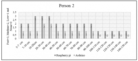
Table 3 shows the comparison between Raspberry-Pi-based assistive devices and tose of Arduino-based depending on devices’ responses for the blind and the low vision people. It shows the relative analysis of distance measurements for Person 1 and Person 2 by using Raspberry-Pi and Arduino.
Table 3. The response of the proposed device for various distance measurement
|
Distance |
Person-1 |
Person-2 |
||
|
|
Raspberry |
Arduino |
Raspberry |
Arduino |
|
5-7 cm |
medium |
medium |
medium |
slow |
|
7-10 cm |
medium |
medium |
medium |
slow |
|
10-20 cm |
fast |
medium |
fast |
slow |
|
20-30 cm |
fast |
medium |
fast |
medium |
|
30-40 cm |
fast |
medium |
fast |
medium |
|
40-50 cm |
fast |
medium |
medium |
slow |
|
50-60 cm |
medium |
slow |
medium |
slow |
|
60-70 cm |
medium |
slow |
medium |
slow |
|
70-80 cm |
medium |
slow |
medium |
slow |
|
80-90 cm |
medium |
slow |
medium |
slow |
|
90-100 cm |
medium |
slow |
medium |
slow |
|
100-110 cm |
medium |
slow |
slow |
none |
|
110-120 cm |
medium |
slow |
slow |
none |
|
120-130 cm |
medium |
none |
slow |
none |
|
130-140 cm |
slow |
none |
slow |
none |
|
140-150 cm |
slow |
none |
slow |
none |
|
Responses’ Levels |
34 |
19 |
30 |
13 |
Here, the responses of Raspberry-Pi for Person 1 and Person 2 are 34 and 30 respectively. On the other hand, the responses of Arduino for Person 1 and Person 2 are 19 and 13 respectively. From these results, we can observe that both the responses’ values of Arduino based system are much lower than Raspberry-Pi based system. The average responses of the Raspberry-Pi-based system (taking these two participants) are 32 where Arduino has only 16 which is a total of half of the Raspberry-Pi-based system.
Figure 7. Comparison of distance measurement for person 1 by using Raspberry-Pi and Arduino
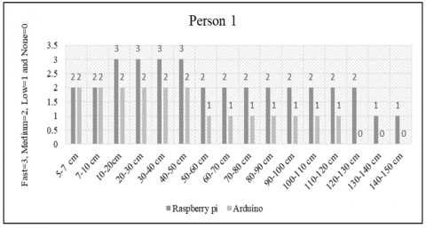
The outputs of the Raspberry-Pi and Arduino-based system for person 1 are plotted in Figure 7. An eleven-year-old boy named Rakib Ahmed is considered as “Person 1” who is blind by birth. We have experimented with both systems with him to check the performance of those systems according to real-world circumstances. In this whole graph, only in two-interval, both systems work fully the same. These intervals are 5-7 cm and 7-10 cm. But after that, during the rest of the intervals, the response of Arduino is not good enough. When the object exists among 10-20 cm, 20-30 cm, 30-40 cm, and 40-50 cm then the Raspberry-Pi-based system can detect the object with “Fast” responses’ time.
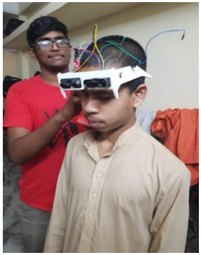
On the other hand, Arduino based system’s response time is medium. For 50-60 cm, 60-70 cm, 70-80 cm, 80-90 cm, 90-100 cm, 100-110 cm, and 110-120 cm, object detections’ responses time are medium Raspberry-Pi and slow in Arduino based system. If the objects are existing in between 120-130 cm, then we have obtained medium responses’ time from a Raspberry-Pi based detection system. However, Arduino based system failed to detect the object at the same distance. In 130-140 cm and 140-150 cm, responses’ times are slower than Raspberry-Pi-based system. In between 130-140 cm and 140-150 cm, an Arduino-based system can detect nothing. Since a detection system is considered as an effective and applicable system based on its detection capability and the object detection capability of Arduino based system is lower than the Raspberry-Pi based system, we can conclude for the case of Person 1 that the Raspberry-Pi based system is more effective and applicable in a real-life scenario. A real-time experiment on “Person 1” is captured in Figure 8.
The responses’ time of Raspberry-Pi-based system are medium among 5-7 cm, 7-10 cm, 40-50 cm, 50-60 cm, 60-70 cm, 70-80 cm, 80-90 cm and 90-100 cm. In the same case, the responses’ times of Arduino based system are slow. When objects are found between 10-20 cm then the Raspberry-Pi-based system responded faster than Arduino based system. In between 20-30 cm and 30-40 cm, responses’ times are fast and medium for Raspberry-Pi and Arduino-based systems respectively. In between 100-110 cm, 110-120 cm, 120-130 cm, 130-140 cm, and 140-150 cm, the Raspberry-Pi-based system can detect the objects but it takes a larger time for detection. However, in these cases, the responses’ times of Raspberry-Pi are lower than Arduino. If the objects are existing in between 100-110 cm, 110-120 cm, 120-130 cm, 130-140 cm, and 140-150 cm then the system cannot detect these. A real-time experiment on “Person 2” is captured in Figure 10.
Figure 8. Real-time experiment on “Person 1”
Figure 9. Comparison of distance measurement for person 2 by using Raspberry-Pi and Arduino
The outputs of the Raspberry-Pi and Arduino-based system for person 2 are plotted in Figure 9. A twelve year’s old boy named Mostafiz is considered (Person 2) who is suffering from a low vision problem. We have also experimented with both systems with him to check the performance in real life. From this graph, it can be observed that the Raspberry-Pi-based system is dominating over Arduino based system.
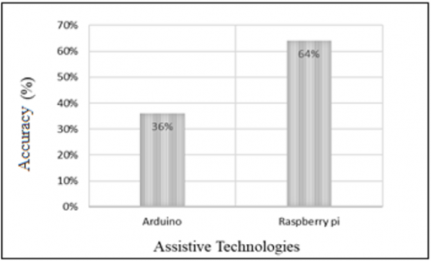
Based on measured distances by the developed system (both Raspberry-Pi based and Arduino based) and actual distances (measured manually), the accuracy is calculated. The formula to derive the values of accuracy is shown in (1).
Accuracy $=\frac{(T P+T N)}{(T P+T N+F P+F N)}$ (1)
The accuracies of both systems are plotted in Figure 11. Here the Raspberry-Pi-based system’s accuracy is 64% and the Arduino-based system’s accuracy is only 36%. It can be observed from the figure that, the Raspberry-Pi based system has better accuracy than the Arduino-based system.
Figure 10. Real-time experiment on “Person 2”
Figure 11. Accuracy of distance measurements by Raspberry-Pi and Arduino
Besides the above-mentioned survey, some other parameters are also analysed for the study of performance analysis.
4.1 Cost and carrying techniques
The required costs are discussed for Raspberry-Pi and Arduino-based systems. During the survey, 82% reacted that the price is reasonable, the cost is relatively high for the 5% people and remaining 13% treated the cost as moderate. About the carrying techniques for both Raspberry-pi based, and Arduino based systems, almost none of the participants' complaint regarding this.
4.2 Size and weight
For the implementation of the spectacle, some hardware devices are used like Raspberry-Pi, distance measurement sensors (ultrasonic sensors), Arduino, headphones, etc. The model of the walking assistance is built effectively with a weight of about 400 gm for Raspberry-Pi and 385 g for Arduino including all electronic components. In case of size and weight, 73% responded that the size and weight are significant, 20% treated that the size isn't reasonable, and weight needs to be decreased, and the rest 7% individuals reacted that the framework is massive.
4.3 Input signal observation
Concerning signal perception, 98% responded that the sound was clear to them and the excess 2% of people missed hearing the audio signal. However, when we deeply investigated the issue, we have come to know from the participants that the people, who could not hear the sound appropriately, have hearing problems. Table 4 illustrates the performance comparison among the proposed method (here we have chosen Raspberry-Pi-based system) and existing methods. It can be observed from this table that the proposed method works both in indoor and outdoor environments, covers the highest detection range, and consumes lesser weight and cost. Though the assistive devices proposed by Sharma et al. [24] and Vera et al. [25] require low costs, they consume high weight.
Table 4. The performance comparison among the proposed method and existing methods
|
Authors |
Coverage Area |
Detection Range |
Weight |
Cost |
|
Sharma et al. [24] |
Indoor |
0.05m - 3.5m |
High weight |
Low cost |
|
Ton et al. [8] |
Indoor |
2m-4m |
170 gram |
High cost |
|
Rizvi et al. [10] |
Indoor and outdoor |
0.09m- 0.20m |
Bulky but wearable |
High cost |
|
Vera et al. [25 |
Indoor and outdoor |
1m-2.5m |
Bulky |
Low cost |
|
Proposed System |
Indoor and outdoor |
1m-5.5m |
A few hundred grams |
Low cost |
This paper studies the functionalities and performances of assistive devices developed for the visually impaired in real-life scenarios. To evaluate the performance of the walking assistance technologies developed by Raspberry-Pi and Arduino-based systems, we have experimented with the visually impaired people in a Madrasah (Established mainly for the blinds). Analyzing the data from the real-life experiments, it can be concluded that the Raspberry-pi-based system is more efficient than Arduino based system for obstacle detection. Overall, the accuracy of the Raspberry-Pi based system is 64% and the Arduino-based system is only 36%. In the future, we will focus on the development of a system-on-chip (SoC) in order to reduce the size, weight, and cost of the developed system.
[1] Islam, M.M., Sadi, M.S., Bräunl, T. (2020). Automated walking guide to enhance the mobility of visually impaired people. IEEE Transactions on Medical Robotics and Bionics, 2(3): 485-496. https://doi.org/10.1109/TMRB.2020.3011501
[2] Favey, C., Zogaghi, A., Leroux, R., Vivan, B., Farcy, R. (2020). Autonomous navigation of a visually impaired person with loss of limb sensitivity, via a smart wheelchair (case study). Modelling, Measurement and Control C, 81(1-4): 30-34. https://doi.org/10.18280/mmc_c.811-406
[3] Meshram, V.V., Patil, K., Meshram, V.A., Shu, F.C. (2019). An astute assistive device for mobility and object recognition for visually impaired people. IEEE Transactions on Human-Machine Systems, 49(5): 449-460. https://doi.org/10.1109/THMS.2019.2931745
[4] Jafri, R., Campos, R.L., Ali, S.A., Arabnia, H.R. (2017). Visual and infrared sensor data-based obstacle detection for the visually impaired using the Google project tango tablet development kit and the unity engine. IEEE Access, 6: 443-454. https://doi.org/10.1109/ACCESS.2017.2766579
[5] Islam, M.M., Sadi, M.S., Zamli, K.Z., Ahmed, M.M. (2019). Developing walking assistants for visually impaired people: A review. IEEE Sensors Journal, 19(8): 2814-2828. https://doi.org/10.1109/JSEN.2018.2890423
[6] Cardillo, E., Di Mattia, V., Manfredi, G., Russo, P., De Leo, A., Caddemi, A., Cerri, G. (2018). An electromagnetic sensor prototype to assist visually impaired and blind people in autonomous walking. IEEE Sensors Journal, 18(6): 2568-2576. https://doi.org/10.1109/JSEN.2018.2795046
[7] Bai, J., Lian, S., Liu, Z., Wang, K., Liu, D. (2018). Virtual-blind-road following-based wearable navigation device for blind people. IEEE Transactions on Consumer Electronics, 64(1): 136-143. https://doi.org/10.1109/TCE.2018.2812498
[8] Ton, C., Omar, A., Szedenko, V., Tran, V.H., Aftab, A., Perla, F., Yang, Y. (2018). LIDAR assist spatial sensing for the visually impaired and performance analysis. IEEE Transactions on Neural Systems and Rehabilitation Engineering, 26(9): 1727-1734. https://doi.org/10.1109/TNSRE.2018.2859800
[9] Ramadhan, A.J. (2018). Wearable smart system for visually impaired people. Sensors, 18(3): 843. https://doi.org/10.3390/s18030843
[10] Rizvi, S.T.H., Asif, M.J., Ashfaq, H. (2017). Visual impairment aid using haptic and sound feedback. In 2017 International Conference on Communication, Computing and Digital Systems (C-CODE), pp. 175-178. https://doi.org/10.1109/C-CODE.2017.7918924
[11] Prattico, F., Cera, C., Petroni, F. (2013). A new hybrid infrared-ultrasonic electronic travel aids for blind people. Sensors and Actuators A: Physical, 201: 363-370. https://doi.org/10.1016/j.sna.2013.06.028
[12] Mancini, A., Frontoni, E., Zingaretti, P. (2018). Mechatronic system to help visually impaired users during walking and running. IEEE Transactions on Intelligent Transportation Systems, 19(2): 649-660. https://doi.org/10.1109/TITS.2017.2780621
[13] Jiang, B., Yang, J., Lv, Z., Song, H. (2018). Wearable vision assistance system based on binocular sensors for visually impaired users. IEEE Internet of Things Journal, 6(2): 1375-1383. https://doi.org/10.1109/JIOT.2018.2842229
[14] Li, B., Munoz, J.P., Rong, X., Chen, Q., Xiao, J., Tian, Y., Yousuf, M. (2018). Vision-based mobile indoor assistive navigation aid for blind people. IEEE Transactions on Mobile Computing, 18(3): 702-714. https://doi.org/10.1109/TMC.2018.2842751
[15] Ye, C., Hong, S., Qian, X., Wu, W. (2016). Co-robotic cane: A new robotic navigation aid for the visually impaired. IEEE Systems, Man, and Cybernetics Magazine, 2(2): 33-42. https://doi.org/10.1109/MSMC.2015.2501167
[16] Mulky, R.S., Koganti, S., Shahi, S., Liu, K. (2018). Autonomous scooter navigation for people with mobility challenges. In 2018 IEEE International Conference on Cognitive Computing (ICCC), pp. 87-90. https://doi.org/10.1109/ICCC.2018.00020
[17] Xiao, J., Ramdath, K., Losilevish, M., Sigh, D., Tsakas, A. (2013). A low cost outdoor assistive navigation system for blind people. In 2013 IEEE 8th Conference on Industrial Electronics and Applications (ICIEA), pp. 828-833. https://doi.org/10.1109/ICIEA.2013.6566481
[18] Cheraghi, S.A., Namboodiri, V., Walker, L. (2017). GuideBeacon: Beacon-based indoor wayfinding for the blind, visually impaired, and disoriented. In 2017 IEEE International Conference on Pervasive Computing and Communications (PerCom), pp. 121-130. https://doi.org/10.1109/PERCOM.2017.7917858
[19] Ţepelea, L., Gavriluţ, I., Gacsadi, A. (2017). Smartphone application to assist visually impaired people. In 2017 14th International Conference on Engineering of Modern Electric Systems (EMES), pp. 231. https://doi.org/10.1109/EMES.2017.7980421
[20] Alghamdi, S., van Schyndel, R., Khalil, I. (2014). Accurate positioning using long range active RFID technology to assist visually impaired people. Journal of Network and Computer Applications, 41: 135-147. https://doi.org/10.1016/j.jnca.2013.10.015
[21] Nakajima, M., Haruyama, S. (2013). New indoor navigation system for visually impaired people using visible light communication. EURASIP Journal on Wireless Communications and Networking, 2013(1): 1-10. https://doi.org/10.1186/1687-1499-2013-37
[22] Pape, T.L.B., Kim, J., Weiner, B. (2002). The shaping of individual meanings assigned to assistive technology: A review of personal factors. Disability and rehabilitation, 24(1-3): 5-20. https://doi.org/10.1080/09638280110066235
[23] Mocanu, B., Tapu, R., Zaharia, T. (2016). When ultrasonic sensors and computer vision join forces for efficient obstacle detection and recognition. Sensors, 16(11): 1807. https://doi.org/10.3390/s16111807
[24] Sharma, S., Gupta, M., Kumar, A., Tripathi, M., Gaur, M. S. (2017. Multiple distance sensors based smart stick for visually impaired people. In 2017 IEEE 7th Annual Computing and Communication Workshop and Conference (CCWC), pp. 1-5. https://doi.org/10.1109/CCWC.2017.7868407
[25] Vera, D., Marcillo, D., Pereira, A. (2017). Blind guide: Anytime, anywhere solution for guiding blind people. In World Conference on Information Systems and Technologies, pp. 353-363. https://doi.org/10.1007/978-3-319-56538-5_36