Kapil Dev Yadav* | Radha Krishna Prasad
OPEN ACCESS
This paper deals with the theoretical analysis of a parallel flow solar air heater (SAH) having an absorber plate roughened with arc shaped wires. The absorber plate that forms the upper and lower ducts is roughened on its upper side only. A mathematical model describing the fluid flow and heat transfer characteristics of such a parallel flow roughened absorber plate SAH has been developed to study the effects of various operating and systems parameters on thermal performance of the SAH. The governing energy equations have been solved by iterative method using computer codes in MATLAB. A comparison between the theoretical results obtained and experimental results available in the literature has been made which shows a good agreement between the results. The thermal efficiency of parallel flow roughened SAH has been found nearly 8-10% higher than the smooth parallel flow SAH operating under similar conditions.
parallel flow solar air heater, artificial roughness, thermal efficiency, thermohydraulic efficiency, heat transfer coefficients
Energy is main agent in wealth generation and economic development. The demand of energy is increasing greatly day-by-day because of rapid increase in the world population. Generation of power from non-renewable energy sources causes environmental degradation. Hence there is a need for harnessing non-conventional energy resources. Among all the non-conventional (renewable) energy resources, the solar energy is the most abundant, freely available, and inexhaustible clean energy source. The solar energy is directly converted into electrical energy by photovoltaic solar cell and into thermal energy using solar collectors (solar air and water heaters) [1].
A solar air heater is very useful for low grade thermal energy applications such as space heating, timber curing and drying of agricultural products etc. due to its simple construction and easy operation, low maintenance and low capital costs. The performance of a solar collector depends upon how much heat is picked up by working fluid from the collector. The performance of the solar air heater can be increased by - increasing the heat transfer coefficient between the absorber plate and the air by using artificially roughened absorber plates, increasing the heat transfer area by using fins on absorber plate or packing the duct with porous absorber materials.
The low heat transfer coefficient, thereby, low heat transfer rate between flat plate absorber and air causes lower thermal efficiency of flat plate solar air heater. When air flows through the duct of a solar air heater, a laminar sub-layer is formed adjacent to absorber surface that decreases the heat transfer to the flowing air and so the thermal efficiency. The use of artificial roughness on the absorber plate on air flow side breaks the viscous sub-layer formed in the zone of turbulent boundary layer which creates local wall turbulence adjacent to the surface of absorber plate and hence heat transfer coefficient and therefore rate of heat transfer between absorber plate and air flowing over the absorber increases. Energy required to create turbulence comes from the blower or fan thus, excessive turbulence may result in greater power requirements for the blower, which requires a judicious choice of roughness element and its geometry [1].
The artificial roughness on the absorber surface of SAH can be created by several methods such as providing sand grains roughness by sand blasting the surface, using dimple shaped protrusion and rib type roughness. The artificial roughness could be of several shapes such as groove and ridge type or rib type, fins and wires.
The Researchers have been tried different designs of roughness elements in the past which increase heat transfer with acceptable frictional losses. A review on use of roughness elements of different geometries in SAH has been presented by Saini and Singal [2]. Saini, S.K. and Saini, R.P. [3] have developed correlations for Nusselt number and friction factor for SAH having arc-shaped wires as artificial roughness on the absorber plate. Ozgen et al. [4] performed experimental investigation on thermal performance of a double-flow SAH having aluminium cans. Prasad and Saini [5] have conducted experimental investigation of heat transfer and flow friction characteristics for artificially roughened SAH duct with transverse rib roughness. An analytical model of thermal performance of double parallel flow and double pass counter flow has been developed by Hernández and Quiñonez [6]. Yadav and Kaushal [7] performed exergy analysis of solar air heater having arc shape oriented protrusions as roughness element. Gill et al. [8] obtained heat transfer and friction characteristics of solar air heater having broken arc shaped ribs combined with staggered rib piece on absorber plate. Sahu and Prasad [9] performed thermohydraulic analysis of an arc shape wire roughened single flow SAH. Gabhane and Kanase-Patil [10] performed experimental analysis of double flow solar air heater with multiple C- shape roughness.
A summary of correlations developed/used by different researchers for performance evaluation of SAHs with different roughness elements and geometries are given in Table 1.
The previous literature reveals that roughened SAHs perform much better than the conventional SAH because of the turbulence created near the absorber plate surface. The investigation of thermal performance of parallel flow solar air heaters has been of considerable interest of the previous researchers. In view of this, an analytical study of parallel flow SAH with arc-shape wires as artificial roughness on absorber plate has been performed to investigate the effects of various system and operating parameters on the thermal performance and to arrive at conclusions which may be useful for a designer to design such SAH. The galvanised iron (GI) wires in form of parallel arc-shape have been considered as roughness on the absorber plate at upper duct, formed between absorber plate and glass cover, and back side of the absorber plate as smooth which forms the lower duct. The parameters such as relative roughness height (e/d = 0.02 to 0.06), Reynolds number (Re = 1000 to 40,000), collector length (L = 1 to 2.5 m), duct depth (H= 0.02 to 0.2 m), solar insolation (S = 800 to 1000W/m2), atmospheric air temperature (Ta = 300 to 330 K) and relative arc angle (α/90 = 0.45) have been considered for evaluation of the theoretical results.
Table 1. Few important works on roughened solar air heaters
|
Authors |
Range of roughness elements & operating Parameters |
Correlations developed/used by the authors |
|
Saini, S.K. and Saini, R.P. [3] |
Arc-shaped wire e/d = 0.0213 to 0.0422 α/90 = 0.3333 to 0.6666 Re = 2000 to 17,000 |
Nu= 0.001047Re1.3186(e/d)0.3772(α/90)0.1198 f = 0.14408Re0.17103(e/d)0.1765(α/90)0.1185 |
|
Ozgen et al. [4] |
Aluminium cans m = 0.03 kg/s and 0.05 kg/s |
$\eta_{m=0.03}=0.5906-13.774\left[\frac{T_{a, i n}-T_{a m b}}{I}\right]$ $\eta_{m=0.05}=0.7273-14.900\left[\frac{T_{a, i n}-T_{a m b}}{I}\right]$ |
|
Prasad and Saini [5] |
Transverse rib wires e/D = 0.020-0.033 P/e = 10-20 Re = 5000-50000 |
$S t=\frac{\frac{f}{2}}{1+\sqrt{\frac{f}{2}}\left[4.5\left(e^{+}\right)^{0.28} \operatorname{Pr}^{0.57}-0.95(P / e)^{0.53}\right]}$ $f=\frac{2}{\left[0.95(P / e)^{0.53}+2.5 \ln (D / 2 e)-3.75\right] \quad ^{2}}$ |
|
Yadav and Kaushal [7] |
Arc shape protrusions as roughness e/d = 0.015–0.03 P/e = 12–24 Re = 1000–40,000 Arc angle, α = 45–75o UL = 5W/m2 K ΔT/G = 0.06–0.0025 K m2/W |
$N u=0.154 \times R e^{1.017} \times\left(\frac{P}{e}\right)^{-0.38} \times\left(\frac{e}{d}\right)^{0.521} \times\left(\frac{\alpha}{60}\right)^{-0.213} \times$$\exp \left(-2.023\left(\ln \left(\frac{\alpha}{60}\right)\right)^{2}\right) f$ $=7.207 \times R e^{-0.56} \times\left(\frac{P}{e}\right)^{-0.18} \times\left(\frac{e}{d}\right)^{0.176} \times\left(\frac{\alpha}{60}\right)^{0.038}$$\times \exp \left(-1.412\left(\ln \left(\frac{\alpha}{60}\right)\right)^{2}\right)$ |
|
Sahu and Prasad [9] |
Arc shape wire Re = 2000-35,000 I = 600-1000 W/m2 H = 0.030-0.050 m |
f = 0.085Re-0.25 for smooth plate solar heater f = 0.14408Re-0.17103(e/d)0.1765(α/90)0.1185 Nu= 0.001047Re1.3186(e/d)0.3772(α/90)0.1198 |
|
Gabhane and Kanase-Patil [10] |
Multiple C shape roughness Re = 3000, 6000, 9000, 12000, 15000 P/e = 8, 16, 24, 32, 40 α = 30, 45, 60 |
Nu= 0.20627(Re)-0.8087(P/e)0.03724(α/90)0.2735 f = 0.9123(Re)-0.28379(P/e)-0.14847 (α/90)-0.12127 St = 0.27234(Re)-0.19129(P/e)-0.03725 (α/90)0.27358 TPP = 2.21212(Re)0.041(P/e)0.01857 (α/90)0.31078 |
|
Gupta et al. [11] |
Transverse wires 5 ˂ e+ ˂ 70 Re = 3000 – 18000 e/D = 0.018 – 0.052 P/e = 10 W/H = 6.8 – 11.5 |
$f=0.06412(e / D)^{0.019}(W / H)^{0.237}(R e)^{-0.185}$ $N u=0.00307(e / D)^{-0.469}(W / H)^{0.245} R e^{0.812}$ |
|
Verma and Prasad [12] |
Transverse wire ribs e/D = 0.040 P/e = 10 I = 800 W/m2 |
For Re+ ≤ 24 $N u=0.08596(e / D)^{0.072}(P / e)^{-0.054} R e^{0.732}$ For Re+ ˃ 24 $N u=0.02954(e / D)^{0.021}(P / e)^{-0.016} R e^{0.802}$ $f=0.0245(e / D)^{0.243}(P / e)^{-0.206} R e^{-1.25}$ |
|
Momin et al. [13] |
V-shape ribs e/D = 0.02-0.034 P/e = 10 Re=2500-18000 α=30°-60° |
$N u=0.067(e / d) 0.424(\alpha / 60)-0.077 \operatorname{Re} 0.888$ $\exp \left[-0.782 \ln (\alpha / 60)^{2}\right]$ $f=6.266(e / D)^{0.565}(\alpha / 60)^{-0.093} R e^{-0.425}$ $\exp \left[-0.719\{\ln (\alpha / 60)\}^{2}\right]$ |
|
Ho et al. [14] |
SAH with recycle m = 38.52, 57.96 and 77.04 kg/s I = 830 and 1100 J/s m2 |
$N u_{i}=\frac{h_{i} D_{h}}{k}=0.0158 \operatorname{Re}_{h, i}^{0.8}\left[1+\left(D_{h i} / L\right)^{0.7}\right], i=1,2$ |
|
Karmare and Tikekar [15] |
Metal grit ribs e/D = 0.040 P/e = 10 l/s = 1.72 I = 800 W/m2 |
$N u=2.4 \times 10^{-3} \times R e^{1.3}(e / D)^{0.42}$$(l / s)^{-0.146} \times(P / e)^{-0.27}$ $f=15.55 \times R e^{-0.263} \times(e / D)^{0.91}$$(l / s)^{-0.27} \times(P / e)^{-0.51}$ |
|
Aharwal et al. [16] |
Inclined rib with gap e/D = 0.0377 P/e = 10 Re = 3000-18000 α = 60° L2/H = 5.84 g/e = 0.5-2.0 d/w = 0.1667-0.667 |
$N u=0.012 R e^{1.148}(e / D)^{0.51}$ $\left[1-(0.25-d / w)^{2}\left(0.01(1-g / e)^{2}\right)\right]$ $f=0.5 R e^{-0.0836}(e / D)^{0.72}$ |
|
Gupta and Kaushik [17] |
Metal mesh Roughened absorber plate e/d = 0.01-0.05 Relative short way lengths s/e = 15-45, V∞ = 1.5 m/s β = 30o, Ts = 5600K e = Rib height (m) s = short way of mesh, entropy (mJ/kg K) |
$N u=40 \times 10^{-4} R e^{1.22} \times\left(\frac{e}{d_{e}}\right)^{0.625} \times\left(\frac{s}{10 e}\right)^{2.22} \times\left(\frac{l}{10 e}\right)^{2.66} \times$ $\exp \left(-1.25\left(\ln \left(\frac{s}{10 e}\right)\right)^{2}\right) \times \exp \left(-0.824\left(\ln \left(\frac{l}{10 e}\right)\right)^{2}\right)$ For Smooth duct f = 0.0791(Re)−0.25 For roughened duct $f=0.815 \times R e^{-0.361} \times\left(\frac{P}{e}\right)^{-0.18} \times\left(\frac{10 e}{d_{e}}\right)^{0.591} \times\left(\frac{l}{e}\right)^{0.266} \times\left(\frac{s}{10 e}\right)^{-0.19}$ |
|
Hans et al. [18] |
Multiple V-ribs e/D = 0.019-0.043 P/e = 6-12 Re = 2000-20000 α = 30-60° W/w = 1-10 |
$N u=3.35 \times 10^{-5} R e^{0.92}(e / D)^{0.77}(W / w)^{0.43}(\alpha / 90)^{-0.49}$ $\exp \left[-0.1177(\ln (W / w))^{2}\right] \exp \left[-0.061(\ln (\alpha / 90))^{2}\right]$ $(P / e) 0.854 \exp \left[-2.0407(\ln (P / e))^{2}\right]$ $f=4.47 \times 10^{-4} R e^{-0.3188}(e / D)^{0.73}(W / w)^{0.22}$ $(\alpha / 90)^{-0.39} \exp \left[-0.52(\ln (\alpha / 90))^{2}\right]$ $(P / e)^{8.9} \exp \left[-2.133(\ln (P / e))^{2}\right]$ |
|
Bhushan and Singh [19] |
Protruded ribs e/D = 0.03 S/e = 18.75-37.50 L/e = 25-37.50 d/D = 0.147-0.367 Re = 4000-20000 L2/H = 10 |
$N u=2.1 \times 10^{-88} R e^{1.452}(S / e)^{12.94}(L / e)^{99.2}(d / D)^{-3.9}$ $\times \exp \left[-10.4\{\ln (S / e)\}^{2}\right]$ $\times \exp \left[-77.2\{\ln (L / e)\}^{2}\right] \exp \left[-7.83\{\ln (d / D)\}^{2}\right]$ $f=2.3 \times R e^{-0.201}(S / e)^{-0.383}(L / e)^{-0.484}(d / D)^{0.133}$ |
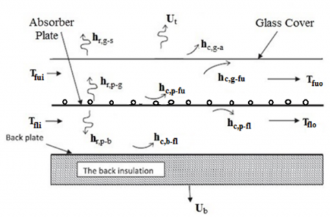
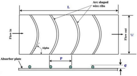
A parallel flow SAH having arc shaped wires on the absorber plate in upper duct side and smooth in lower duct side as shown in Figure 1, has been considered for analysis. The SAH consists of single glass cover, a single side roughened absorber plate, smooth back plate. The glass cover and roughened absorber plate forms upper duct and lower duct is formed between absorber plate and back plate. Two parallel air stream is flowing steadily with same or different mass flow rates in upper and lower ducts to be heated. Different heat transfer coefficients involved in the analysis are shown in the Figure 1(a) and top view (upper duct side) of the absorber plate is shown in the Figure 1(b).
Figure 1. (a) Heat transfer coefficients in the double-flow solar air heater. (b) Arc shape absorber plate with wire rib roughness
2.1 Energy balance equations
The energy balance equations for the system are presented below with the following assumptions undertaken.
For glass cover
$\alpha_{g} S+h_{r, p-g}\left(T_{p}-T_{g}\right)$$+h_{c, g-f_{u}}\left(T_{f_{u}}-T_{g}\right)-U_{t}\left(T_{g}-T_{a}\right)=0$ (1)
For air flowing between glass cover and absorber plate
$h_{c, p-f_{u}}\left(T_{p}-T_{f_{u}}\right)+h_{c, g-f_{u}}\left(T_{g}-T_{f u}\right)-q_{u_{1}}=0$ (2)
For absorber plate
$\alpha_{p} \tau_{g} S-h_{r, p-g}\left(T_{p}-T_{g}\right)-h_{c, p-f_{u}}\left(T_{p}-T_{f_{u}}\right)$$-h_{r, p-b}\left(T_{p}-T_{b}\right)-h_{c, p-f_{l}}\left(T_{p}-T_{f_{l}}\right)=0$ (3)
For air flowing between absorber plate and base plate
$h_{c, p-f_{l}}\left(T_{p}-T_{f_{l}}\right)+h_{c, p-f_{l}}\left(T_{b}-T_{f_{l}}\right)-q_{u_{2}}=0$ (4)
For back plate
$h_{r, p-b}\left(T_{p}-T_{b}\right)-h_{c, b-f_{l}}\left(T_{b}-T_{f_{l}}\right)$$-U_{b}\left(T_{b}-T_{a}\right)=0$ (5)
After rearranging Eq. (1), the glass cover temperature Tg is given by
$T_{g}=\frac{U_{t} T_{a}+h_{c, g-f_{u}} T_{f_{u}}+h_{r, p-g} T_{p}}{U_{t}+h_{c, g-f_{u}}+h_{r, p-g}}$ (6)
Similarly, the temperature of the back plate Tb is given by rearranging the Eq. (5)
$T_{b}=\frac{U_{b} T_{a}+h_{c, b-f_{l}} T_{f_{l}}+h_{r, p-b} T_{p}}{U_{b}+h_{c, b-f_{l}}+h_{r, p-b}}$ (7)
Putting the value of Tg and Tb in Eq. (3), the absorber plate temperature Tp can be obtained as
$T_{p}=\frac{\alpha_{p} \tau_{g} S S_{1} S_{2}+\left(h_{c, p-f_{u}} S_{1}+h_{1} h_{r, p-g}\right) S_{2} T_{f_{u}}+\left(h_{c, p-f_{i}} S_{2}+h_{c, f_{i}-b} h_{r, b-p}\right) S_{1} T_{f_{i}}+\left(h_{r, p-g} U_{t} S_{2}+h_{r, p-b} U_{b} S_{1}\right) T_{a}}{\left(h_{c, p-f_{u}}+h_{c, p-f_{i}}\right) S_{1} S_{2}+h_{r, p-g}\left(U_{t}+h_{c, b-f_{u}}\right) S_{2}+h_{r, p-b}\left(U_{b}+h_{c, b-f_{l}}\right) S_{1}}$ (8)
where,
$S_{1}=U_{t}+h_{c, g-f_{u}}+h_{r, p-g}$ (9)
$S_{2}=U_{b}+h_{c, b-f_{l}}+h_{r, p-b}$ (10)
After substituting, Eqns. (6) and (8) in Eq. (2) and Eq. (7) and (8) in Eq. (4), and rearranging, the expressions of the useful energy gain of fluid passing through upper and lower ducts are obtained as given in the following equations respectively.
$q_{u_{1}}=\frac{h_{c, g-f_{u}} U_{t}\left(T_{a}-T_{f_{u}}\right)+\left(h_{c, p-f_{u}} S_{1}+h_{c, g-f_{u}} h_{r, p-g}\right)\left(T_{p}-T_{f_{u}}\right)}{S_{1}}$ (11)
$q_{u_{2}}=\frac{h_{c, b-f_{l}} U_{b}\left(T_{a}-T_{f_{l}}\right)+\left(h_{c, p-f_{l}} S_{2}+h_{c, b-f_{l}} h_{r, p-b}\right)\left(T_{p}-T_{f_{l}}\right)}{S_{2}}$ (12)
Addition of Eqns. (11) and (12) yields the total useful energy gain by the air flowing through the ducts
$q_{u}=q_{u_{1}}+q_{u_{2}}=$$F\left[\alpha_{p} \tau_{g} S-U_{t 1}\left(T_{f_{u}}-T_{a}\right)-U_{t 2}\left(T_{f_{l}}-T_{a}\right)\right]$ (13)
where,
$F=\frac{\left(h_{c, p-f_{u}}+h_{c, p-f_{l}}\right) S_{1} S_{2}+h_{c, g-f_{u}} h_{r, p-g} S_{2}+h_{c, b-f_{l}} h_{r, p-b} S_{1}}{S_{3}}$ (14)
$U_{t 1}=\frac{h_{c, g-f_{u}} U_{t} S_{3}+\left(h_{c, p-f_{u}} S_{1}+h_{c, g-f_{u}} h_{r, p-g}\right)\left(h_{r, p-g} U_{t} S_{2}+h_{r, p-b} U_{b} S_{1}\right)}{\left[\left(h_{c, p-f_{u}}+h_{c, p-f_{1}}\right) S_{1} S_{2}+h_{c, g-f_{u}} h_{r, p-g} S_{2}+h_{c, b-f_{l}} h_{r, p-b} S_{1}\right] S_{1}}$ (15)
$U_{t 2}=\frac{h_{c, p-f_{l}} U_{b} S_{3}+\left(h_{c, p-f_{l}} S_{2}+h_{c, p-f_{l}} h_{r, p-b}\right)\left(h_{r, p-g} U_{t} S_{2}+h_{r, p-b} U_{b} S_{1}\right)}{\left[\left(h_{c, p-f_{u}}+h_{c, p-f_{l}}\right) S_{1} S_{2}+h_{c, g-f_{u}} h_{r, p-g} S_{2}+h_{c, b-f_{l}} h_{r, p-b} S_{1}\right] S_{2}}$ (16)
$S_{3}=\left(h_{c, p-f_{u}}+h_{c, p-f_{l}}\right) S_{1} S_{2}$$+h_{r, p-g}\left(U_{t}+h_{c, g-f_{u}}\right) S_{2}+h_{r, p-b}\left(U_{b}+h_{c, b-f_{l}}\right) S_{1}$ (17)
Ul= Ut1+ Ut2 (18)
From Eq. (13)
$q_{u}=F\left[\alpha_{p} \tau_{g} S-U_{l}\left(T_{f}-T_{a}\right)\right]$ (19)
where, Tf is average temperature of the air at a distance x from inlet to the collector (Figure 2) and is given by
$T_{f}=\frac{U_{t 1} T_{f_{u}}+U_{t 2} T_{f_{l}}}{U_{l}}$ (20)
2.2 Temperature distributions of air along the collector length
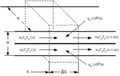
Considering the heat flows into and out of a control volume, marked by dotted lines, of thickness Δx and width W at a distance x from the entrance of the collector as shown in Figure 2.
Let the temperature of the air in the upper and lower ducts at a distance $x$ from the leading edge of the absorber plate is $T_{f_{u}}(x)$ and $T_{f_{l}}(x)$ respectively and at distance $(\mathrm{x}+\Delta \mathrm{x})$ is $T_{f_{u}}(x+\Delta x)$ and $T_{f_{l}}(x+\Delta x)$ respectively.
Figure 2. Energy balance of a control volume at a distance x from the entrance edge of the absorber plate
The energy balance of the control volume shown in Figure 2. for each air stream in upper and lower ducts inside the collector, respectively results
$m_{1} C_{p} T_{f_{u}}(x)+q_{u_{1}}(x) W \Delta x=m_{1} C_{p} T_{f_{u}}(x+\Delta x)$ (21)
$m_{2} C_{p} T_{f_{l}}(x)+q_{u_{2}}(x) W \Delta x=m_{2} C_{p} T_{f_{l}}(x+\Delta x)$ (22)
where, m1 and m2 are the mass flow rates of air in upper and lower ducts and Cp is the specific heat of air at constant pressure.
From Eqns. (21) and (22)
$\frac{T_{f_{u}}(x+\Delta x)-T_{f_{u}}(x)}{\Delta x}=\frac{W}{m_{1} C_{p}} q_{u_{1}}(x)$ (23)
$\frac{T_{f_{l}}(x+\Delta x)-T_{f_{l}}(x)}{\Delta x}=\frac{W}{m_{2} C_{p}} q_{u_{2}}(x)$ (24)
Taking Lt.Δx → 0, the above two equations are converted in to following linear differential equations
$m_{1} \frac{d T_{f_{u}}(x)}{d x}=\frac{W}{C_{p}} q_{u_{1}}(x)$, and (25)
$m_{2} \frac{d T_{f_{l}}(x)}{d x}=\frac{W}{C_{p}} q_{u_{2}}(x)$ (26)
After substituting values of $q_{u_{1}}$ and $q_{u_{2}}$ into the Eqns. (2) and (4) respectively and rearranging them, following expressions are obtained
$\left(h_{c, g-f_{u}}+h_{r, p-g}+U_{l}\right) T_{g}$$-h_{c, g-f_{u}} T_{f_{u}}-h_{r, p-g} T_{p}=S+U_{t} T_{a}$, (27)
$h_{c, g-f_{u}} T_{g}-\left(h_{c, g-f_{u}}+h_{c, p-f_{u}}+\frac{2 m_{1} C_{p}}{W L}\right) T_{f_{u}}$$+h_{c, p-f_{u}} T_{p}=-\frac{2 m_{1} C_{p}}{W L} T_{f_{u i}}$ (28)
$-h_{r, p-g} T_{g}-h_{c, p-f_{u}} T_{f_{u}}$$+\left(h_{c, p-f_{u}}+h_{c, p-f_{l}}+h_{r, p-g}+h_{r, p-b}\right) T_{p}$$-h_{c, p-f_{l}} T_{f_{l}}-h_{r, p-b} T_{b}=S$ (29)
$h_{c, p-f_{l}} T_{p}-\left(h_{c, p-f_{l}}+h_{c, b-f_{l}}+\frac{2 m_{2} C_{p}}{W L}\right) T_{f_{l}}$$+h_{c, b-f_{l}} T_{b}=-\frac{2 m_{2} C_{p}}{W L} T_{f_{l} i}$ (30)
$-h_{r, p-b} T_{p}-h_{c, b-f_{l}} T_{f_{l}}$$+\left(h_{r, p-b}+U_{b}+h_{c, b-f_{l}}\right) T_{b}=U_{b} T_{a}$ (31)
2.3 Evaluation of heat transfer coefficients
The radiative heat transfer coefficient between glass cover and sky, by considering sky as a black body, is given as;
$h_{r, g-s}=\frac{\sigma\left(T_{g}^{2}+T_{s}^{2}\right)\left(T_{g}+T_{s}\right)}{\left[\frac{1}{\varepsilon_{g}}-1\right]}$ (32)
where, the sky temperature Ts is given by [20].
Ts = 0.0552(Ta )1.5
And Convective heat transfer coefficient due to wind (for 0 ≤ Vw ≤ 5 m/s) is given by [20]
hw = 5.7 + 3.8 Vw (33)
The radiative heat transfer coefficient between glass cover and absorber plate hr,p-g evaluated [21, 22],
$h_{r, p-g}=\frac{\sigma\left(T_{p}^{2}+T_{g}^{2}\right)\left(T_{p}+T_{g}\right)}{\left[\frac{1}{\varepsilon_{p}}+\frac{1}{\varepsilon_{g}}-1\right]}$ (33)
The radiation heat transfer coefficient between absorber plate and back plate can be calculated using equation, given by [23, 24],
$h_{r, p-b}=\frac{\sigma\left(T_{p}^{2}+T_{b}^{2}\right)\left(T_{p}+T_{b}\right)}{\left[\frac{1}{\varepsilon_{p}}+\frac{1}{\varepsilon_{b}}-1\right]}$ (34)
The Convective heat transfer coefficient between glass cover and air flowing between glass cover and absorber plate is given by
$h_{c, g-f_{u}}=\frac{N u \times K_{a}}{D_{h}}$
where,
Nusselt number, Nu = 0.0158Re0.8 [25, 26]
Hydraulic diameter, $D_{h}=\frac{2 \times W \times H}{(W+H)}$
The Convective heat transfer coefficient between roughened absorber plate and air flowing in the upper duct is given by
$h_{c, p-f_{u}}=\frac{N u_{r} \times K_{a}}{D_{h}}$
where,
Nusselt number, Nur = 0.001047×Re1.3186×(e/d)0.3772×(α/90)-0.1198 [3]
Thermo-physical properties, i.e., dynamic viscosity (μ), specific heat (Cp) and thermal conductivity (k) of air were calculated using the following relations [27, 28].
Density $\rho_{a}=3.9147-0.016082 T_{f}$$+2.9013 \times 10^{-5} T_{f}^{2}-1.9407 \times 10^{-8} \times T_{f}^{3}$
Thermal conductivity $k_{a}$$=\left(0.0015215+0.097459 \times T_{f}-3.3322 \times 10^{-5} T_{f}^{2}\right) \times 10^{-3}$
Dynamic vis cosity, $\mu_{a}$$=\left(1.6157+0.06523 T_{f}-3.0297 \times 10^{-5} T_{f}^{2}\right) \times 10^{-6}$
The back loss coefficient (Ub) and side loss coefficient (Us) are respectively given by
$U_{b}=\frac{K_{i}}{\delta_{i}}$ and $U_{s}=\frac{(L+W) \delta_{i} k_{i}}{L W \delta_{i}}$
Correlation used for evaluation of top loss coefficient is given by Klein
${{U}_{t}}={{\left[ \frac{N}{{{\left\{ \frac{C}{{{T}_{p}}}\frac{({{T}_{p}}-{{T}_{a}})}{\begin{align} & N+(1+0.089{{h}_{w}}-0.1166{{h}_{w}}{{\varepsilon }_{p}}) \\ & (1+0.07866\times N) \\ \end{align}} \right\}}^{0.43(1-100/{{T}_{p}})}}}+\frac{1}{{{h}_{w}}} \right]}^{-1}}+K$
$K=\frac{\sigma ({{T}_{p,m}}+{{T}_{a}})(T_{p,m}^{2}+T_{a}^{2})}{\begin{align} & {{({{\varepsilon }_{p}}+0.0059{{h}_{w}}N)}^{-1}} \\ & +\frac{\begin{align} & 2N+(1+0.089{{h}_{w}}-0.1166{{h}_{w}}{{\varepsilon }_{p}}) \\ & \times (1+0.07866\times N)-1+0.133{{\varepsilon }_{p}} \\ \end{align}}{{{\varepsilon }_{g}}}-N \\ \end{align}}$
2.4 Thermal efficiency
Thermal efficiency of a solar air heater is defined as the ratio of useful energy gain to the incident solar energy on the absorber plate and is given by
$\eta_{t h}=\frac{Q_{u}}{S A_{p}}$ (35)
2.5 Thermohydraulic efficiency
The thermo-hydraulic efficiency represents the actual performance of a thermal system. It can be used to compare the performance of SAHs with various roughness arrangements to decide the best among these. The thermohydraulic efficiency or effective efficiency (ηeff) of solar air heater is defined as
$\eta_{e f f}=\frac{Q_{u}-P_{f a n}}{S A_{p}}$ (36)
where, Pfan is fan power required for forcing the air through duct, which is defined as
$P_{f a n}=\frac{m P_{\text {flow }}}{\eta_{f a n} \eta_{\text {motor }}}$ (37)
where, Pflow is flow pumping power, which is given as
$P_{\text {flow }}=\frac{m \Delta P}{\rho_{a}}$ (38)
where, ΔP is pressure drop given by
$\Delta P=\frac{f \rho_{a} L V^{2}}{2 D_{h}}$ (39)
Correlation for friction factor for arc shaped wire roughened absorber plate SAH is given as [29, 30]
fr = 0.14408 Re-0.17103 (e/d)0.1765 (α/90)0.1185 (40)
Friction factor for smooth duct is given as [3]
f = 0.059 Re-0.20
Overall pressure drop (ΔP) for double parallel flow solar air heater is
ΔP = ΔPu + ΔPl
where,
ΔPu = Pressure drop in upper duct, and,
ΔPl = Pressure drop in lower duct.
The list of fixed and variable parameters used in computation of the results, is given in Table 2. The value/range of roughness parameters has been selected on the basis of the previous work available in the literature.
Table 2. Typical values of operating and system parameters used in analytical study
|
System parameters |
Value |
|
Duct width, W |
0.3 m |
|
Collector tilt angle, β |
30o |
|
Relative roughness pitch, P/e |
12 |
|
Wind velocity, V |
1 m/s |
|
Number of glass covers (N) |
1 |
|
Thermal conductivity of insulation (ki), W/m K |
0.0262 W/m K |
|
Thickness of insulation, δi |
5 mm |
|
Transmittance–absorptance product, ταp |
0.85 |
|
Thermal conductivity of glass (kg), W/m K |
0.75 |
|
Emissivity of absorber plate (εP) |
0.9 |
|
Emissivity of bottom plate (εb) |
0.9 |
|
Emissivity of glass cover (εg) |
0.88 |
|
Thickness of glass cover (δg), m |
0.004 |
|
Operating Parameters |
Base Value |
Range Value |
|
Collector length, L |
1.5 m |
0.1 – 2.5 m |
|
Relative arc angle, α/90 |
0.33 |
0.33 ‒ 0.66 |
|
Duct depth (H), m |
0.03 |
0.01 – 0.2 |
|
Relative roughness height, e/d |
0.02 |
0.02 ‒ 0.06 |
|
Solar radiation intensity, S |
900 W/m2 |
500–1000 W/m2 |
|
Ambient temperature, Ta |
300 K |
300 - 330K |
|
Reynolds number, Re |
20000 |
1000 ‒ 40,000 |
From the solutions of Eqns. (1) – (5) we can find out the Tg, Tp, Tb, Tfu and Tfl. The direct solution of these equations are not possible because different convective and radiative heat transfer coefficients are functions of these temperatures. In view of this, iterative method has been employed to solve the Eqns. (1) – (5), to get the values of respective temperatures. The iterative method involves the repetitive calculation of a different temperatures and heat transfer coefficients till the new and also the preceding values are approximately equal or differ by 0.001℃. Within the iteration method, initial guessed values of Tg, Tp and Tb are used to calculate the convective and radiative heat transfer coefficients. The values of the calculated heat transfer coefficients are used to find out new values of glass cover temperature Tg, plate temperature Tp, back plate temperature Tb, and also the outlet air temperature Tfu and Tfl. The freshly calculated temperature values area unit compared with the initially assumed ones. The computer program in MATLAB, was developed to perform the iteration method to calculate unknowns.
4.1 Validation of the mathematical model
Validity of the mathematical model has been tested by comparison of present theoretical results with experimental results of Sahu and Prasad [9], who have investigated the performance of air flowing through bottom duct of SAH with arc shaped wire as roughness on the absorber plate of its back side. Figure 3 shows the trend of variation of thermal efficiency v/s Reynolds number for present model and that of Sahu and Prasad [9]. From Figure it is clear that results of present model is better as expected. The variations of thermal efficiency vs Reynolds number have similar nature as the results reported by Sahu and Prasad [31, 32] under similar geometrical and operating parameters, which show good agreement of the present mathematical model.
Figure 3. Variation of Reynolds number vs the thermal efficiency
The values of different performance parameters were calculated for the parallel flow solar air heater having arc shape wire roughened absorber plate have been calculated and discussed with reference to different plots given in the following sections.
5.1 Thermal efficiency variations
5.1.1 Thermal efficiency vs Reynolds number
The thermal efficiency of SAH has been calculated for various values of Reynolds numbers corresponding to mass flow rates (0.006-0.2 kg/s) for relative roughness height (e/d) of 0.02 - 0.06 and solar radiation intensity 1000 W/m2 and the variation has been shown in Figure 4. From the Figure this is clear that the thermal efficiency of the solar air heater increases as Reynolds number (or air mass flow rate) increases. This happens because the useful heat gain (Q = mcp(To - Ti)) increases as mass flow rate (m) increases. For greater values of Reynolds number, increase in thermal efficiency is very small because at higher Reynolds number, the heat transfer coefficient due to convection between the absorber plate and the air increases but temperature difference between absorber plate and air decreases. Thus combined effect of these two parameters (Convective heat transfer coefficient and temperature difference) finally results in marginal increase in thermal efficiency at higher Reynolds number (above Re = 20000).
Figure 4. Thermal efficiency vs Reynolds number variation
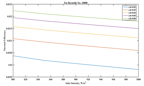
5.1.2 With insolation
Figure 5 shows the variation of thermal efficiency with the solar radiation intensity for several values of relative roughness height (e/d). It is observed that the thermal efficiency decreases slowly with increase in the insolation because with increase in insolation, absorber plate temperature increases, thus radiative heat loss from the collector also increases which results in low thermal efficiency.
Figure 5. Thermal efficiency as a function of solar radiation intensity
5.1.3 With duct depth (H)
The effect of duct depth on the thermal efficiency for several values of relative roughness height (e/d) like 0.02, 0.03 and 0.04 is shown in Figure 6. From this Figure it is clear that the thermal efficiency of roughened SAH decreases as the duct depth of the collector increases because mass velocity (G) of air passing through the duct decreases. From Figure this is also clear that for a fixed value of duct depth thermal efficiency increases as relative roughness height increases.
Figure 6. Thermal efficiency v/s duct depth
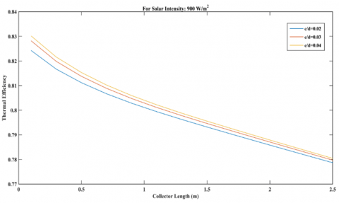
5.1.4 With collector length
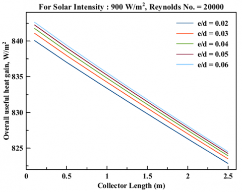
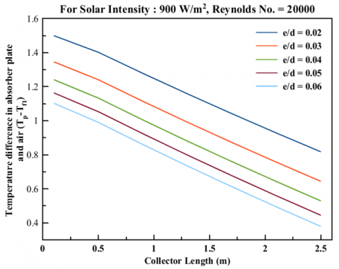
The plot of thermal efficiency v/s collector length for several relative roughness heights (e/d) for fixed value of Solar radiation intensity 900 W/m2 and Reynolds number 20000 has been shown in Figure 7. From the Figure this is clear that the thermal efficiency of the SAH decreases with increasing collector length. This is because the useful heat gain decreases as collector length increases due to decrease in temperature difference, between absorber plate and air passing through it i.e. (Tp - Tfu), and between glass cover and flowing air i.e. (Tg - Tfu) as shown in Figures 8, 9 & 10 respectively, while heat transfer coefficient due to convection, glass cover temperature absorber plate temperature, and outlet air temperature increase with increase in collector length.
Figure 7. Thermal efficiency v/s collector length [33, 34]
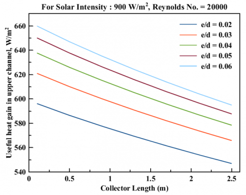
Figure 8. Useful heat gain from absorber plate by air passing through upper(roughened) and lower(smooth) duct v/s collector length
Figure 9. Overall useful heat gain by air passing through upper and lower duct
Figure 10. Temperature difference in absorber plate and air passing through upper duct and temperature difference in glass cover and air passing through upper duct v/s Reynolds number
5.2 Variation of useful heat gain by air
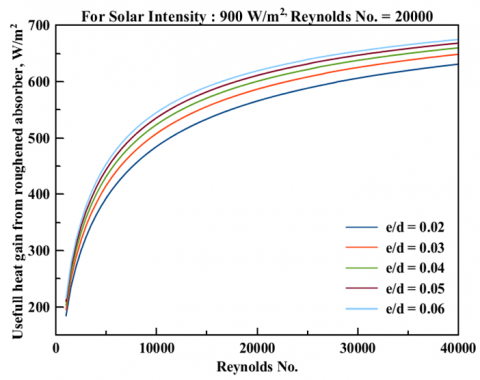
Figure 11. Useful heat gain from absorber plate by air passing through upper(roughened) and lower(smooth) duct v/s Reynolds number
Variation of useful heat gain by air v/s Reynolds number for relative roughness heights e/d = 0.02-0.06 and for insolation of 900 W/m2 is shown in Figure 11. From Figure it is clear that useful heat gain increases rapidly as Reynolds number increases in the range of 1000 to nearly 10000 and above 10000 Reynolds number, increase in useful heat gain is small because as the Reynolds number increases heat transfer coefficient due to convection also increases. But, as Reynolds number increases, absorber plate temperature decreases, so difference in absorber plate and air temperature decreases for higher Reynolds number. Thus combined effect of above two parameters results decrease in useful heat gain. From Figure this is also clear that for a given Reynolds number useful heat gain is higher for higher relative roughness height (i.e. e/d = 0.06) because convective heat transfer coefficient is higher for higher relative roughness height and radiative heat transfer coefficient is lower for higher relative roughness height so radiative heat exchange between absorber plate and glass cover is lower.
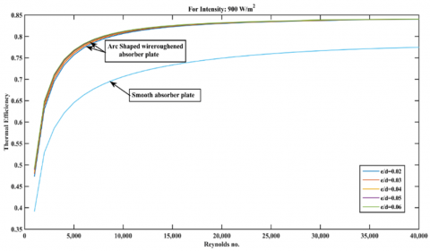
5.3 Comparison of thermal efficiencies
Figure 12 shows a comparison between thermal efficiencies of the parallel flow SAH having a absorber plate with arc shaped wire at its upper side and lower side smooth, and a parallel flow SAH with its absorber plate both sides smooth, operating under similar conditions [35, 36].
From Figure it is clear that the thermal efficiency of the parallel flow SAH with roughened absorber plate is about 8-10% more than parallel flow SAH with smooth absorber plate. This is because heat transfer coefficient between the roughened absorber plate and the air increases due to breakage of laminar sub-layer adjacent to the absorber surface at fluid flow side in the turbulent zone.
Figure 12. Thermal efficiency v/s Reynolds number
5.4 pressure drop variation
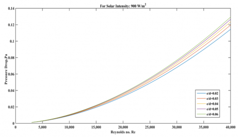
The friction factor, f, is a dimensionless quantity that mainly depends on the velocity of the fluid flow V, hydraulic diameter Dh, fluid density ρ, and dynamic viscosity of fluid μ. It's also a function of nature of the surface i.e. wall roughness which depends on the size, spacing and shape of the roughness elements. The pressure drop in the collector duct is evaluated by using the appropriate value of friction factor. In the present investigation, the values of friction factor have been calculated by using the correlation given in Eq. (40) and the pressure drop in the duct with one side artificially roughened by arc shaped wires and heated by insolation has been evaluated using Eq. (39).
The effect of pressure drop on the Reynolds number for relative roughness heights e/d = 0.02-0.06 has been presented in Figure 13. It is observed that pressure drop (ΔP) increases as Reynolds number increases because ΔP is directly proportional to square of average flow velocity, V i.e. variation of pressure drop with respect to flow velocity is parabolic, thus as average flow velocity or Reynolds number increases pressure drop increases at higher rate with respect to flow velocity. From figure it is also clear that variation of pressure drop for several values of relative roughness height (i.e. e/d = 0.02-0.06) is negligible for lower values of Reynolds number (i.e. Re < 20000 approx.). And for higher values of Reynolds number (i.e. Re > 20000) increase in pressure drop is comparatively higher and also change in pressure drop for several values of relative roughness height is significant.
Figure 13. Pressure drop v/s Reynolds number
5.5 Variation of pumping power
The effect of pumping power on the Reynolds number for relative roughness heights e/d = 0.02-0.06 has been presented in Figure 14. Pumping power is directly proportional to mass flow rate i.e. flow velocity and pressure drop but pressure drop (ΔP) is directly proportional to square of flow velocity. Thus pumping power is directly proportional to cube of flow velocity i.e. variation of pumping power with flow velocity is cubic. Therefore as flow velocity or mass flow rate increases, pumping power increases at higher rate than the average flow velocity. From Figure it is clear that pumping power also increases as relative roughness height increase and the rate of increase in pumping power becomes very small above relative roughness height 0.05.
Figure 14. Pumping power v/s Reynolds number
5.6 Variation of thermo hydraulic efficiency
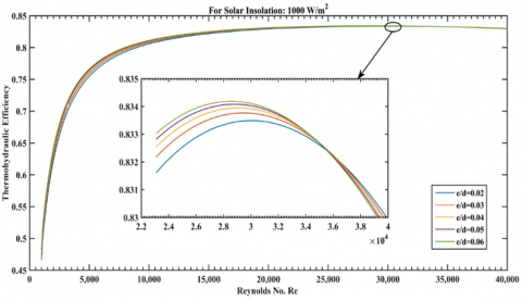
The thermo-hydraulic efficiency is such a parameter which is used to compare the performance of SAHs with different roughness arrangements (materials and geometries) to decide the best among these. The plot of thermo-hydraulic efficiency v/s Reynolds number for several values of relative roughness height (e/d) and for fixed values of other roughness parameters (α/90 = 0.45 & P/e = 12), has been shown in Figure 15.
From Figure this is clear that the maximum thermohydraulic or effective efficiency is obtained corresponding to e/d = 0.06 for a Re value of nearly 29,000, whereas the thermohydraulic efficiency is maximum corresponding to e/d = 0.02 for 30,000 < Re < 40000. For 1000 < Re < 8,000, increase in thermohydraulic efficiency is very sharp whereas above 8000 value of Re, increase in thermohydraulic efficiency is small. This is because at higher Reynolds number the pumping power needed to propel air through ducts increases sharply as the pumping power is directly proportional to cube of air velocity in the duct.
Figure 15. Thermo hydraulic efficiency v/s Reynolds number
5.7 Comparison of thermohydraulic efficiencies
Figure 16 shows a comparison of thermohydraulic efficiencies of the parallel flow SAH having roughened absorber plate and parallel flow SAH with smooth absorber plate under similar conditions of operation. For 1000 < Re < 29000 thermohydraulic efficiency is higher for parallel flow roughened SAH as compared to parallel flow smooth SAH.
Figure 16. Thermo hydraulic efficiency v/s Reynolds number for parallel flow roughened SAH and parallel flow conventional SAH (a) for Re = 1000-40000
It is also clear from the Figure that there is no effect of variation of several values of relative roughness heights (e/d) on thermohydraulic efficiency for nearly Re = 35,000, and above that the thermohydraulic efficiency becomes highest for lowest value of relative roughness height (i.e. e/d = 0.02). This is because, when Reynolds number increases above the 35,000, pumping power required to keep air passing through the duct with e/d = 0.06 becomes higher than the duct with e/d = 0.02. It can also be concluded that based on the thermohydraulic efficiency criteria parallel flow roughened SAH is not beneficial for higher Reynolds number i.e. Re > 29000.
5.8 Glass cover temperature variation
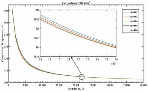
5.8.1 With Reynolds number
Variation of glass cover temperature with Reynolds number for relative roughness heights e/d = 0.02-0.06 and for a constant value of insolation is shown in the Figure 17. From Figure it is observed that glass cover temperature decreases sharply as Reynolds number increases from 1000 to nearly 8000 and beyond that decrease in glass cover temperature is very small. This happens due to the fact that as Reynolds number increases thermal boundary layer beneath the glass cover decreases. Thus, temperature gradient in perpendicular direction of glass cover increases hence convective heat transfer coefficient increases therefore more heat is transferred from glass cover to air passing through upper duct and hence temperature of glass cover decreases.
This is also seen that for a particular value of Re, glass cover temperature is greater for smaller value of relative roughness height (e/d = 0.02) because absorber plate temperature is greater for smaller value of e/d.
Figure 17. Variation of glass cover temperature vs Reynolds number
5.8.2 With collector length
Variation of mean glass cover temperature as collector length for relative roughness heights e/d = 0.02-0.06, solar radiation intensity of 900 W/m2 and Re = 20,000, is shown in the Figure 18. From Figure it is clear that glass cover temperature increases with collector length. Because as collector length increases absorber plate temperature increases, so more heat transfer due to radiation from absorber plate to glass cover takes place. Also in laminar flow thermal boundary layer thickness is directly proportional to square root of the collector length thus as collector length increases thermal boundary layer thickness increases. So temperature gradient in perpendicular direction of glass cover decreases therefore convective heat transfer coefficient decreases. Thus less heat is transferred from glass cover to air passing through upper duct, so absorber plate temperature increases. From Figure this is also clear that for a particular value of collector length, glass cover temperature is greater for smaller value of relative roughness height i.e. e/d = 0.02.
Figure 18. Variation of glass cover temperature vs collector length
5.9 Mean absorber plate temperature variation
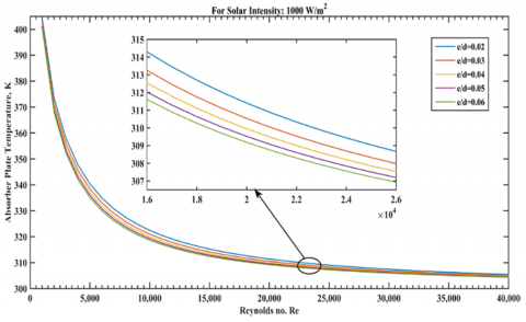
5.9.1 With Reynolds number
Variation of mean absorber plate temperature with Re for relative roughness heights e/d = 0.02-0.06 and Insolation of 1000 W/m2 is shown in the Figure 19. From Figure it is clear that mean absorber plate temperature decreases sharply for the smaller values of the Reynolds number (i.e. nearly Re = 1000-12,000) and above Re = 12,000 decrease in mean absorber plate temperature is very slow [37-39].
Because as Reynolds number increases, air flow changes from laminar to transition flow above the Reynolds number equal to nearly 2100. In transition flow mixing of air particles takes place due to turbulence created by random motion of air particles, so convective heat transfer coefficient increases rapidly in transition zone. And as Re increases thermal boundary layer thickness over and beneath the absorber plate decreases so temperature gradient in perpendicular direction of absorber plate increases thus convective heat transfer coefficient increases therefore more heat is transferred from absorber plate to air passing through upper and lower ducts hence temperature of mean absorber plate decreases.
Figure 19. Variation of absorber plate temperature v/s Reynolds number
From Figure this is also clear that for a given value of Reynolds number, absorber plate temperature is greater for smaller value of e/d (i.e. e/d = 0.02).
5.9.2 With Insolation
Variation of absorber plate with respect to solar intensity for relative roughness heights e/d = 0.02-0.06 and constant value of Re 20,000 and collector length 1.5 m is shown in the Figure 20. From Figure it is clear that absorber plate temperature increases as solar radiation intensity increases. Since input thermal energy from insolation increases the temperature. It is also seen that for a particular value of insolation absorber plate temperature is higher for smaller values of relative roughness height i.e. e/d = 0.02 because of lower heat transfer due to lower turbulence corresponding to this given Reynolds number.
Figure 20. Mean absorber plate temperature v/s solar radiation intensity
5.9.3 With collector length
Variation of temperature of absorber plate as collector length for relative roughness heights e/d = 0.02-0.06, solar radiation intensity 900 W/m2 and Re = 20,000, is shown in the Figure 21. From Figure it is clear that absorber plate temperature increases as collector length increases. Because in laminar flow thermal boundary layer thickness is directly proportional to square root of the collector length thus as collector length increases thermal boundary layer thickness increases. So temperature gradient in perpendicular direction of absorber plate decreases therefore convective heat transfer coefficient decreases. The heat transfer from absorber plate to air passing through upper and lower ducts is low and so temperature of absorber plate increases. From Figure this is also clear that for a particular value of collector length, absorber plate temperature is higher for smaller values of relative roughness height i.e. e/d = 0.02.
Figure 21. Absorber plate temperature v/s collector length
5.10 Back plate temperature variation
5.10.1 With Reynolds number
Variation of back plate temperature with respect to Reynolds number for relative roughness heights e/d = 0.02-0.06 and for 1000 W/m2 solar radiation intensity is shown in the Figure 22. From Figure it is clear that back plate temperature decreases sharply as Reynolds number increases from 1000 to nearly 8000 and above 8000 Reynolds number decrease in back plate temperature is small. As Reynolds number increases thermal boundary layer thickness over the back plate decreases so temperature gradient in perpendicular direction of back plate increases thus convective heat transfer coefficient increases. Therefore more heat is transferred from back plate to air passing through lower duct so temperature of back plate decreases. Also as the Reynolds number increases heat transfer due to radiation from absorber plate to back plate decreases because of decrease in temperature of absorber plate and heat transfer coefficient due to radiation between absorber plate and back plate.
From Figure this is also clear that for a given value of Reynolds number back plate temperature is higher for smaller value of relative roughness height i.e. e/d = 0.02 on the absorber plate. As absorber plate temperature is higher for smaller value of relative roughness height so radiation heat exchange between absorber plate and back plate is higher.
Figure 22. Absorber plate temperature v/s Reynolds number
5.11 Outlet air temperature variation
5.11.1 With Reynolds number
Variation of outlet air temperature as Reynolds number for relative roughness heights e/d = 0.02-0.06 and for constant value of solar radiation intensity 1000 W/m2 is shown in the Figures 23, 24 & 25. From Figs. it is clear that outlet air temperature decreases as Re increases. Because when Re increases flow changes from laminar to transition flow above the Reynolds number nearly 2100. In transition flow mixing of air particle takes place due to turbulence created by randomness in air flow so convective heat transfer coefficient increases rapidly in transition zone. And as Reynolds number increases thermal boundary layer thickness over the absorber and back plate decreases so temperature gradient in perpendicular direction of glass cover, absorber and back plate increases thus convective heat transfer coefficient increases therefore more heat is transferred from glass cover, absorber and back plate to air passing through upper and lower duct so temperature of air increases. From Figure this is also clear that for a given value of Re outlet air temperature is higher for higher e/d (e/d = 0.06), but for a given value of Reynolds number increase in outlet air temperature for e/d (e/d > 0.04) is very small.
Figure 23. Upper duct air outlet temperature v/s Reynolds number
Figure 24. Lower duct air outlet temperature v/s Reynolds number
Figure 25. Outlet air mean temperature v/s Reynolds Number
5.11.2 With solar insolation
Variation of outlet air temperature with respect to solar radiation intensity for relative roughness heights e/d = 0.02-0.06 and for Re = 20,000 and collector length of 1.5 m is shown in Figure 26. From this Figure it is clear that outlet air temperature increases as solar radiation intensity increases. It is also found that for a particular value of solar radiation intensity outlet air temperature is higher for higher relative roughness height i.e. e/d = 0.06, but for a particular value of Reynolds number increase in outlet air temperature for relative roughness height above 0.04 is small.
Figure 26. Air outlet temperature v/s solar radiation intensity
5.11.3 With collector length
Variation of outlet air temperature with respect to collector length for relative roughness heights e/d = 0.02-0.06 and for solar radiation intensity 900 W/m2 and Re 20,000 is shown in the Figure 27. From Figure it is clear that outlet air temperature increases as collector length increases. Because air flow changes from laminar to transition flow as collector length increases and convective heat transfer coefficient decreases as collector length increases in laminar flow due to decrease in temperature gradient in perpendicular direction of absorber plate. In transition zone convective heat transfer coefficient increases as collector length increases because of intense mixing of air particles due to turbulence created by zig-zag motion of air particles.
From Figure this is also clear that for a particular value of collector length outlet air temperature is higher for higher relative roughness height i.e. e/d = 0.06, but for a particular value of collector length increase in outlet air temperature for relative roughness height (e/d) above 0.04 is very small.
Figure 27. Outlet air temperature v/s collector length
5.12 Convective heat transfer coefficient variation
5.12.1 With Reynolds number
Variation of convective heat transfer coefficient as Reynolds number for relative roughness heights e/d = 0.02-0.06for solar radiation intensity 900 W/m2 is shown in the Figure 28. From Figure it is clear that convective heat transfer coefficient increases as Reynolds number increases because as Re increases thickness of thermal boundary layer decreases so temperature gradient in perpendicular direction of the absorber plate increases. From Figure this is also clear that for a given value of Reynolds number, convective heat transfer coefficient is higher for higher relative roughness height i.e. e/d = 0.06 because in this case the flow separation is delayed due to higher turbulence and for a particular value of Reynolds number increase in convective heat transfer coefficient for relative roughness height (e/d) above 0.04 decreases.
Figure 28. Convective heat transfer coefficient between roughened absorber plate and air v/s Reynolds number
5.12.2 With collector length
Figure 29. Convective heat transfer coefficient between roughened absorber plate and air v/s Reynolds number
Variation of convective heat transfer coefficient with respect to collector length for relative roughness heights e/d = 0.02-0.06for fixed value of Insolation and Reynolds number 20000 is shown in the Figures 29 & 30. From Figs. it is clear that convective heat transfer coefficient first decreases up-to 0.3 m length of the collector and then increases as collector length increases. This happens because, air flow is laminar up-to collector length equal to 0.3 m, and above collector length of 0.3 m air flow starts to change in transition flow. And in transition flow mixing of air particles stats thus causing turbulence hence increase in convective heat transfer coefficient.
Figure 30. Convective heat transfer coefficient between smooth plate and air v/s Reynolds number
5.13 Radiative heat transfer coefficient variation
5.13.1 With Reynolds number
Figure 31. Heat transfer coefficient due to radiation, between roughened absorber plate and glass cover, v/s Reynolds number
Figure 32. Heat transfer coefficient due to Radiation, between absorber plate and back plate, v/s Reynolds number
Variation of radiative heat transfer coefficient with respect to Reynolds number for relative roughness heights e/d = 0.02-0.06 and for solar radiation intensity 1000 W/m2 is shown in the Figures 31 & 32. From Figure it is clear that radiative heat transfer coefficient decreases as Reynolds number increases. This happens because as the Reynolds number increases temperature of absorber plate decreases. From Figure this is also clear that for a particular value of Reynolds number radiative heat transfer coefficient is higher for smaller values of relative roughness height i.e. e/d = 0.02 because absorber plate temperature is higher for smaller values of relative roughness height i.e. e/d = 0.02.
5.13.2 With collector length
Variation of radiative heat transfer coefficient with respect to collector length for relative roughness heights e/d = 0.02-0.06, solar radiation intensity of 900 W/m2 and Re of 20000 is shown in the Figure 33. From Figure it is clear that radiative heat transfer coefficient increases with collector length because as collector length increases absorber plate temperature increases.
Figure 33. Radiative heat transfer coefficient between upper and lower duct v/s collector length
This work presents an analytical study for predicting the thermal performance of a double-parallel flow solar air heater. The absorber plate, placed between the glass cover and back plate is artificially roughened with arc shaped wires at its upper side. Effects of the Reynolds number (or mass flow rate), duct depth, collector length, insolation, temperature of inlet air and roughness parameters on thermal efficiency, thermohydraulic efficiency and pumping power have been investigated. Based on the results the following conclusions are drawn:
Scope of Future Work
The theoretical model can be verified by conducting actual experiments.
|
Ap |
Surface area of absorber plate (m2) |
|
H |
Height of duct (m) |
|
W |
Width of duct (m) |
|
L |
Length of test section in duct (m) |
|
Dh |
Hydraulic diameter (m) |
|
e |
Roughness height (m) |
|
e/d |
Relative roughness height |
|
P |
Roughness Pitch (m) |
|
P/e |
Relative roughness pitch |
|
FR |
Collector heat removal factor |
|
f |
Friction factor for roughened duct |
|
Ut |
Top loss coefficient (W/m2 K) |
|
Ub |
Back loss coefficient (W/m2 K) |
|
To |
Air outlet temperature (K) |
|
Ti |
Air inlet temperature (K) |
|
Tg |
Glass cover temperature, k |
|
Ta |
Ambient temperature, K |
|
$h_{r, g-s}$ |
Radiative heat transfer coefficient between Glass cover and sky, W/m2 K |
|
$h_{r, p-b}$ |
Radiative heat transfer coefficient between Absorber plate and bottom plate, W/m2 K |
|
$h_{c, p-f_{u}}$ |
Convective heat transfer coefficient between absorber plate and air flowing in upper channel, W/m2 K |
|
$h_{c, b-f_{l}}$ |
Convective heat transfer coefficient between bottom plate and air flowing in lower channel, W/m2 K |
|
$\dot{m}$ |
Mass flow rate of air (kg/s) |
|
ΔT |
Air temperature rise across the duct (℃) |
|
k |
Thermal conductivity (W/m K) |
|
CP |
Specific heat of air (J/kg K) |
|
Pm |
Pumping power (W) |
|
Re |
Reynolds number |
|
S |
Intensity of solar radiations (W/m2) |
|
V |
Air mean flow velocity in duct (m/s) |
|
Nu |
Nusselt number |
|
qu |
Useful heat gain (W) |
|
h |
Heat transfer coefficient (W/m2 K) |
|
Us |
Side loss coefficient (W/m2 K) |
|
Ul |
Overall heat loss coefficient (W/m2 K) |
|
Tp |
Average temperature of absorber plate (K) |
|
Tf |
Average temperature of air (K) |
|
Ts |
Sky temperature, K |
|
Tb |
Mean bottom plate temperature, K |
|
$h_{r, p-g}$ |
Radiative heat transfer coefficient between absorber plate and glass cover, W/m2 K |
|
$h_{c, g-f_{u}}$ |
Convective heat transfer coefficient between glass cover and air flowing in upper channel, W/m2 K |
|
$h_{c, p-f_{l}}$ |
Convective heat transfer coefficient between absorber plate and air flowing in lower channel, W/m2 K |
|
SAH |
Solar Air Heater |
|
Greek symbols |
|
|
δi |
Thickness of insulation (m) |
|
εp |
Emissivity of absorber plate |
|
εg |
Emissivity of glass cover |
|
εb |
Emissivity of back plate |
|
α |
Arc angle (o) |
|
ηm |
Motor efficiency |
|
τ |
Transmissivity of glass cover |
|
ηth |
Thermal efficiency of solar air heater |
|
ταp |
Transmissivity–absorptivity product of glass cover |
|
μ |
Dynamic viscosity of air, N-s/m2 |
|
αp |
Absorptivity of absorber plate |
|
β |
Tilt angle of collector surface, degree |
|
α |
Angle of attack, degree |
|
ρ |
Air density (kg/m3) |
|
ηf |
Fan efficiency |
|
ƞeff |
Effective or Thermohydraulic efficiency |
[1] Suman, S., Khan, M.K., Pathak, M. (2015). Performance enhancement of solar collectors—A review. Renewable and Sustainable Energy Reviews, 49: 192-210. https://doi.org/10.1016/j.rser.2015.04.087
[2] Saini, R.P., Singal, S.K. (2007). A review on roughness geometry used in solar air heaters. Solar Energy, 81(11): 1340-1350. https://doi.org/10.1016/j.solener.2007.01.017
[3] Saini, S.K., Saini, R.P. (2008). Development of correlations for Nusselt number and friction factor for solar air heater with roughened duct having arc-shaped wire as artificial roughness. Solar Energy, 82(12): 1118-1130. https://doi.org/10.1016/j.solener.2008.05.010
[4] Ozgen, F., Esen, M., Esen, H. (2009). Experimental investigation of thermal performance of a double-flow solar air heater having aluminium cans. Renewable Energy, 34(11): 2391-2398. https://doi.org/10.1016/j.renene.2009.03.029
[5] Prasad, B.N., Saini, J.S. (1988). Effect of artificial roughness on heat transfer and friction factor in a solar air heater. Solar Energy, 41(6): 555-560. https://doi.org/10.1016/0038-092X(88)90058-8
[6] Hernandez, A.L., Quiñonez, J.E. (2013). Analytical models of thermal performance of solar air heaters of double-parallel flow and double-pass counter flow. Renewable Energy, 55: 380-391. https://doi.org/10.1016/j.renene.2012.12.050
[7] Yadav, S., Kaushal, M. (2014). Exergetic performance evaluation of solar air heater having arc shape oriented protrusions as roughness element. Solar Energy, 105: 181-189. https://doi.org/10.1016/j.solener.2014.04.001
[8] Gill, R.S., Hans, V.S., Saini, J.S. (2015). Heat transfer and friction characteristics of solar air heater duct roughened by broken arc shaped ribs combined with staggered rib piece. International Journal of Engineering Research Technology, 4: 2278-2281.
[9] Sahu, M.K., Prasad, R.K. (2017). Thermohydraulic performance analysis of an arc shape wire roughened solar air heater. Renewable Energy, 108: 598-614. https://doi.org/10.1016/j.renene.2017.02.075
[10] Gabhane, M.G., Kanase-Patil, A.B. (2017). Experimental analysis of double flow solar air heater with multiple C shape roughness. Solar Energy, 155: 1411-1416. https://doi.org/10.1016/j.solener.2017.07.038
[11] Gupta, D., Solanki, S.C., Saini, J.S. (1997). Thermohydraulic performance of solar air heaters with roughened absorber plates. Solar Energy, 61(1): 33-42. https://doi.org/10.1016/S0038-092X(97)00005-4
[12] Verma, S.K., Prasad, B.N. (2000). Investigation for the optimal thermohydraulic performance of artificially roughened solar air heaters. Renewable Energy, 20(1): 19-36. https://doi.org/10.1016/S0960-1481(99)00081-6
[13] Momin, A.M.E., Saini, J.S., Solanki, S.C. (2002). Heat transfer and friction in solar air heater duct with V-shaped rib roughness on absorber plate. International Journal of Heat and Mass Transfer, 45(16): 3383-3396. https://doi.org/10.1016/S0017-9310(02)00046-7
[14] Ho, C.D., Yeh, H.M., Wang, R.C. (2005). Heat-transfer enhancement in double-pass flat-plate solar air heaters with recycle. Energy, 30(15): 2796-2817. https://doi.org/10.1016/j.energy.2005.01.006
[15] Karmare, S.V., Tikekar, A.N. (2007). Heat transfer and friction factor correlation for artificially roughened duct with metal grit ribs. International Journal of Heat and Mass Transfer, 50(21-22): 4342-4351. https://doi.org/10.1016/j.ijheatmasstransfer.2007.01.065
[16] Aharwal, K.R., Gandhi, B.K., Saini, J.S. (2008). Experimental investigation on heat-transfer enhancement due to a gap in an inclined continuous rib arrangement in a rectangular duct of solar air heater. Renewable Energy, 33(4): 585-596. https://doi.org/10.1016/j.renene.2007.03.023
[17] Gupta, M.K., Kaushik, S.C. (2009). Performance evaluation of solar air heater having expanded metal mesh as artificial roughness on absorber plate. International Journal of Thermal Sciences, 48(5): 1007-1016. https://doi.org/10.1016/j.ijthermalsci.2008.08.011
[18] Hans, V.S., Saini, R.P., Saini, J.S. (2010). Heat transfer and friction factor correlations for a solar air heater duct roughened artificially with multiple v-ribs. Solar Energy, 84(6): 898-911. https://doi.org/10.1016/j.solener.2010.02.004
[19] Bhushan, B., Singh, R. (2012). Thermal and thermohydraulic performance of roughened solar air heater having protruded absorber plate. Solar Energy, 86(11): 3388-3396. https://doi.org/10.1016/j.solener.2012.09.004
[20] Duffie, J.A., Beckman, W.A. (2013). Solar Engineering of Thermal Processes. John Wiley Sons.
[21] Kumar, A., Saini, R.P., Saini, J.S. (2012). Heat and fluid flow characteristics of roughened solar air heater ducts–A review. Renewable Energy, 47: 77-94. https://doi.org/10.1016/j.renene.2012.04.001
[22] El-Sebaii, A.A., Aboul-Enein, S., Ramadan, M.R.I., Shalaby, S.M., Moharram, B.M. (2011). Investigation of thermal performance of-double pass-flat and v-corrugated plate solar air heaters. Energy, 36(2): 1076-1086. https://doi.org/10.1016/j.energy.2010.11.042
[23] Jaurker, A.R., Saini, J.S., Gandhi, B.K. (2006). Heat transfer and friction characteristics of rectangular solar air heater duct using rib-grooved artificial roughness. Solar Energy, 80(8): 895-907. https://doi.org/10.1016/j.solener.2005.08.006
[24] Behura, A.K., Prasad, B.N., Prasad, L. (2016). Heat transfer, friction factor and thermal performance of three sides artificially roughened solar air heaters. Solar Energy, 130: 46-59. https://doi.org/10.1016/j.solener.2016.02.006
[25] Ramani, B.M., Gupta, A., Kumar, R. (2010). Performance of a double pass solar air collector. Solar Energy, 84(11): 1929-1937. https://doi.org/10.1016/j.solener.2010.07.007
[26] Thombre, G.N., Lawankar, S.M. (2017). Review on Thermo-hydraulic Performance of Solar Air Heater having Artificial Roughness on Absorber Plate.
[27] Esen, H. (2008). Experimental energy and exergy analysis of a double-flow solar air heater having different obstacles on absorber plates. Building and Environment, 43(6): 1046-1054. https://doi.org/10.1016/j.buildenv.2007.02.016
[28] Yeh, H.M., Ho, C.D., Hou, J.Z. (2002). Collector efficiency of double-flow solar air heaters with fins attached. Energy, 27(8): 715-727. https://doi.org/10.1016/S0360-5442(02)00010-5
[29] Hedayatizadeh, M., Ajabshirchi, Y., Sarhaddi, F., Farahat, S., Safavinejad, A., Chaji, H. (2012). Analysis of exergy and parametric study of a v-corrugated solar air heater. Heat and Mass Transfer, 48(7): 1089-1101. https://doi.org/10.1007/s00231-011-0957-7
[30] Karim, M.A., Perez, E., Amin, Z.M. (2014). Mathematical modelling of counter flow v-grove solar air collector. Renewable Energy, 67: 192-201. https://doi.org/10.1016/j.renene.2013.11.027
[31] El-Khawajah, M.F., Aldabbagh, L.B.Y., Egelioglu, F. (2011). The effect of using transverse fins on a double pass flow solar air heater using wire mesh as an absorber. Solar Energy, 85(7): 1479-1487. https://doi.org/10.1016/j.solener.2011.04.004
[32] Dhiman, P., Thakur, N.S., Kumar, A., Singh, S. (2011). An analytical model to predict the thermal performance of a novel parallel flow packed bed solar air heater. Applied Energy, 88(6): 2157-2167. https://doi.org/10.1016/j.apenergy.2010.12.033
[33] Tchinda, R. (2009). A review of the mathematical models for predicting solar air heaters systems. Renewable and Sustainable Energy Reviews, 13(8): 1734-1759. https://doi.org/10.1016/j.rser.2009.01.008
[34] Sethi, M., Thakur, N.S. (2012). Correlations for solar air heater duct with dimpled shape roughness elements on absorber plate. Solar Energy, 86(9): 2852-2861. https://doi.org/10.1016/j.solener.2012.06.024
[35] Bopche, S.B., Tandale, M.S. (2009). Experimental investigations on heat transfer and frictional characteristics of a turbulator roughened solar air heater duct. International Journal of Heat and Mass Transfer, 52(11-12): 2834-2848. https://doi.org/10.1016/j.ijheatmasstransfer.2008.09.039
[36] Sharma, S.P., Saha, S.N. (2017). Thermohydraulic performance of double flow solar air heater with corrugated absorber. World Academy of Science, Engineering and Technology, International Journal of Energy and Power Engineering, 11(7): 855-861.
[37] Saha, S.N., Sharma, S.P. (2017). Energy and exergy analysis of double flow corrugated absorber solar air heaters. International Energy Journal, 17(4): 71-184.
[38] Chamoli, S., Chauhan, R., Thakur, N.S., Saini, J.S. (2012). A review of the performance of double pass solar air heater. Renewable and Sustainable Energy Reviews, 16(1): 481-492. https://doi.org/10.1016/j.rser.2011.08.012
[39] Hans, V.S., Saini, R.P., Saini, J.S. (2009). Performance of artificially roughened solar air heaters—A review. Renewable and Sustainable Energy Reviews, 13(8): 1854-1869. https://doi.org/10.1016/j.rser.2009.01.030