Saad Najeeb Shehab![]()
© 2023 IIETA. This article is published by IIETA and is licensed under the CC BY 4.0 license (http://creativecommons.org/licenses/by/4.0/).
OPEN ACCESS
An experimental analysis of the heat performance and characteristics for natural convective from the different types of heat sinks to surroundings are reported. This research examines three various configurations of heat sinks namely, with solid fins, with single rectangular notched fins and with double rectangular notched fins. The impact of fins spacing, percentage of removal (notched) area and electrical power inputs with constant the aspect ratio for height to length of fin on heat convective performance and increased rate of heat transfer are analyzed and discussed. The current results appear the thermal performance for a double notched fin heat sink as average Nusselt number about 20% bigger than single notched fins heat sink and about 38% bigger than solid fins heat sink for same case of heat sink. Finally, the results have been compared than last experimental work, a good convergence are appeared.
double notched, single notched, natural convective, heat sink, performance analysis
Notched heat sink considers one of most common configurations of heat sinks widely utilized in the manufacturing processes. This heat sink consists of fins array on the base plate with different fin spaces, fin heights and fin shapes. Many approaches of fin shape modification like perforation, notches which effect on the performance of convection heat. Heat sink is utilized to improvement heat performance and decreases the power consumption of systems. Many engineering and industrial applications of heat sink such as cooling of power supplies of computer and electronic equipment, electrical motors, heat exchangers, electrical transformers, thermal systems, condensers and radiators [1-3].
Barhatte et al. [4] studied numerically and experimentally the free heat convective from the solid and vertical notched rectangular fin arrays. They utilized the Fluent software (version 6.3) to a numerical simulate. They illustrated best convergence between the experimental and numerical results and data. Dixit et al. [5] studied the enhancement of natural heat convective from a heated finned base in horizontal position without notches and with notches. Thermal performance in terms of convective heat transfer coefficient for notched heat sink gives approximately between (30%) and (50%) bigger than without notches heat sink. Wange and Metkar [6] achieved a numerical and experimental investigate for free convective from an inverted notches heat sink utilizing ANSYS-Fluent (version 12) to a numerical analysis. They noted the strong effect of inverted notch fins on the characteristics of natural convective and the rate of heat transfer. Ahmadi et al. [7] present a numerical and experimental investigations for steady-state external free heat convective from an interrupted rectangular vertical fin. They used the Fluent software to simulate two dimensional models for study the influence of fin interruption. They machined and tested twelve various aluminum heat sinks with different geometrical (fins spacing and fin interruptions) to verify the numerical results. They showed that the adding interruptions enhances the heat performance. They concluded a new empirical correlation to compute the best interruption length as well as the obtained results can be utilized to enhance the natural convective from enclosure for different electronics and applications of power electronics. Pankaj et al. [8] investigated the steady state natural heat convection from a solid fins and perforated fins. They studied different variables of the heat sink geometry and heat convection. They noted that the rate of heat transfer for perforated fins with a constant pitch, 10 mm fin spacing, perforated diameter of 4 mm with a perforation geometry of 45 degree is best rectangular fins heat sink. Anish and Kanimozhi [9] investigated experimentally the mixed convection heat transfer improvement utilizing fin arrays with different notches shapes. They used rectangular fins type with two various notches like, triangular and circular, plus fin arrays without notches into a horizontal rectangular channel at a wide ranges of modified Rayleigh number and several flow rates. They concluded the fins geometry is the key factor in the fins array and they found that the circular notches fin arrays give more performance than that triangular notches fins. Dingare et al. [10] presented a numerical and experimental work of the free convective from a rectangular and pin fins heat sinks. They studied different parameters such as, spacing, surfaces temperatures, height of fin, diameter of pin fin, pin fins number and positions of pin fins. They generated the results in form of variation in average and base heat transfer coefficient and average and base Nusselt number and they concluded a correlation to compute a Nusselt number as function of Rayleigh Number. Kaladgia et al. [11] studied numerically the enhancement of heat transfer rate for rectangular fins with a circular perforation using ANSYS Fluent code. They analyzed the temperatures decreasing from a different of the circular shape perforations. Also, they studied the effect of wall heat flux and heat gradient on the perforated rectangular fins. They observed a great drop in temperatures plus, an enhancement in rate of heat transfer. They concluded the obtained results and data can be utilized to design the rectangular fins heat exchangers. Deshpandi et al. [12] presented an experimental study of mixed heat convection for heat transfer rate performance from a horizontal rectangular fin. They used heat sink with fin spacing between 2 mm and 14 mm, width to height of fin ratio about 3 and the length to height of fin ratio about 5 for power inputs between 25 W and 100 W. They observed that the fins with central notches and perforations (in triangular distribution) giving an enhancement in Nusselt number nearly with 41% than solid fins case. They developed an empirical correlation of dimensionless coefficient for convective heat transfer, flow of air and the geometrical variables. Other researchers presented a review of numerical and experimental enhancement for convection heat transfer using different configurations of fins [13-16].
The objectives of current investigation are to introduce an experimental analysis and compare the free heat convective improvement in a new design and configuration of heat sink using double rectangular notched fins with single notched fins and solid fin heat sinks. Various spacing with constant of height to length fin aspect ratio, different removal area percentage and various power inputs.
2.1 Experimental setup
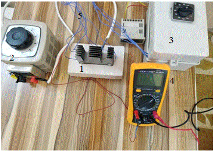
The experimental setup shown in Figure 1 consists of heat sink, sheet electrical heater, thermostone block, voltage of regulator to govern the power input as well as measurement devices namely, digital multi meter to read the voltage, current and ambient temperature, selector switch with reader of temperature to read surface temperatures and thermocouples wires. The heat sink consists of bright aluminum fin plates and spacers, the bright aluminum used to minimize the loss of radiation heat. Three types of fin plates are manufactures namely, solid, single rectangular notched and double rectangular notched. Basic dimensions of the heat sink utilized for the tests are length of (L= 100 mm), width of (B= 33.5 mm) and height of (H= 60 mm). It's heated from an under surface by three cartridge electrical heaters of (150 Watt). The dimensions of fins are length of 100 mm, height of 60 mm and thickness of 0.5 mm. In single notched heat sinks models, the notched length is fixed (LN= 80 mm) with different notched heights (HN= 7.5, 15, 22.5 and 30 mm) while, in double notched heat sink, LN= 24 mm, HN= 50 mm and L1= 32 mm as illustrated in Figure 2. The heat sink is formed using fin plates and spacer plates and jointed using bolts. The fin plates are segregated using different spacer plates. The assembly of heat sink is mounted into thermostone’s block with dimensions (in millimeters) of (160 length × 90 width × 50 thickness) and has low thermal conductivity (kt= 0.10 W/m.K) to decrease the heat conduction losses. The assembly of heat sink can be changed using a spacer. Spacers are utilized of thickness 0.5 mm and 1.0 mm. Three bores are drilled to insert 10 mm diameter cartridge electrical heaters and another two holes are drilled to insert 4 mm bolts.
The setup is placed in the suitable room to achieve the natural convective condition. Six calibrated thermocouples K-type are utilized to register the temperatures for different locations on the heat sink (fin plates and channel base) as well as the same type of thermocouple is utilized to register the temperature of ambient air.
(a) Whole setup
(b) Double rectangular notched heat sink
1. Heat sink assembly; 2. Voltage regulator; 3. Selector switch; 4. Multi meter; 5. Thermocouple wires; 6. Double rectangular notched heat sink; 7. Thermostone block
Figure 1. Experimental setup
(a) (b) (c)
(a) solid; (b) single rectangular notched; (c) double rectangular notched
Figure 2. Configurations of fins used in heat sinks
2.2 Experimental procedures and data modeling
Three different models of heat sinks contain solid fins, single rectangular notched fins and double rectangular notched fins are utilized. Five various of fins number namely, 3, 5, 7, 9 and 11 in the solid fins heat sink model are utilized. In another models (single rectangular notched fins and double rectangular notched fins heat sinks), four different percentage removal area like, 10%, 20%, 30% and 40% with 7 fins are used as illustrated in Table 1.
The heat sink dimensions are 100 mm in length and width of 33.5 mm. The dimensions of fins (fin length= 100 mm, fin height= 60 mm, the aspect ratio is fixed at HF/LF= 0.6). and the fin thickness= 0.5 mm) in all models used.
Four levels of power inputs (Qinp) namely, 10, 20, 30 and 40 Watt are utilized. The wall temperatures are registered utilizing six calibrated thermocouples and anther one thermocouple to read ambient air temperature. All readings of thermocouples are registered at time interval 30 minutes (when the maximum of two readings for temperatures changed about 0.5℃) up to steady state condition and then, the surface temperatures, ambient temperature, AC-current and voltage are recorded. The natural heat convective (Qconv) can be evaluated as follows [17, 18]:
$Q_{\text {conv }}=Q_{\text {inp }}-\left(Q_{\text {cond }}+Q_{\text {rad }}\right)$ (1)
The power input (Qinp) is computed as:
$\mathrm{Q}_{\mathrm{inp}}=\mathrm{IV}$ (2)
The conduction heat transfer (Qcond) is computed as follows [17]:
$\mathrm{Q}_{\text {cond }}=\frac{\mathrm{kA}_{\mathrm{S}}}{\mathrm{X}} \Delta \mathrm{T}$ (3)
The rate of radiation heat transfer (Qrad) is [17]:
$\mathrm{Q}_{\mathrm{rad}}=\mathrm{F}_{\mathrm{g}} \varepsilon \sigma \mathrm{A}_{\mathrm{S}}\left(\mathrm{T}_{\text {Sav }}^4-\mathrm{T}_{\mathrm{A}}^4\right)$ (4)
The heat losses by conduction and radiation from heat sink are very small because the low conductivity of thermostone (kt=0.10 W/m. K) utilized under the heat sink and also, using bright aluminum with low emissivity (ε=0.04) in manufacturing the heat sink then, can be neglected.
$\mathrm{Q}_{\mathrm{conv}}=\mathrm{Q}_{\mathrm{inp}}=\mathrm{IV}$ (5)
Also, the natural convective (Qconv) from the heat sink can be computed as the researches [19, 20]:
$\mathrm{Q}_{\mathrm{conv}}=\mathrm{h}_{\mathrm{av}} \mathrm{A}_{\mathrm{S}}\left(\mathrm{T}_{\text {sav }}-\mathrm{T}_{\infty}\right)$ (6)
From Eqns. (5) and (6), the average convection heat transfer coefficient (hav) is the researches [19, 20]:
$\mathrm{h}_{\mathrm{av}}=\frac{\mathrm{Q}_{\mathrm{inp}}}{\mathrm{A}_{\mathrm{S}}\left(\mathrm{T}_{\mathrm{sav}}-\mathrm{T}_{\infty}\right)}$ (7)
where,
Tsav is the average surface temperature and computed as:
$\mathrm{T}_{\mathrm{sav}}=\frac{\sum_{\mathrm{i}=1}^{\mathrm{n}} \mathrm{T}_{\mathrm{si}}}{\mathrm{n}}$ (8)
AS is the heat transfer surface area and computed as:
$\mathrm{A}_{\mathrm{S}}=(\mathrm{N}-1) \mathrm{S} \mathrm{L}_{\mathrm{F}}+2 \mathrm{NH}_{\mathrm{F}} \mathrm{L}_{\mathrm{F}}$ (9)
$A_S=(N-1) S L_F+2 N\left(A_F-A_N\right)$ (10)
$A_S=(N-1) S L_F+2 N\left(A_F-2 A_N\right)$ (11)
AF and AN are the fin area and notched area respectively, and calculated as:
$A_F=L_F H_F$ (12)
$\mathrm{A}_{\mathrm{N}}=\mathrm{L}_{\mathrm{N}} \mathrm{H}_{\mathrm{N}}$ (13)
The area removal percentage from fin (%AR) is:
$\% A_R=\frac{A_N}{A_F} \times 100$ (14)
The spacing (S) is calculated as:
$S=\frac{B-(N t)}{N-1}$ (15)
The average Nusselt number (Nuav) can be computed as the researches [19, 20]:
$\mathrm{Nu}_{\mathrm{av}}=\frac{\mathrm{h}_{\mathrm{av}} \mathrm{S}}{\mathrm{k}_{\mathrm{a}}}$ (16)
Table 1. Models of heat sinks
|
Fins configurations |
Notched area, AN (mm2) |
Area removal percentage, %AR |
Fins number N |
Fins spacing S (mm) |
|
Solid (without notches) |
0 |
0 |
3 5 7 9 11 |
16 7.75 5 3.625 2.8 |
|
Single rectangular notched |
600 1200 1800 2400 |
10 20 30 40 |
7 |
5 |
|
Double rectangular notched |
2400 |
10 20 30 40 |
7 |
5 |
In general, the uncertainties due to from readings, measurements, calibrations and instruments kinds. To evaluate these uncertainties, the analytical approach can be used. The average Nusselt number (Nuav) is a function of three independent variables namely, voltage (V), AC-current (I) and temperature difference ($\Delta \mathrm{T}=\mathrm{T}_{\mathrm{sav}}-\mathrm{T}_{\infty}$). Then, the uncertainties in values of average Nusselt number (ENuav) can be calculated as follows [18, 19]:
$\begin{gathered}\mathrm{E}_{\mathrm{Nu}_{\mathrm{av}}}=\pm\left\lceil\left(\frac{\partial \mathrm{Nu}_{a v}}{\partial \mathrm{V}} \mathrm{E}_{\mathrm{V}}\right)^2+\left(\frac{\partial \mathrm{Nu}_{a v}}{\partial \mathrm{I}} \mathrm{E}_{\mathrm{I}}\right)^2\right. \\ \left.+\left(\frac{\partial \mathrm{Nu}_{a v}}{\partial \Delta \mathrm{T}} \mathrm{E}_{\Delta \mathrm{T}}\right)^2\right]^{1 / 2}\end{gathered}$ (17)
where,
$\mathrm{E}_{\mathrm{V}}=\pm 0.05$ (error of voltage), $\mathrm{E}_{\mathrm{I}}=\pm 0.005$ (error of $\mathrm{AC}$ current) and $\mathrm{E}_{\Delta \mathrm{T}}=\pm 0.01$ (temperature difference error).
$\left(\frac{\partial \mathrm{Nu}_{a v}}{\partial \mathrm{V}}\right)=\frac{\mathrm{IS}}{\mathrm{A}_{\mathrm{S}} \Delta \mathrm{T} \mathrm{k}}$ (18)
$\left(\frac{\partial \mathrm{Nu}_{a v}}{\partial \mathrm{I}}\right)=\frac{\mathrm{V} \mathrm{S}}{\mathrm{A}_{\mathrm{S}} \Delta \mathrm{T} \mathrm{k}}$ (19)
$\left(\frac{\partial \mathrm{Nu}_{a v}}{\partial \Delta \mathrm{T}}\right)=\frac{\mathrm{V} \mathrm{I} \mathrm{S}}{\mathrm{A}_{\mathrm{S}}(\Delta \mathrm{T})^2 \mathrm{k}}$ (20)
Then, the relative error (ER) can be computed as follows:
$\mathrm{E}_{\mathrm{R}}=\frac{\mathrm{e}_{\mathrm{Nu}_{\mathrm{av}}}}{\mathrm{Nu_{ \textrm {av } }}} \times 100$ (21)
Hence, the maximum error (% ER) of average Nusselt number does not exceed (1.0%).
To compare and validate the present results, a comparison between the present results than correlation of Tari and Mehrtash work [21] for solid fins heat sink type is done, and a good agreement and behavior is obtained as illustrated in Figure 3.
$\mathrm{Nu}_{\mathrm{av}}=0.0915\left[\mathrm{Gr}^{\prime} \operatorname{Pr}\right]^{0.436}$ (22)
and,
$\mathrm{Gr}^{\prime}=\left[\beta \mathrm{g}\left(\mathrm{T}_{\mathrm{sav}-} \mathrm{T}_{\infty}\right) \mathrm{S}^3\right]\left(\frac{\mathrm{H}_{\mathrm{F}}}{\mathrm{L}_{\mathrm{F}}}\right)^{0.5}\left(\frac{\mathrm{S}}{\mathrm{H}_{\mathrm{F}}}\right)^{0.38} / v^2$ (23)
The obtained results from the present experiments of steady state natural heat convection over a three various configurations of heat sinks like, solid fins, single rectangular notched fins and double rectangular notched fins to ambient air for different fin spacing, removal area and surface heat fluxes are investigated and analyzed.
Figure 4 illustrates the behavior the convection heat coefficient (hav) versus the fins spacing (S). It’s apparent that the spacing (S) increases with the average heat coefficient (hav) increasing, the increasing is sharply to arrive a best fin spacing nearly with (S= 5.0 mm) when fins number (N= 7) and then, a gradually decreasing occurs. This because the colder air enters between spacing of fins and attached the hot walls of heat sink. The fresh cold air stirrings inward between fin spacing along a single-chimney form, and it cause drop in the hot surface’s temperatures of heat sink.
Figures 5 and 6 show the influence of area removal (%AR) on the average convective coefficient (hav) at different area removal percentage (%AR) ranging from 10% to 40% for single and double notched fins heat sinks respectively at four various power inputs (10 – 40 W) and fin spacing (S= 5 mm). The heat convective coefficient (hav) increases with the notched area percentage increases. This because the notched area is eliminated from a central portion (ineffective portion) of fin plate using single rectangular notched and double rectangular notched. It’s noted that the convective heat coefficient (hav) increases with power inputs increasing (Qin).
Behavior of the average Nusselt number against area removal percentage for single and double notched fins at power inputs (Qinp=10 and 20 W/m2) and fin spacing (S=5 mm) as illustrated in Figure 7. It is noted the average Nuselt number increases as the percentage of removal area increasing because cutting the ineffective portion (single or double portions) from the fin midpoint. This caused fresher air enters between fins and cold the hot surfaces of fins and leads the drop in the heat sink surfaces temperatures. Consequently, increasing in the convective heat transfer rate.
Figure 3. Validation of average Nusselt number values for present work than correlation of Tari and Mehrtash work
Figure 4. Behavior of average convective coefficient against fin spacing for solid fins heat sink
Figure 8 illustrates the comparison between three various models of heat sinks for fin spacing (S=5 mm) and 40% removal area for single and double notched fins models. It's clear that the heat performance for a double rectangular notched heat sink as average Nusselt number about 20% greater than that single rectangular notched fin and nearly with 38% bigger with the solid fins heat sink for same conditions. This because the removal area from an ineffective part of fin plates and it effect on the chimney profile in single and double notches.
Figure 5. Behavior of average convective coefficient against percentage area removal percentage at fin spacing (S= 5 mm) for single notched heat sink
Figure 6. The behavior of average convective coefficient versus area removal percentage at fin spacing (S= 5 mm) for double notched heat sink
Figure 7. Average Nusselt number against percentage area removal percentage at fin spacing (S=5 mm) for single and double notched fins heat sinks
Figure 8. A comparison between three different models of heat sinks for fin spacing (S=5 mm)
In the present experimental investigation, the natural heat convective over three different models of heat sinks using solid fins, single rectangular notched fins and double rectangular notched fins to ambient air are simulated and investigated. The conclusions can be summarized as follows:
The author would like to thank Mustansiriyah University (www.uomustansiriyah.idu.iq) Baghdad, Iraq for its support in the current investigation.
|
AN |
notched area, m2 |
|
AR |
percentage of removal area, % |
|
AS |
heat transfer surface area, m2 |
|
B |
width of heat sink, m |
|
Fg |
geometric function |
|
g |
gravitational acceleration, m/s2 |
|
Gr׳ |
modified Grashof number |
|
h |
heat transfer coefficient, W/m2. K |
|
H |
fin height, m |
|
HN |
notched height, m |
|
I |
input current intensity, amp. |
|
ka |
air thermal conductivity, W/ m. K |
|
kt |
thermostone thermal conductivity, W/ m. K |
|
LF |
fin length (heat sink length), m |
|
LN |
notched length, m |
|
N |
fins number |
|
Nu |
Nusselt number |
|
Pr |
Prandtl number |
|
Qcond |
conduction heat transfer rate, W |
|
Qconv |
convection heat transfer rate, W |
|
Qinp |
power input, W |
|
Greek letters |
|
|
∆T |
temperature difference, ℃ |
|
β |
thermal expansion coefficient, 1/K |
|
ε |
emissivity |
|
σ |
Stefan-Boltzmann constant, σ = 5.67 × 10⁻⁸ W/ m2. K4 |
|
v |
kinematic viscosity, m2/s |
|
Subscript symbols |
|
|
av |
average |
[1] Mahmoud, S., Al-Dadah, R., Aspinwall, D.K. (2011). Effect of micro fin geometry on natural convection heat transfer of horizontal microstructures. Applied Thermal Engineering Journal, 31(5): 627-633. https://doi.org/10.1016/j.applthermaleng.2010.09.017
[2] Shehab, S.N. (2017). Experimental study of free-convection from rectangular fins array on a heated horizontal plate with notch effects. Al-Nahrain Journal for Engineering Sciences, 20(1): 140-148.
[3] Biswas, A., Dalal, A., Dhir, V.K. (2019). Fundamentals of Convective Heat Transfer. First Edition, CRC Press.
[4] Barhatte, S.H., Chopade, M.R., Kapatkar, V.N. (2011). Experimental and computational analysis and optimization for heat transfer through fins with different types of Notch. Journal of Engineering Research and Studies, II, (1): 133-138.
[5] Dixit, S.R., Mishra, D.P., Panda, T.C. (2013). Experimental analysis of heat transfer and average heat transfer coefficient through fin array with or without notch using free convection. International Journal of Advance Research, 1(2).
[6] Wange, S.M., Metkar, R.M. (2013). Computational analysis of inverted notched fin arrays dissipating heat by natural convection. International Journal of Engineering and Innovative Technology, 2(11): 245-249.
[7] Ahmadi, M., Mostafavi, G., Bahrami, M. (2014). Natural convection from rectangular interrupted fins. International Journal of Thermal Sciences, 82: 62-71. http://dx.doi.org/10.1016/j.ijthermalsci.2014.03.016
[8] Pankaj, S., Santok, B., Kishor, K., Sarang, J. (2018). Experimental investigation of heat transfer by natural convection with perforated pin fin array. Procedia Manufacturing, 20: 311-317. https://doi.org/10.1016/j.promfg.2018.02.046
[9] Anish, M., Kanimozhi, B. (2018). Experimental investigation and heat transfer process on longitudinal fins with different notch configuration. International Journal of Ambient Energy, 39(1): 34-37. https://doi.org/10.1080/01430750.2016.1222965
[10] Dingare, S.V., Sane, N.K., Kulkarni, R.R. (2021). Fin arrays find wide applications in heat transfer studies and other fluid flow processes. Proceeding series-ASME 2020 International Mechanical Engineering Congress and Exposition.
[11] Kaladgia, A.R., Akhtarb, F., Avadhanic, S.P., Buradid, A., Afzala, A., Azizb, A., Salee, C.A. (2021). Heat transfer enhancement of rectangular fins with circular perforations. Materials Today: Proceedings, 47(Part 17): 6185-6191. https://doi.org/10.1016/j.matpr.2021.05.088
[12] Deshpandi, H., Taji, S., Raibhole, V. (2021). Assessment of heat transfer performance from modified horizontal rectangular heat sink under forced convection dominating mode of mixed convection. Materials Today: Proceedings, 47(Part 16): 5618-5628. https://doi.org/10.1016/j.matpr.2021.03.607
[13] Ayli, E., Ince, E. (2018). Review of enhancement of heat transfer from rectangular fin arrays. Mugla Journal of Science and Technology, 4(2): 162-174. http://dx.doi.org/10.22531/muglajsci.445045
[14] Sushma, S., Chandrashekar, T.K. (2019). A review on enhancement of heat transfer through fins. International Journal of Scientific and Research Publications, 9(6). http://dx.doi.org/10.29322/IJSRP.9.06.2019.p9004
[15] Chakma, J.M., Abedin, M.Z. (2021). Review on heat transfer enhancement by rectangular fin. International Journal of Engineering Materials and Manufacture, 6(2): 81-94. https://doi.org/10.26776/ijemm.06.02.2021.01
[16] Varma, E., Gautam, A. (2022). A review of thermal analysis and heat transfer through fins. AIP Conference Proceedings, 2413: 020013. https://doi.org/10.1063/5.0079441
[17] Taji, S., Parishwad, G., Sane, N.K. (2014). Experimental investigation of heat transfer and flow pattern from heated horizontal rectangular fin array under natural convection. Heat and Mass Transfer, 50(7). https://doi.org/10.1007/s00231-014-1308-2
[18] Umesh, V., Awasarmol, U.V., Pise, A.T. (2015). An experimental investigation of natural convection heat transfer enhancement from perforated rectangular fins array at different inclinations. Experimental Thermal and Fluid Science, 68: 145-154. https://doi.org/10.1016/j.expthermflusci.2015.04.008
[19] Nagargoje, R., Navthar, R.R., Kathwate, S.D. (2020). Experimental investigation of heat transfer performance of rectangular and triangular fin heat sink. International Journal of Advanced Research in Science & Technology, 7(3): 1-6. https://doi.org/XX.072020/IJARST
[20] Sushma, S., Chandrashekar, T.K. (2021). An experimental investigation on performance of heat transfer using heat sink of different shape for electronic applications. Indian Journal of Science and Technology, 14(35): 2789-2801. https://doi.org/10.17485/IJST/v14i35.1179
[21] Tari, I., Mehrtash, M. (2013). Natural convection heat transfer from horizontal and slightly inclined plate fin heat sinks. Applied Thermal Engineering, 61(2): 728-736. https://doi.org/10.1016/j.applthermaleng.2013.09.003