Mohammad A. Obeidat![]() | Mohammad Nehad
| Mohammad Nehad![]() | Khaled A. Mahafzah
| Khaled A. Mahafzah![]() | Ayman M. Mansour*
| Ayman M. Mansour*![]()
© 2023 IIETA. This article is published by IIETA and is licensed under the CC BY 4.0 license (http://creativecommons.org/licenses/by/4.0/).
OPEN ACCESS
An Audio modulated Tesla coil is a high voltage, high frequency transformer. In this paper, a comprehensive design of Audio-Modulated Dual Resonant Solid State Tesla Coil (AUM-DRSSTC) is explored. Both mechanical and electrical design specifications of AUM-DRSSTC are investigated in detail. The geometrical mechanical model is derived and built based on mathematical equations. After that, the paper proposes the electrical design for modulating the audio signal, hence, transferring the energy from primary coil to the secondary coil. The methodology of this paper is unique in high voltage generating system engineering. The results of the introduced design are practically tested in the lab. A 15 kV, 200 kHz prototype is built to prove the design aspects. Due to the safety regulations in the research lab inside the university, the electrical board has been tested at low DC input voltage 15 V.
Audio-Modulated Dual Resonance Solid State Tesla Coil (AUM-DRSSTC), high voltage, resonant, mechanical and electrical design
The High voltage generation recently become more important due to their applications such that medical applications, and testing devices [1, 2]. Marx generator [3, 4], Van de Graff [5, 6], and Tesla Coil [7, 8] are examples of high voltage generators. Tesla transformers are superior compared to other two high voltage generators. It has different advantages such as high repetition rates of operation, and low cost due to lower number of used capacitors [9].
The tesla coil is a resonant transformer invented by Nikola Tesla in 1891 in an effort of developing a wireless energy transmission system. Nikola Tesla’s idea was to try and erase the need for wired transmission of energy, sadly this is not yet to happen due to the losses a wireless transmission coil is subject to, however, through tesla’s design and years of development in transformers and solid-state technology [10]. Commonly, there are two types of tesla coils: the first one is called Spart Gap Tesla Coil [11]. Whereas the second one is the Solid-State Tesla Coil [12].
Air gaps are used by spark gap coils to regulate the primary current. A primary capacitor is charged to a high voltage using a transformer. The spark gap collapses at a certain voltage, ionizing the air between the terminals and creating a short circuit. This completes the basic circuit by allowing current to flow between the primary capacitor and primary inductor. The coil’s resistance causes power to be lost through dissipation, and the spark gap quickly goes out. The cycle then restarts when the primary has been gradually recharged [11, 13].
In this regard the solid-state tesla coil’s family tree includes four types. One of them is the Duale Resonant Solid State Tesla Coil (AUM-DRSSTC).
Different than all the solid-state coils, the AUM-DRSSTC produces the longest sparks; in fact, AUM-DRSSTCs are beginning to function nearly as well as large spark-gap coils while providing a substantially more compact driver and complete electronic control. An AUM-DRSSTC's secondary and primary circuits are tuned to the same frequency.
Figure 1. Basic Tesla Coil model
This allows for the primary to reach a very high voltage and the secondary to receive a large amount of energy [14]. One of the most interesting uses of tesla coil is in audio modulated applications. The power components and the power modulator are the most crucial components of this kind of coil. For safety reasons, the best fit power IGBTs must be able to withstand the current demand of the AUM-DRSSTC [15].
The basic tesla coil (spark gap) operating principle contains two electrodes that are placed fairly close to each other with an air gap between them, almost identical to a switch, the first end of this “switch” is connected to a capacitor that stores charge from an AC power source, the other end is connected to an inductor, this inductor is the primary winding of the tesla coil transformer. Eventually, the capacitor charges up to a high voltage. This charge is enough to ionize the air gap and form a temporary connection between the electrodes. Accordingly, this allows the current to flow from the capacitor through the inductor which in turn creates a magnetic flux that induces a voltage on the secondary winding, and due to the very high number of turns on the secondary, this induced voltage is stepped up to a huge value which in principle is enough to generate lightning sparks from the toroid to the ground. Alternatively, it charges the virtual capacitance between toroid coil and the ground. Thus, the spark gap tesla coil is limited by the primary capacitance and the spark gap length [14], see Figure 1. Meanwhile, an AUM-DRSSTC uses a controlled DC power supply and a switch (could be MOSFET or IGBT) to create a stable chopped output voltage. Also, the AUM-DRSSTC operates based on the resonance frequency theory (RLC).
The resonance tank contains two resonant circuits: the first one contains both inductor and the capacitor of the primary side. Their reactive effect cancels each other out and the load is almost purely resistive. Therefore, larger sparks from the toroid to the ground due to the large number of coil’s turn ratio [16].
Due to lack of literature that discusses the design of Tesla Coil, the importance of this paper is it can be considered as the first, full, and comprehensive document which contains the two design approaches of AUM-DRSSTC, mechanical and electrical. The design procedure is discussed thoroughly, and the design equations are very well presented. Moreover, the mechanical design and the dimensions of different components are discussed. In addition to selection all electronic components, the testing requirements are illustrated too.
The paper is organized as follows. Section 2 introduces the procedure to design the AUM-DRSSTC. Section 3 presents the components selection and the experimental results. Finally, the work is concluded in Section 4.
In general, tesla coil uses an audio to frequency modulator. The used modulation is considered as type of frequency modulation, so it is the frequency of the carrier signal that is modified according to a signal coming from the source. In frequency modulation (FM) the frequency of the carrier waveform is altered in proportion to the envelope of the modulating signal, so the amplitude and the phase remain the same. Here, bursts of a carrier wave at one frequency or bursts of a carrier wave at a second frequency are transmitted according to whether there is input data or no as 1 or 0. This example simplify the process of creating a modified carrier signal which is responsible of providing different frequencies that produces different sounds at certain carrier frequency. Changing the carrier frequency changes the pitch of the produced frequencies. An important parameter in frequency modulation is the frequency separation between the two sinusoids used, as this determines the bandwidth of the modulated signal. The frequency spectrum of a frequency modulated signal comprises a continuous range of frequencies; however, the bandwidth of a frequency modulated signal can be approximated by Carson’s rule, where 2Δf is the separation of the two frequencies used:
BW=2Δf+2B
Carson's rule is a formula used to determine the minimum required bandwidth of a communication system. The scope of application of Carson's rule is mainly in the design and analysis of amplitude modulation (AM) systems, such as radio and television broadcasting, where the bandwidth required by the modulated signal is proportional to the highest frequency of the baseband signal and the maximum frequency deviation. However, it should be noted that Carson's rule is a rough approximation and the actual bandwidth requirements can vary depending on the specific system and the type of modulation used.
The frequency deviation, Δf, can be defined as the maximum deviation of the FM-modulated frequency from the carrier frequency. The produced sounds at certain carrier frequency depends on the instant frequency deviation. Each frequency deviation at certain carrier produces a sound which is different that the sound produced at the same frequency deviation but at different central carrier frequency. So modulating signal that doesn’t vary much in amplitude will result in a smaller Δf. The modulation index, β, for FM also indicates the amount of variation caused by the modulating signal and is given by the ratio of the frequency deviation to the highest frequency component in the modulating signal (sometimes just referred to as the modulating frequency):
β=Δf /B
The modulated signal is usually created using a voltage-controlled oscillator (VCO). A voltage control oscillator (VCO) is an oscillator whose frequency is determined by a control voltage. The basic circuit of a VCO typically consists of an oscillator core, a buffer amplifier, and a voltage-to-frequency converter. The oscillator core generates an output signal, the buffer amplifier isolates the oscillator from the load, and the voltage-to-frequency converter translates the control voltage into a frequency change of the output signal. This is an electronic circuit that takes a voltage signal from the controller as an input and produces a periodic electronic signal – in this case a sine wave – as an output. The size of the voltage applied determines the frequency of the output waveform.
FM happens when the output of one oscillator in the circuit is used to modify the frequency of another oscillator. The carrier oscillator is the one that provides the signal, while the modulator oscillator is the one that provides the control source. Vibrator or Sub-audio frequency modulation will arise if the modulating oscillator is tuned below audio-rate about 20 Hz. The frequency of 20Hz has a special meaning in audio because it is considered the lower limit of human hearing. In general, the human auditory system is capable of perceiving sounds in the range of 20Hz to 20kHz. This is known as the audible frequency range. In audio and sound design, 20Hz is considered a low frequency and is often used as a reference point for sub-bass frequencies. It is often used in the design of subwoofers, which are speakers that are specifically designed to reproduce low frequency sounds, including sounds in the range below 20Hz. In addition, the frequency response of a speaker system is often measured and specified down to 20Hz, to provide an indication of the system's ability to reproduce low frequency sounds. Accordingly, the frequency of the carrier increases with rising modulating waveform amplitude and decreases with falling modulating waveform amplitude. The depth of the vibrator can be defined by the modulator's amplitude. The vibrator's shape is determined by the modulator's waveform. The vibrator's rate is regulated by the modulator's frequency. It is crucial to understand that the modulator does not contribute to the signal route; only when its impact on the carrier frequency is audible.
The sound suffers of some extremely desired changes when the modulating oscillator's rate is tuned above 20 Hz or at an audio rate. Around the carrier frequency, other frequencies known as sidebands frequencies developed symmetrically. Upper sidebands are those that are above the carrier frequency, and lower sidebands are those that are below. Therefore, a portion of the energy from the carrier frequency is being taken in order to produce these other frequencies [17].
The design of AUM-DRSSTC basically depends on both the mechanical and electrical design of different components of the circuit. In this section, a detail designs of both aspects are discussed.
3.1 Mechanical design
The geometry of the designed AUM-DRSSTC is the most important consideration. The geometry of the designed AUM-DRSSTC means the dimensions of the selected coils in the primary and the secondary of the transformer. Therefore, the height and diameter of the tower depends on the length of the designed secondary coil. The dimensions of several components, including coil length (this determines the height and diameter of the tower), diameter, and turns are calculated using the included model [14, 15]. It should be noted that, and from the transformer principals, there are some points that should be taken in considerations to achieve a very well mechanical design.
AUM-DRSSTC uses a step-up transformer. Thus, the selected primary coil must have the ability to carry higher current. Therefore, the primary and secondary coils must have the proper thickness (diameter) with shortest length. Resulting in a thicker-low number of turns for the primary side, whereas very thin secondary coil, but it is very long (large number of turns). The next equations are used to calculate the primary/secondary wires length, and the related inductances. However, the measured frequency in reality lower than the calculated one. This is because of different factors such that wire insulation, coil frame, and the surroundings.
Wire length in meters =$\frac{\text { coil diameter } * \pi * \text { number of turns }}{1000}$ (1)
Coil length in mm $\begin{aligned}& =\text { number of turns } * \text { (wire diameter }+\text {spacing) }\end{aligned}$ (2)
Coil inductance in $\mathrm{uH}$$=\frac{(\text { number of turns }) *\left[\left(\frac{\text { coil }^2}{25.4}\right) / 2\right]}{9 *\left(\frac{\text { coil D }}{25.4} / 2\right)+10 * \frac{\text { coil L }}{25.4}}$ (3)
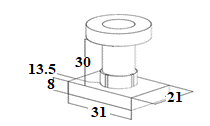
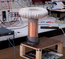
The AutoCAD is used to draw the mechanical parts based on the outcomes of (1)-(3). Figure 2 illustrates the overall base, tower, and connectors dimensions. The realization of Figure 2 is shown in Figure 3. Figure 3 shows the mechanical designed parameters. Where the primary coil's length is 30 cm, and its diameter is about 12 cm.
Figure 2. AutoCAD mechanical parts of AUM-DRSSTC
Figure 3. The mechanical design implementation
The secondary winding needs a very special attention during building up the prototype. Thus, the designer needs to be careful, because the secondary wire tends to be very thin and weak. Using a fingernail to separate the turns while winding to avoid overlapping and keep the shortest possible distance between each turn. The toroid, usually in a ring shape, which is basically a capacitor that holds the high voltage at the top of the secondary winding, it shields the tesla coil from the corona effect and lowers the resonant frequency of it as well. Usually made of aluminum and used widely in medium sized, an aluminum air duct is a convenient choice as it can be shaped into the desired form easily and due to its properties and its simplicity.
3.2 Electrical design
AUM-DRSSTC comprises an inductor and a capacitor forming a resonant tank. Thus, the oscillation will appear if they are charged, with the proper values of C and L, thus, a high voltage is generated.
The AUM-DRSSTC has two resonant circuits which are the primary coil L1 in series with a capacitor C1 at the base, and the secondary winding L2 coupled with the toroid (top load) at the top of the device which represents the second capacitor C2 with the ground. Thus, the first step towards designing a AUM-DRSSTC is to figure out the proper size of the build, desired output and of course the values of L1, C1 and L2 based on the approximated resonant values. For the inductor and the capacitor to oscillate at the resonant frequency, the following equations are used:
$X_L=X_C$ (3)
$2 \pi f L=\frac{1}{(2 \pi \mathrm{fC})}$ (4)
$f_r=\frac{1}{(2 \pi \sqrt{L C})}$ (5)
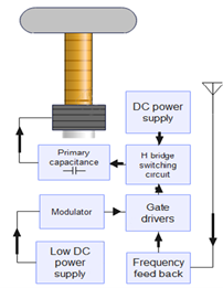
The block diagram of Figure 4 shows the main components of the AUM-DRSSTC design. ADC power source supplies the tesla resonator with the desired input voltage, the switching circuit is responsible of allowing the flow of current from the DC power to the primary coil at an initial frequency f1, which is created by an external modulator.
This signal controls the gate drive circuit. Therefore, the gate drive circuit will control the switching time of H-bridge switches. As for the feedback system it may be chosen between a current transformer or a wire antenna in order to receive the resonant frequency f2 from the tesla coil and into the self-resonant driver, which will replace the external modulator signal by using jumpers.
Figure 4. AM-AUM-DRSSTC block diagram
Based on aforementioned discussion, the selected components are: four high power IGBTs which should be rated at 600V. Two 555 timers have two duties. First, supply the initial PWM signal. Second, it is responsible for the received feedback signal. Schmitt trigger or two NOT gates are used to invert the signal and supply the complementary gate driver so that they turn on and off at separate periods.
Two IGBT drivers (IR2184) responsible for switching the IGBT’s. They offer a fast-switching time to prevent any expected cross-through between IGBTs on the primary during the switching.
Voltage regulators are used to supply the low voltage and control components, an interrupter (ARDUINO) which will be connected to the interrupt pin in the gate drivers and will turn them off completely when a short circuit occurs (as a protection device). Moreover, it plays back music at a certain given frequency.
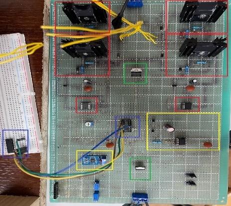
Figure 5. The designed PCB of AUM-DRSSTC
As shown in Figure 5, the components in red are the four IGBTs used to form an H-inverter and one driver per leg. The green rectangles represent the power supply, 12V and 5V voltage regulators to supply both the gate drivers.
Finally, the yellows are the 555 timers one of them is used with variable frequency and duty cycle generation and the other one is connected to the feedback antenna. The operation of the AUM-DRSSTC can be briefly described based on both Faraday’s law and Lenz’s law, in which, the circuit will be implied to the simpler slayer exciter circuit, see Figure 6.
According to Faraday’s second law of electromagnetic induction, it is understood that an induced emf in a coil is equal to the rate of change of flux linkage. Where E is the electromotive force, Φ is the magnetic flux, and N is the number of turns.
Figure 6. Slayer exciter circuit
$E=-N \frac{d \emptyset}{d t}$ (7)
The coil L1 is a wire that is wound a long solenoid around the coil L2, both coils are insulated from each other. Once L1passes current through it, it creates a magnetic field that passes through L2, as the current through L1 is changing magnetic flux, and from Faraday’s and len’z laws, an induced emf can be appeared at L2. The emf through L1 is given by:
$E_{L 1}=M \frac{d I_{L 2}}{d t}$ (8)
where, EL1 is the emf induced in L1, I2 is the current through L2 and M is the mutual inductance which is given by:
$\mathrm{M}=\frac{\mu_o \mu_r N_1 N_2 \mathrm{~A}}{\ell}$ (9)
where, µo is the permeability of free space (4π*10-7), µr is the relative permeability of the soft iron core, N is in the number of coils turns, A is in the cross-sectional area in m2, ℓ is the coils length in meters. The slayer exciter circuit works by supplying current to the base of the IGBT which makes the collector-emitter path of the transistor conductive. Thus, this allows current to flow through the primary coil, the increase in current in the primary coil creates an increasing magnetic flux density. This leads to increase magnetic flux, that induces a voltage into the secondary coil, due to the significant number of turns on the secondary, this voltage is much higher than the primary one and can be calculated using the following:
$V_s=\frac{V_p N_s}{N_p}$ (10)
where, Vs is the secondary voltage, Vp is the primary voltage and Np, and Ns are the number of turns of the primary and secondary windings, respectively.
Figure 7. Half wave (Top) and full wave configurations (Bottom)
With the proper selection of toroid attached to the secondary wire, a resonance tank circuit is formed to naturally oscillates at its resonance frequency. When the system oscillates, the induced voltage creates a positive potential at the top of the coil, and a negative one at the bottom, once the negative voltage exceeds the reverse voltage of the LED the base of the transistor is pulled to low and the IGBT stops allowing current to pass through the primary causing it to turn off. This process keeps repeating powering the system on and off, and due to the resonance of the secondary side a sinusoidal voltage/current are created with a very high frequency. This process keeps going from the primary to secondary side of the coil which is considered as a load to H-bridge inverter (full bridge), see Figure 7 (bottom).
The reason for a full bridge with four transistors instead of a half bridge (top of Figure 7), is that when applying for instance 30V DC the half bridge clips out part of the voltage and can only create positive 15V across the primary coil. On the other hand, a full bridge can utilize the complete supply voltage, positive and negative, and thus can obviously generate bigger arcs. As for the IGBTs, they are chosen IRGP50B60PD1. They have some features such as they offer fast switching time, have a high rated current, and high rated voltage.
The toroid basically acts as a capacitor. It will charge and discharge the arcs of the mechanical parameters that are mentioned in the mechanical design. An input voltage of 15V which will then be bucked to supply the voltage regulators by 5V and 12V to supply the control circuit. Then, 7805-voltage regulator supplies the Schmitt trigger, Arduino NANO and the 555 timers. The other one is 7812 voltage-regulator that supplies the IGBT drivers. The 555 timer acts as an oscillator and creates a PWM signal with a duty cycle of 50% and a variable frequency from 40khz up to 600khz. This signal at pin 3 is connected to the HIGH input of the left driver. Also, the same pin is connected to the other LOW input of the right IGBT driver. Therefore, the driving signals are generated for all IGBTs.
Finally the interrupter is one of the most common issues in any AUM-DRSSTC circuit is the rather high current consumption of the system caused by the IGBTs which leads to a rising temperature in the IGBTs themselves, the solution to this problem is to utilize an interrupter (ARDUINO NANO) in this case Input connected the D5 pin of the Arduino to the shutdown pin of the IGBT drivers, you can also attach two potentiometers or trimmers to the A 5 and A 0 pins of the Arduino you can output a PWM signal that has a controllable frequency and duty cycle. All used components are listed in Table 1.
Due to the safety regulation in the university labs, and the existence of the DC power supply, it is not allowed to exceed the voltage above certain limits. Thus, to conduct and test the PCB board, a 15 V DC is connected to the PCB and check the effectiveness of the design. Figure 8 shows the functionality of the designed electrical board. This figure shows the output of the full wave inverter or H-Bridge inverter. As seen from this figure, there are two level of the output voltage with voltage peak about 15 V.
This voltage is applied to the primary of the AUM-DRSSTC. Then, the resonance will occur and, thus, the resonance that leads to spark treeing will appear.
It should be noted that, at this low DC input voltage, the spark across the tower of AUM-DRSSTC will not appear unless the secondary side is re-considered and designed according to the 15 V DC input voltage. But still, it is dangerous to deal with this AUM-DRSSTC in the university lab.
Figure 8. The output of full wave configuration
Table 1. List of the used components
|
Component |
Number/rated |
|
Power Supply |
325 V |
|
IRGP50B60PDI |
600 V-IGBT |
|
IGBT driver |
IR2184 |
|
Voltage Regulator |
7812 |
|
Timer |
555-timer |
|
Duty Cycle |
50% |
|
Switching frequency |
200 kHz |
|
Arduino chip |
NANO-chip |
|
Schmitt trigger |
Two |
|
Antenna |
One |
This paper explores a comprehensive design of Audio-Modulated Dual Resonant Solid State Tesla Coil (AUM-DRSSTC) is discussed. The mechanical parts and electrical parameters of AUM-DRSSTC are investigated in detail. The mathematical model is used to simplify the design and parameters’ selection. The results of the introduced design are practically tested in the lab. A 15 kV, 200 kHz prototype is built to prove the design aspects. Challenges of this design is the high voltage value, so the design is tested for low DC voltage to keep safe in the lab.
[1] Akiyama, H., Sakai, S., Sakugawa, T., Namihira, T. (2007). Environmental applications of repetitive pulsed power. IEEE Transactions on Dielectrics and Electrical Insulation, 14(4):825-833. https://doi.org/10.1109/TDEI.2007.4286513
[2] Sakamoto, T., Nami, A., Akiyama, M., Akiyama, H. (2012). A repetitive solid state Marx-type pulsed power generator using multistage switch-capacitor cells. IEEE Transactions on Plasma Science, 40(10): 2316-2321. https://doi.org/10.1109/TPS.2012.2184776
[3] Li, H.T., Ryoo, H.J., Kim, J.S., Rim, G.H., Kim, Y.B., Deng, J. (2008). Development of rectangle-pulse Marx generator based on PFN. IEEE Transactions on Plasma Science, 37(1): 190-194. https://doi.org/10.1109/TPS.2008.2007730
[4] Wu, Y.F., Liu, K.F., Qiu, J., Liu, X.X., Xiao, H.X. (2007). Repetitive and high voltage Marx generator using solid-state devices. IEEE Transactions on Dielectrics and Electrical Insulation, 14(4): 937-940. https://doi.org/10.1109/TDEI.2007.4286529
[5] Furfari, F.A. (2005). A history of the Van de Graaff generator. IEEE Industry Applications Magazine, 11(1): 10-14.
[6] Martins, A.J., Pinto, H.M. (2009). van de Graaff generator. https://studylib.net/doc/18449277/van-de-graaff-generator, accessed on Sep. 22, 2022.
[7] Zhao, L., Su, J.C., Li, R., Xu, X.D., Yu, B.X., Zeng, B. (2019). A novel screw-based probe to measure pulse forming line voltage in tesla-type generators. IEEE Transactions on Plasma Science, 48(10): 3305-3311. https://doi.org/10.1109/TPS.2019.2957978
[8] Su, J.C., Zhang, X.B., Liu, G.Z., Song, X.X., Pan, Y.F., Wang, L.L., Peng, J.C., Ding, Z.J. (2009). A long-pulse generator based on tesla transformer and pulse-forming network. IEEE Transactions on Plasma Science, 37(10): 1954-1958. https://doi.org/10.1109/TPS.2009.2025278
[9] Matsuzawa, H., Suganomata, S. (1982). Design charts for Tesla‐transformer‐type relativistic electron beam generators. Review of Scientific Instruments, 53(5): 694-696. https://doi.org/10.1063/1.1137044
[10] Marincic, S. (1982). Nikola Tesla and the Wireless Transmission of Energy. IEEE Transactions on Power Apparatus and Systems, PAS-101(10): 4064-4068. https://doi.org/10.1109/TPAS.1982.317084
[11] Attaran, M.M.D., Aghdam, E.K., Toroghi, S. (2008). New utilization of compact Tesla transformer for multi-channel triggering of Field distortion spark gap switch. 2008 IEEE 35th International Conference on Plasma Science, Karlsruhe, Germany, pp. 1-1, https://doi.org/10.1109/PLASMA.2008.4591192
[12] Pongsathit, W., Yutthagowith, P., Limcharoen, W. (2017). Solid state tesla transformer for flashover test on suspension insulators. 2017 International Symposium on Electrical Insulating Materials (ISEIM), Toyohashi, Japan, pp. 239-242. https://doi.org/10.23919/ISEIM.2017.8088731
[13] Brussaard, S., Vyuga, D. (2004). A 2.5-MV subnanosecond pulser with laser-triggered spark gap for the generation of high-brightness electron bunches. IEEE Transactions on Plasma Science, 32(5): 1993-1997. https://doi.org/10.1109/TPS.2004.835479
[14] Smith, Ø. (2017). Analysis of design parameters in a musical dual resonant solid state Tesla coil. Norwegian University of Science and Technology, Norway.
[15] Ghilinţă, C.D., Stegaru, S.C., Popeea T., Ţăpuş, N. (2015). Portable audio-modulated Tesla coil for demonstrative actions. 2015 14th RoEduNet International Conference - Networking in Education and Research (RoEduNet NER), Craiova, Romania, pp. 238-241. https://doi.org/10.1109/RoEduNet.2015.7312002
[16] McHutchon, A. (2013). RLC Resonant Circuits. Cambridge Machine Learning Group, 1-7.
[17] Principles of Audio-Rate Frequency Modulation. http://www.moz.ac.at/sem/lehre/lib/ks/lib/fm/fm.htm.html, accessed on Jan. 17, 2023.