Anumut Siricharoenpanitch | Jarinee Jongpleampiti | Nittaya Naphon | Smith Eiamsa-ard | Paisarn Naphon*
© 2022 IIETA. This article is published by IIETA and is licensed under the CC BY 4.0 license (http://creativecommons.org/licenses/by/4.0/).
OPEN ACCESS
The flow and heat transfer characteristics in the corrugated tube mainly depend on flow parameters and geometric configurations of the tube, such as corrugated cross-section, corrugated angle, corrugated arrangement, corrugated pitch and depth, pulsating flow frequency, coolant types, and Reynolds number. This paper presents the pulsating thermal characteristics of ferrofluid flowing in the fluted tube using the de-ionized water and 0.015% by volume as working fluid flowing in the test section. Eulerian two-phase turbulence model validation has been performed in both steady and pulsating flow. The finite volume approach discretizes the Eulerian two-phase model. Numerical results indicate that the longitudinal and transverse secondary flows are induced differently via the pulsating flow. The heat transfer characteristics of pulsating fluid flow are significantly larger than that of continuous fluid flow. A higher pulsating frequency induces a heat transfer enhancement. However, pulsating flow increases pressure due to more flow complexity and rough augmentation. Due to the disturbed fluid flow and higher swirling motion, the heat transfer augmentation increases and corresponds with the published results.
numerical study, pulsating flow, corrugated tube, ferrofluid
Heat exchanger technology has been interested in growing in the various thermal systems and is the major component of household applications, including heating and air conditioning systems. Energy consumption control is required for many systems. As more than 90% of thermal energy in thermal systems transits within heat exchangers, their optimization has become mandatory. The common heat transfer performance improvement is the fluid velocity manipulating inside the system or inserts in the case of turbulent generators. Passive techniques focus on the flow characteristics inside tubes and the modified tube surface with different configurations and sometimes combined roughness and surface extension. In contrast, the active methods concentrate on the modified mixing level. The tube’s surface vibration significantly affects the heat transfer enhancement. Fluid vibration can be extensively investigated in both air and liquid as coolant, and most of the previous studies had been performed by Naphon et al. [1-12]. They studied the thermal performance improvement of the relevant devices with different methods: Passive, active, and combined methods. However, the thermal conductivity modification of coolant has significant effects on the thermal performance of the helical tubes [13-15], the helically coiled tuber [16], the corrugated tube [17], and a spirally corrugated tube [18]. Next, Wang et al. [19] considered the grooved pitch on the thermal performance via nanofluid as a coolant. Besides, magnetic field and nanofluid on the thermal cooling efficiency [20] and xanthan gum [21] as coolants have been investigated. Next, the thermal distribution and flow behaviors flowing through the corrugated tube have been analyzed via the finite element method [22-23]. Some works focus on the flow and thermal distributions for the thermal system with corrugated channels. The temperature and flow behaviors of working in the channel with different geometrical dimensions have been investigated [24-28]. Besides, different flow configurations have been studied [29-34]. Some papers recently considered the porous fin configuration's effect on the fluted tubes' performance [35-38]. Hojati et al. [39] studied the heat transfer in the inclined groove tube and entropy generation in the spirally corrugated pipes [40] using refrigerant as a working fluid.
Besides, many works considered the pulsating fluid flow behaviors of the various thermal devices. Yang et al. [41] investigated the inlet vapor quality of an evaporator's two-phase flow pattern of R134a. Some works presented the transient fluid flow in the ribbed channels [42], in a manifold microchannel heat sink [43], and a rectangular channel [44]. Next, Bizhaem et al. [45] investigated the pulsating thermal improvement in the coiled tube, pulsating flow FC-72 heat transfer enhancement [46], and the heat transfer behaviors in the engine [47]. Xu et al. [48] considered the pulsating GOPs-water flowing in a microchannel and a ribbed channel [49]. Kurtulmu and Sahin [50] presented the fluid and temperature distributions in the sinusoidal channel. Next, Davletshin et al. [51] studied the heat transfer of steady and pulsating air flowing through a spanwise rib. Recently, Hoang et al. [52] applied the LES method under pulsating inlet conditions to consider flow characteristics in a channel embedded with V-sharp. Next, Mucci et al. [53] numerically investigated pulsating flow behaviors inside the heat pipes. For the experimental study, the most transient nanofluid flowing through in the various flow channel configurations are analyzed [54-60].
As outlined above, many papers have concentrated on the flow and heat transfer characteristics in corrugated tubes with different types of nanofluid. Almost works have been performed based on the experiment with continuous flow, while the pulsating heat transfer and flow behaviors flowing the corrugated tubes are still limited. The experiment cannot be analyzed and/or predict the flow behaviors near the boundary layer zone of the corrugated tube, which results in the heat transfer enhancement, while the computational study can be performed to find better the heat transfer and flow behaviors. The previous works [54-60] experimentally studied the pulsating heat transfer characteristics using nanofluid flowing in the spirally coiled tube [54, 55], in the corrugated tubes [56], in the micro-fin tube [57], and in the fluted tube [58, 59]. While the flow and heat transfer characteristics of nanofluid flowing in the fluted tube for the continuous flow are predicted by Siricharoenpanitch et al. [60] and compared with the measured results [58, 59]. However, they do not consider the flow behavior for the pulsing flow. Therefore, the current work is continuously performed from those studies [54-60] in which the numerical analysis of pulsating ferrofluid flows in the fluted tube. As the results from the previous work [5] show, the Eulerian two-phase turbulent modeling gives the highest accuracy compared to the measured data. Therefore, the two-phase model is used to evaluate the temperature behaviors of ferrofluid with different pulsating flow frequencies flowing through the fluted tube, which the obtained are validated with the experimental results [59, 60].
2.1 Defining the model
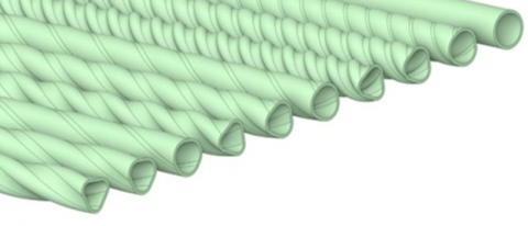
The physical models in this study are shown in Figure 1. The tube's length is 60.00 and 10.70 mm for the tube diameter, and the details of the system are shown in Table 1. The nanofluid is a homogeneous mixture with 0.015% by volume concentration. The constant power input at the outer wall of the corrugated tube is kept constant at 136 W. In order to simplify the numerical model process, some assumptions are listed as follows: (1) The nanofluid is a homogeneous mixture, (2) The steady flow of the incompressible fluid is considered, (3) There are no interaction or phase changes in the nanofluid, (4) The viscous dissipation term is excluded, (5) The thermophysical characteristics are temperature independent, and the pressure at the tube outlet opens to the atmosphere.
2.2 Main governing equations
Mathematical models are performed with ferrofluid as coolant flowing into the fluted tube with different details (Table 1 and Figure 1). The governing equations are presented as a separate phase [61, 62]. Flow and heat transfer behaviors of each phase (Eulerian two-phase flow model) are described using the following equations:
$\nabla\left(\rho_p \phi_p V_p\right)=0$ (1)
$\nabla\left(\rho_l \phi_l V_l\right)=0$ (2)
$\nabla\left(\rho_p \phi_p V_p V_p\right)=\phi_p \nabla P$$+\nabla\left(\phi_p \mu_p\left(\nabla V_p+\nabla V_p T\right)\right)-F_d+F_{V m}+F_{c d}$ (3)
$\nabla\left(\rho_l \phi_l V_l V_l\right)=\phi_l \nabla P$$+\nabla\left(\phi_l \mu_l\left(\nabla V_l+\nabla V_l T\right)\right)+F_d+F_{V m}$ (4)
$\phi_l+\phi_p=1$ (5)
Figure 1. Test section configuration in the present analysis
Table 1. Details of the test sections
|
Tubes |
Coolants |
Helical depth (mm) |
Helical pitch (mm) |
Symbols |
|
Smooth |
Water |
0 |
0 |
#1 |
|
Smooth |
Ferrofluid |
0 |
0 |
#2 |
|
Fluted tube |
Ferrofluid |
0.5 |
10 |
#3 |
|
Fluted tube |
Ferrofluid |
1.0 |
10 |
#4 |
|
Fluted tube |
Ferrofluid |
1.5 |
10 |
#5 |
|
Fluted tube |
Ferrofluid |
0.5 |
20 |
#6 |
|
Fluted tube |
Ferrofluid |
1.0 |
20 |
#7 |
|
Fluted tube |
Ferrofluid |
1.5 |
20 |
#8 |
|
Fluted tube |
Ferrofluid |
0.5 |
30 |
#9 |
|
Fluted tube |
Ferrofluid |
1.0 |
30 |
#10 |
|
Fluted tube |
Ferrofluid |
1.5 |
30 |
#11 |
Due to the small size of the nanoparticles and the very lean nanofluid concentration for this study, the lift force is excluded. The importance of the different terms (drag, virtual mass, and particle-particle interaction force) in the momentum equation is discussed and considered in the work [63]. Drag force interaction of nanofluid (the base fluid and the nanoparticles) is only considered and can be determined from the following equations:
$F_d=-\beta\left(V_l-V_p\right)$ (6)
$\beta=\frac{3}{4} C_d \phi_l\left(1-\phi_l\right) \frac{\rho_l}{d_p}\left(V_l-V_p\right) \phi_l^{-265}$ (7)
$C_d= \begin{cases}\frac{24}{\operatorname{Re}_p}\left(1+0.15 \operatorname{Re}_p^{0.687}\right) & \operatorname{Re}_p<1000 \\ 0.44 & \operatorname{Re}_p>1000\end{cases}$ (8)
$\operatorname{Re}_p=\frac{\phi_l \rho_l\left|V_l-V_p\right| d_p}{\mu_l}$ (9)
The Eulerian model used in this study with the mentioned above assumption is presented as follows;
$\nabla\left(\rho_l \phi_l C_{p, l} T_l V_l\right)=\nabla\left(\phi_l k_l \nabla T_l\right)-h_v\left(T_l-T_p\right)$ (10)
$\nabla\left(\rho_p \phi_p C_{p, p} T_p V_p\right)$$=\nabla\left(\phi_p k_p \nabla T_p\right)-h_v\left(T_l-T_p\right)$ (11)
$\frac{h_p d_p}{k_l}=\left(2+1.1 \operatorname{Re}_p^{0.6} \operatorname{Pr}^{1 / 3}\right)$ (12)
$h_v=\frac{6\left(1-\phi_l\right)}{d_p} h_p$ (13)
$k_l=\frac{k_{b l}}{\phi_l}, k_p=\frac{k_{b p}}{\phi_p}$ (14)
$k_{b l}=\left(1-\sqrt{\left(1-\phi_l\right)}\right) k_l$ (15)
$k_{b p}=k_l(\omega A+[1-\omega] \Gamma)\left(\sqrt{\left(1-\phi_l\right)}\right)$ (16)
$\Gamma=\frac{2}{\left(1-\frac{B}{A}\right)}\left\{\frac{B}{A} \frac{(A-1)}{\left(\frac{A-B}{A}\right)^2}\right\} \ln \left(\frac{A}{B}\right)$$-\frac{A(B-1)}{(A-B)}-\frac{B+1}{2}$ (17)
$A=\frac{{ }^{k_p}}{k_l}$ and $\omega=7.26 \times 10^{-3}$, $B=1.25\left(\frac{1-\phi_l}{\phi_l}\right)^{10 / 9}$ (18)
Table 2 shows the properties of the Fe3O4 nanoparticles. The published correlations [64-67] are used in the calculated ferrofluid (Fe3O4/water nanofluid) properties as follows;
$\mu_{n f}=(1+2.5 \phi) \mu_w$ (19)
$k_{n f}=\left[\frac{k_p+2 k_w-2 \phi\left(k_w-k_p\right)}{k_p+2 k_w+\phi\left(k_w-k_p\right)}\right] k_w$ (20)
$\rho_{n f}=\phi \rho_p+(1-\phi) \rho_w$ (21)
$\left(\rho C_p\right)_{n f}=\phi\left(\rho C_p\right)_p+(1-\phi)\left(\rho C_p\right)_w$ (22)
Figure 2. (a) Grid configuration for the numerical analysis and (b) selected reference positions to illustrate the results
Table 2. Thermophysical properties of water, Fe3O4 (25℃)
|
Properties |
Fe3O4 |
|
Density, $\rho$ (kg/m3) |
5180 |
|
Thermal conductivity, $k$ (W/moC) |
80.4 |
|
Viscosity, $\mu$ (mPa S) |
- |
|
Specific heat, $C_p$ (J/kg.K) |
670 |
|
Purity, (%) |
>99.9 |
|
Average diameter, (nm) |
23 |
2.3 Boundary conditions
The boundary condition values of the system for the calculation processes are listed as follows:
Inlet: The sinusoidal function sets the inlet velocity magnitude under pulsating flow conditions.
$V_{\text {in }}=V_O+A_O \sin \left(2 \pi f_r \cdot t\right)$ (23)
where, Ao is the non-dimensional pulsating amplitude. Three different values are used for the Ao variable in the velocity equation the inlet of the channel (Ao= 0.2-1.0) and fr the pulsating frequency (10, 20, 30 Hz).
- Outlet: $P_{o u t}=P_{a m b i}$
- Outer wall: $q=q_{i n}$
- Inner wall: no-slip condition
- Outer wall: the constant power input = 136W.
Ansys Fluent commercial software is applied to solve all pulsating flow conditions in the simulation process. The high-order discretization accuracy has been used to solve the pressure-velocity coupling problem. It is essential in the numerical procedure for the boundary layer zone. Therefore, a non-uniform mesh generates finer mesh for this zone, as shown in Figure 2 (a). The numerical method is calculated under uniform heat input (136W) and 10, 20, and 30 Hz pulsating flow frequencies. The root means square of the residual parameter is below 10-6.
2.4 Grid independent test
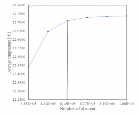
The grid independence check in the numerical procedure is performed on the different grid sizes. This method can be done by changing the number of nodes of the model and simulating while the other relevant parameters are kept constant. The number of nodes is changed from coarse mesh to fine mesh (481,000, 615,000, 670,000), as shown in Figure 3. The changing of outlet coolant temperature depends on the number of nodes, and the different outlet temperature obtained from the grid numbers = 615,000 and 670,000 is less than 1%. This means that the predicted results are independent regarding the grid number value higher than 615,000. Therefore, the results obtained from the grid number = 615,000 is sufficient in the numerical process. Meanwhile, the computer system used in the numerical analysis has processor cores = 18 and RAM = 96 GB of memory for the calculation process.
Figure 3. Grid independent test
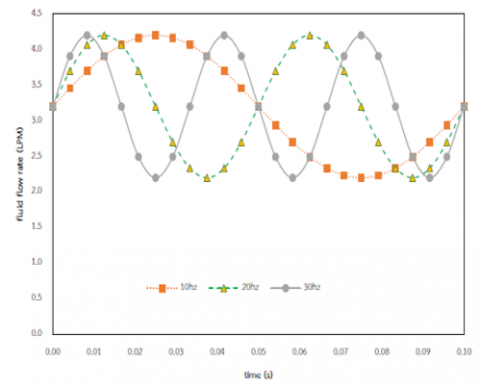
The two-phase turbulent model is applied to solve ferrofluid flow in the fluted tubes, as shown in Figure 1. Sinusoidal time-dependent velocity $V_{i n}=V_o+A \sin \left(2 \pi f_r \cdot t\right)$ and the inlet uniform temperature are set for the inlet condition, in which the tube's length and diameter are 60.00 and 10.70 mm, respectively. The sinusoidal time-dependent flow characteristics used in the numerical study for pulsating flow conditions for different pulsating frequencies are shown in Figure 4.
Figure 4. Variation of coolant flow rate for different pulsating fluency
The results (pulsating flow conditions) are validated by simulating them under the same conditions as the measured data from Siricharoenpanitch et al. [59, 60]. The same test section, coolant flow rate condition, and power input are selected with the same solver setting. The predicted results are compared at three different test sections and two different coolant types, as shown in Table 3. The comparisons are well-matched with the measured data [59, 60] and give a maximum error of 6.80% (Table 3). In addition, the measured data [59, 60] have been verified with those from the correlations. Moreover, they confirm the predicted results [59] for the continuous flow conditions.
As shown in Table 1, the computational domain is the fluted tube with a length of 60 mm and 10.70 mm in diameter and with two coolant types (water and ferrofluid) under constant power input (136 W). The different positions along the fluted tubes used in the presented results are shown in Figure 2 (b).
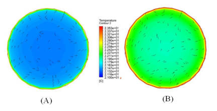
Figure 5 shows the temperature distributions in the plain tube for water and ferrofluid continuous flow. The temperature distributions from those are similar. However, the temperature gradient (the central zone and near the tube wall zone) for ferrofluid as coolant is less than for water. The thermal properties of ferrofluid are more significant than that of water. This results in a higher heat transfer capability. This means that the temperature gradient for ferrofluid is lower than for water, as shown in Figure 5. The result trends also correspond with the measured data from [59, 60].
Table 3. Comparison between the predicted results for pulsating flow with the measured data [60]
|
Fluted tube |
Coolants |
Coolant temperature (℃) at x=150 mm |
% Errors |
|
|
Measured data |
Predicted results |
|||
|
Helical depth=0.5 mm, helical pitch=10 mm |
Water |
21.23 |
21.55 |
1.54 |
|
Helical depth=1.0 mm, helical pitch=10 mm |
Water |
21.56 |
21.78 |
1.02 |
|
Helical depth=1.5 mm, helical pitch=10 mm |
Water |
21.87 |
22.43 |
2.53 |
|
Helical depth=0.5 mm, helical pitch=10 mm |
Ferrofluid |
23.03 |
24.65 |
6.80 |
|
Helical depth=0.5 mm, helical pitch=20 mm |
Ferrofluid |
22.45 |
23.87 |
6.13 |
|
Helical depth=0.5 mm, helical pitch=30 mm |
Ferrofluid |
21.89 |
22.13 |
1.09 |
Figure 5. Temperature distribution in the smooth tube for (A) water, and (B) ferrofluid
Figure 6. Temperature distribution of ferrofluid in the smooth tube and fluted tube with helical pitch=30 mm for (A) smooth tube, (B) helical depth=0.5 mm, (C) helical depth=1.0 mm, and (D) helical depth=1.5 mm
Figure 6 shows the temperature distribution of ferrofluid for continuous flowing inside the tube with different configurations. A higher tube wall temperature for the plain tube is obtained compared with the fluted tube. Therefore, the heat transfer capability is larger than the plain tube. Due to the swirling flows by the corrugated surface, the mixing level for the fluted tube is higher than that for the plain tube, which a higher for increasing helical depth. Therefore, the temperature difference between the main flow at the central zone and fluid near the tube wall zone for a fluted tube is less than for a plain tube, as shown in Figure 6. In addition, decreasing helical pitch increases the mixing level, resulting in lower temperature gradients, as shown in Figure 7. Besides, the predicted results correspond to the measured data [59, 60].
Figure 7. Temperature distribution of ferrofluid in the smooth tube and fluted tube with helical pitch=10 mm for (A) smooth tube, (B) helical depth=0.5 mm, (C) helical depth=1.0 mm, and (D) helical depth=1.5 mm
Figure 8 shows the coolant temperature variation along the tube length at R=4.5 mm. The larger coolant temperatures are obtained at a higher distance from the entrance for all cases. It is seen that the oscillations of the temperature are not found for the continuous flow condition in the plain tube. However, the temperature of ferrofluid is more prominent than those of water. This is caused by higher thermal conductivity values on the heat transfer enhancement. However, the oscillation temperature level in the fluted tube is more than in the plain tube. This may be due to the corrugated ribs significantly impacting the turbulent mixing level. Moreover, the streamlines for ferrofluid flowing in the fluted tube with pulsating flow conditions are more prominent peak oscillation due to the fluted ribs and pulsating flow and have an effect on the temperature oscillation peak (Figure 8).
Figure 8. Variation of coolant temperature for pulsating flow frequency=10Hz at R=4.5 mm
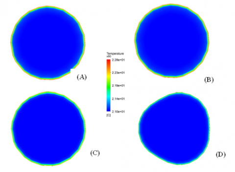
Figure 9. Variation of temperature at x=60 mm, for (A) water continuous flow in smooth tube, (B) water flow in smooth tube with pulsating frequency=10 Hz mm, t=0.025s, (C) ferrofluid flow in smooth tube with pulsating frequency=10 Hz mm, t=0.025s, and (D) ferrofluid flow in fluted tube with helical depth=0.5 mm, helical pitch=30 mm with pulsating frequency=10 Hz, t=0.025s
The swirling flow direction and turbulent intensity of coolant are induced as in the fluted tube, which significantly affects the fluctuation and mixing levels of two zones (core and near-wall zones). The fluid oscillation level tends to increase at a higher distance. This results in a reduced temperature difference between the main fluid flow and the fluid near the fluted wall, as shown in Figures 9-10.
Figure 10. Variation of temperature at x=60 mm, for (A) water continuous flow in smooth tube, (B) water flow in smooth tube with pulsating frequency=10 Hz mm, t=0.10s, (C) ferrofluid flow in smooth tube with pulsating frequency=10 Hz mm, t=0.10s, and (D) ferrofluid flow in fluted tube with helical depth=0.5 mm, helical pitch=30 mm with pulsating frequency=10 Hz, t=0.10s
Figure 11. Temperature distribution along the corrugated tube for pulsating flow frequency = 30Hz at 1.0s
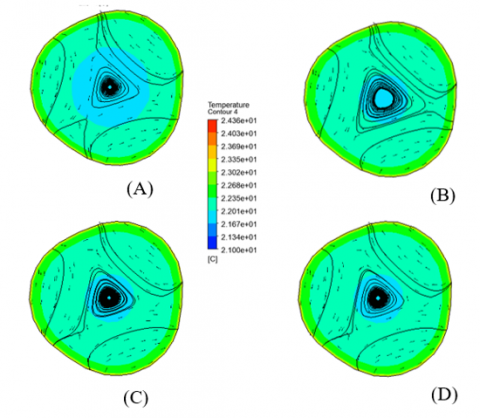
Figure 12. Temperature distribution, velocity vector and path line at x=600 mm and t= 1.0s for pulsating frequency (A) 0Hz, (B) 10Hz, (C) 20Hz, and (D) 30Hz
Figure 13. Average temperature at x=600 mm and t= 1.0s for different flow frequency
The parameter distributions flowing in the corrugated tubes at various positions for pulsating flow frequency=30Hz at 1.0s are shown in Figure 11. At the inlet port, the velocity profile looks similar to the velocity peak in the straight tube, in which the maximum velocity occurs at the central zone of the tube. Figure 11 also shows the temperature profile variation flowing through the corrugated tube at different positions. It is found that the temperature of coolant increases with increasing distance from the inlet port.
Figure 12 shows the temperature distribution, velocity vector, and path line at x=600 mm and t= 1.0s for pulsating frequency (A) 0Hz, (B) 10Hz, (C) 20Hz, and (D) 30Hz. As expected, the cooling capacity of the coolant depends on its flow rate and frequency. In corrugated tubes, the corrugation acts like artificial roughness. The helical corrugation and pulsating flow cause an extra decrease in the boundary layer zone by creating chaotic mixing and secondary flow. Therefore, flowing in the corrugated tube with pulsating flow conditions yields an increase in the heat transfer rate. In addition, due to the higher turbulent intensity and higher nanoparticle mixing, the heat transfer rate is significantly greater than it is for continuous flow conditions. Higher pulsating flow frequency gives higher turbulent intensity and higher nanoparticle mixing. Therefore, an average coolant temperature increases with increasing flow frequency, as shown in Figure 13, and corresponds with the experimental results [59, 60].
Pulsating forced convection of ferrofluids flowing through the fluted tube has been investigated. This study is done for different tube configurations and three pulsating frequencies (10, 20, 30Hz) under constant heat flux. When changes in different tube configurations (helical depth and helical pitch) are examined, it is found that the turbulent intensity of the central core flow and the fluid near the fluted surface is increased, which significantly affects the mixing level and more heat transfer. Within a period of pulsating, the change of flow behavior is intimately associated with the acceleration or deceleration of each phase. Everything occurs as if the pulsating is a turbulent generator modulating in time and favoring heat transfer and pressure loss. The increase in pulsating flow frequency increases the streamline oscillation, especially in the fluid near the fluted surface, which results in a more significant mixing level and heat transfer enhancement. In addition, the modification of the working fluid properties and flow behaviors are achieved, and the heat transfer capabilities of the ferrofluids are better than water. The results from this study are used to develop a knowledge base that can be used to a design and to develope the heat transfer devices for higher thermal performance and and consequence decrease energy consumption of the system.
The Faculty of Engineering has supported this work. The authors would like to thank the Faculty of Engineering, Srinakharinwirot University (SWU).
|
Cp |
specific heat, [kJ kg-1oC-1] |
|
d |
diameter, [m] |
|
F |
force, [N] |
|
Ferrofluid |
Fe3O4/water nanofluid |
|
k |
thermal conductivity, [kW m-1 ℃-1] |
|
P |
pressure, [kPa] |
|
q |
heat flux, [kW m-2] |
|
R |
radius, [mm] |
|
T |
temperature, [℃] |
|
V |
velocity, [m s-1] |
|
Greek symbols |
|
|
$\phi$ |
nanofluids concentration, [%] |
|
$\rho$ |
density, [kg m-3] |
|
$\mu$ |
viscosity, [kg m-1s-1] |
|
Subscripts |
|
|
d |
drag force |
|
cd |
drag coefficient |
|
l |
liquid |
|
nf |
nanofluids |
|
p |
particles |
|
Vm |
virtual mass |
|
w |
water |
[1] Naphon, P., Sriromruln, P. (2006). Single-phase heat transfer and pressure drop in the micro-fin tubes with coiled wire insert. International Communications in Heat and Mass Transfer, 33(2): 176-183. https://doi.org/10.1016/j.icheatmasstransfer.2005.08.012
[2] Naphon, P., Sookkasem, A. (2007). Investigation on heat transfer characteristics of tapered cylinder pin fin heat sinks. Energy Conversion and Management, 48: 2671-2679. https://doi.org/10.1016/j.enconman.2007.04.020
[3] Naphon, P., Kornkumjayrit, L. (2008). Numerical analysis on the fluid flow and heat transfer in the channel with V-shaped wavy lower plate. International Communications in Heat and Mass Transfer, 35: 839-843. https://doi.org/10.1016/j.icheatmasstransfer.2008.03.010
[4] Naphon, P., Wongwises, S., Wiriyasart, S. (2013). Application of two-phase vapor chamber technique for hard disk drive cooling of PCs. Int. Comm. International Communications in Heat and Mass Transfer, 40: 32-35. https://doi.org/10.1016/j.icheatmasstransfer.2012.10.014
[5] Naphon, P., Nakharintr, L. (2015). Turbulent two-phase approach model for the nanofluids heat transfer analysis flowing through the minichannel heat sinks. International Journal of Heat and Mass Transfer, 82: 388-395. https://doi.org/10.1016/j.ijheatmasstransfer.2014.11.024
[6] Naphon, P. (2016). Experimental investigation the nanofluids heat transfer characteristics in horizontal spirally coiled tubes. International Journal of Heat and Mass Transfer, 93: 293-300. https://doi.org/10.1016/j.ijheatmasstransfer.2015.09.089
[7] Naphon, P. (2016). Experimental investigation the nanofluids heat transfer characteristics in horizontal spirally coiled tubes. International Journal of Heat and Mass Transfer, 93: 293-300. https://doi.org/10.1016/j.ijheatmasstransfer.2015.09.089
[8] Naphon, P., Wiriyasart, S., Arisariyawong, T., Nualboonrueng, T. (2017). Magnetic field effect on the nanofluids convective heat transfer and pressure drop in the spirally coiled tubes. International Journal of Heat and Mass Transfer, 110: 739-745. https://doi.org/10.1016/j.ijheatmasstransfer.2017.03.077
[9] Nakharintr, L., Naphon, P., Wiriyasart, S. (2018). Effect of jet-plate spacing to jet diameter ratios on nanofluids heat transfer in a mini-channel heat sink. International Journal of Heat and Mass Transfer, 116: 352-361. https://doi.org/10.1016/j.ijheatmasstransfer.2017.09.037
[10] Naphon, P., Nakharintr, L., Wiriyasart, S. (2018). Continuous nanofluids jet impingement heat transfer and flow in a micro-channel heat sink. International Journal of Heat and Mass Transfer, 126: 924-932. https://doi.org/10.1016/j.ijheatmasstransfer.2018.05.101
[11] Naphon, P., Wiriyasart, S. (2018). Experimental study on laminar pulsating flow and heat transfer of nanofluids in micro-fins tube with magnetic fields. International Journal of Heat and Mass Transfer, 118: 297-303. https://doi.org/10.1016/j.ijheatmasstransfer.2017.10.131
[12] Naphon, P., Wiriyasart, S., Arisariyawong, T., Nakharintr, L. (2019). ANN, numerical and experimental analysis on the jet impingement nanofluids flow and heat transfer characteristics in the micro-channel heat sink. International Journal of Heat and Mass Transfer, 131: 329-340. http://doi.org/10.1016/j.ijheatmasstransfer.2018.11.073
[13] Darzi, A.A.R., Farhadi, M., Sedighi, K., Shafaghat, R., Zabihi, K. (2012). Experimental investigation of turbulent heat transfer and flow characteristics of SiO2/water nanofluid within helically corrugated tubes. International Communications in Heat and Mass Transfer, 39: 1425-1434. https://doi.org/10.1016/j.icheatmasstransfer.2012.07.027
[14] Darzi, A.A.R., Farhadi, M., Sedighi, K., Aallahyari, S., Delavar, M.A. (2013). Turbulent heat transfer of Al2O3-water nanofluid inside helically corrugated tubes: Numerical study. International Communications in Heat and Mass Transfer, 41: 68-75. https://doi.org/10.1016/j.icheatmasstransfer.2012.11.006
[15] Darzi, A.A.R., Farhadi, M., Sedighi, K. (2014). Experimental investigation of convective heat transfer and friction factor of Al2O3/water nanofluid in helically corrugated tube. Experimental Thermal and Fluid Science, 57: 188-199. https://doi.org/10.1016/j.expthermflusci.2014.04.024
[16] Khairul, M.A., Hossain, A., Saidur, R., Alim, M.A. (2014). Prediction of heat transfer performance of CuO/water nanofluids flow in spirally corrugated helically coiled heat exchanger using fuzzy logic technique. Computers & Fluids, 100: 123-129. https://doi.org/10.1016/j.compfluid.2014.05.007
[17] Qi, C., Wan, Y.L., Li, C.Y. Han, D.T., Rao, Z.H. (2017). Experimental and numerical research on the flow and heat transfer characteristics of TiO2-water nanofluids in a corrugated tube. International Journal of Heat and Mass Transfer, 115: 1072-1084. https://doi.org/10.1016/j.ijheatmasstransfer.2017.08.098
[18] Xin, F., Liu, Z., Zheng, N., Liu, P., Liu, W. (2018). Numerical study on flow characteristics and heat transfer enhancement of oscillatory flow in a spirally corrugated tube. International Journal of Heat and Mass Transfer, 127: 402-413. https://doi.org/10.1016/j.ijheatmasstransfer.2018.06.139
[19] Wang, G., Qi, C., Liu, M., Li, C., Yan, Y., Liang, L. (2019). Effect of corrugation pitch on thermo-hydraulic performance of nanofluids in corrugated tubes of heat exchanger system based on exergy efficiency. Energy Conversion and Management, 186: 51-65. https://doi.org/10.1016/j.enconman.2019.02.046
[20] Mei, S., Qi, C., Luo, T., Zhai, X., Yan, Y. (2019). Effects of magnetic field on thermo-hydraulic performance of Fe3O4-water nanofluids in a corrugated tube. International Journal of Heat and Mass Transfer, 128: 24-45. https://doi.org/10.1016/j.ijheatmasstransfer.2018.08.071
[21] Zhang, Y., Zhou, F., Kang, J. (2020). Flow and heat transfer in drag-reducing polymer solution flow through the corrugated tube and circular tube. Applied Thermal Engineering, 174: 115185. https://doi.org/10.1016/j.applthermaleng.2020.115185
[22] Yang, C., Liu, G., Zhang, J., Qian, J.Y. (2020). Thermohydraulic analysis of hybrid smooth and spirally corrugated tubes. International Journal of Thermal Sciences, 158: 106520. https://doi.org/10.1016/j.ijthermalsci.2020.106520
[23] Qian, J.Y., Yang, C., Chen, M.R., Jin, Z.J. (2020). Thermohydraulic performance evaluation of multi-start spirally corrugated tubes. International Journal of Heat and Mass Transfer, 156: 119876. https://doi.org/10.1016/j.ijheatmasstransfer.2020.119876
[24] Ahmed, M.A., Yusoff, M.Z., Shuaib, N.H. (2013). Effects of geometrical parameters on the flow and heat transfer characteristics in trapezoidal-corrugated channel using nanofluid. International Communications in Heat and Mass Transfer, 42: 69-74. https://doi.org/10.1016/j.icheatmasstransfer.2012.12.012
[25] Ahmed, M.A., Yusoff, M.Z., Ng, K.C., Shuai, N.H. (2014). Effect of corrugation profile on the thermal-hydraulic performance of corrugated channels using CuO-water nanofluid. Case Studies in Thermal Engineering, 4: 65-75. https://doi.org/10.1016/j.csite.2014.07.001
[26] Ahmed, M.A., Yusoff, M.Z., Ng, K.C., Shuai, N.H. (2015). Numerical investigations on the turbulent forced convection of nanofluids flow in a triangular-corrugated channel. Case Studies in Thermal Engineering, 6: 212-225. https://doi.org/10.1016/j.csite.2015.10.002
[27] Ahmed, M.A., Yusoff, M.Z., Ng, K.C., Shuai, N.H. (2015). Numerical and experimental investigations on the heat transfer enhancement in corrugated channels using SiO2-water nanofluid. Case Studies in Thermal Engineering, 6: 77-92. https://doi.org/10.1016/j.csite.2015.07.003
[28] Selimefendigil, F., Oztop, H.F. (2017). Forced convection and thermal predictions of pulsating nanofluid flow over a backward facing step with a corrugated bottom wall. International Journal of Heat and Mass Transfer, 110: 231-247. https://doi.org/10.1016/j.ijheatmasstransfer.2017.03.010
[29] Ajeel, R.K., Salim, W.S.I.W., Hasna, K. (2018). Thermal and hydraulic characteristics of turbulent nanofluids flow in trapezoidal-corrugated channel: Symmetry and zigzag shaped. Case Studies in Thermal Engineering, 12: 620-635. http://doi.org/10.1016/j.csite.2018.08.002
[30] Ajeel, R.K., Salim, W.S.I.W., Hasna, K. (2019). Influences of geometrical parameters on the heat transfer characteristics through symmetry trapezoidal-corrugated channel using SiO2-water nanofluid. International Communications in Heat and Mass Transfer, 101: 1-9. https://doi.org/10.1016/J.ICHEATMASSTRANSFER.2018.12.016
[31] Ajeel, R.K., Salim, W.S.I.W., Hasna, K. (2019). Turbulent convective heat transfer of silica oxide nanofluid through corrugated channels: An experimental and numerical study. International Journal of Heat and Mass Transfer, 145: 118806. https://doi.org/10.1016/j.ijheatmasstransfer.2019.118806
[32] Ajeel, R.K., Salim, W.S.I.W., Hasna, K. (2020). Numerical investigations of heat transfer enhancement in a house shaped corrugated channel: Combination of nanofluid and geometrical parameters. Thermal Science and Engineering Progress, 17: 100376. https://doi.org/10.1016/j.tsep.2019.100376
[33] Ajeel, R.K., Sopian, K., Zulkifli, R. (2021). A novel curved-corrugated channel model: Thermal-hydraulic performance and design parameters with nanofluid. International Communications in Heat and Mass Transfer, 120: 102057. https://doi.org/10.1016/j.icheatmasstransfer.2020.105037
[34] Darzi, A.A.R., Abuzadeh, M., Omidi, M. (2021). Numerical investigation on thermal performance of coiled tube with helical corrugated wall. International Journal of Thermal Sciences, 161: 106759. https://doi.org/10.1016/j.ijthermalsci.2020.106759
[35] Qian, J.Y., Yang, C., Wu, Z., Liu, X.L., Gao, X.F., Jin, Z.J. (2020). Analysis of fouling in six-start spirally corrugated tubes. Heat Transfer Engineering, 41: 1885-1900. https://doi.org/10.1080/01457632.2019.1675246
[36] Yang, C., Chen, M.R., Qian, J.Y., Wu, Z., Jin, Z.J., Sunden, B. (2021). Heat transfer study of a hybrid smooth and spirally corrugated tube. Heat Transfer Engineering, 42: 242-250. https://doi.org/10.1080/01457632.2019.1699292
[37] Bhattacharyya, S., Benim, A.C., Bennacer, R., Dey, K. (2021). Influence of broken twisted tape on heat transfer performance in novel axial corrugated tubes: Experimental and Numerical Study. Heat Transfer Engineering, 43(3-5): 437-462. https://doi.org/10.1080/01457632.2021.1875168
[38] Upalkar, S.A., Kumar, S., Krishnan, S. (2021). Analysis of fluid flow and heat transfer in corrugated porous fin heat sinks. Heat Transfer Engineering, 42: 1-25. https://doi.org/10.1080/01457632.2020.1807099
[39] Hojati, A., Behabadi, M.A.A., Hanafizadeh, P., Ahmadpour, M.M. (2021). An experimental investigation on R134a evaporation inside an internally discrete inclined grooved tube. Heat Transfer Engineering, 43(1), 49-62. https://doi.org/10.1080/01457632.2020.1844444
[40] Wang, W., Fu, Zhang, K., Tan, Y., Li, B., Sunden, B. (2021). Entropy study on the enhanced heat transfer mechanism of the coupling of detached and spiral vortex fields in spirally corrugated tubes. Heat Transfer Engineering, 42(17): 1417-1431. https://doi.org/10.1080/01457632.2020.1800251
[41] Yang, P., Zhang, Y., Wang, X., Liu Y. (2018). Heat transfer measurement and flow regime visualization of two-phase pulsating flow in an evaporator. International Journal of Heat and Mass Transfer, 127: 1014-1024. https://doi.org/10.1016/j.ijheatmasstransfer.2018.08.065
[42] Yang, B., Gao, T., Gong, J., Li, J. (2018). Numerical investigation on flow and heat transfer of pulsating flow in various ribbed channels Applied Thermal Engineering, 145: 576-589. https://doi.org/10.1016/j.applthermaleng.2018.09.041
[43] Zhang, H., Li, S., Cheng, J., Zheng, Z., Li, X., Li, F. (2018). Numerical study on the pulsating effect on heat transfer performance of pseudo-plastic fluid flow in a manifold microchannel heat sink. Applied Thermal Engineering, 129: 1092-1105. https://doi.org/10.1016/j.applthermaleng.2017.10.124
[44] Blythman, R., Persoons, T., Jeffers, N., Murray, D.B. (2019). Heat transfer of laminar pulsating flow in a rectangular channel. International Journal of Heat and Mass Transfer, 128: 279-289. https://doi.org/10.1016/j.ijheatmasstransfer.2018.08.109
[45] Bizhaem, H.K., Abbassi, A., Ravan, A.Z. (2019). Heat transfer enhancement and pressure drop by pulsating flow through helically coiled tube: An experimental study. Applied Thermal Engineering, 160: 114012. https://doi.org/10.1016/j.applthermaleng.2019.114012
[46] Yuan, B., Zhang, Y., Liu, L., Wei, J. (2019). Experimental research on subcooled flow boiling heat transfer performance and associated bubble characteristics under pulsating flow. Applied Thermal Engineering, 157: 113721. https://doi.org/10.1016/j.applthermaleng.2019.113721
[47] Simonetti, M., Caillol, C., Higelin, P., Dumand, C., Revol, E. (2020). Experimental investigation and 1D analytical approach on convective heat transfers in engine exhaust-type turbulent pulsating flows. Applied Thermal Engineering, 165: 114548. https://doi.org/10.1016/j.applthermaleng.2019.114548
[48] Xu, C., Xu, S., Wei, S., Chen, P. (2020). Experimental investigation of heat transfer for pulsating flow of GOPs-water nanofluid in a microchannel. International Communications in Heat and Mass Transfer, 110: 104403. https://doi.org/10.1016/j.icheatmasstransfer.2019.104403
[49] Zheng, D., Wang, X., Yuan, Q. (2020). The effect of pulsating parameters on the spatiotemporal variation of flow and heat transfer characteristics in a ribbed channel of a gas turbine blade with the pulsating inlet flow. International Journal of Heat and Mass Transfer, 153: 119609. https://doi.org/10.1016/j.ijheatmasstransfer.2020.119609
[50] Kurtulmu, N., Sahin, B. (2020). Experimental investigation of pulsating flow structures and heat transfer characteristics in sinusoidal channels. International Journal of Mechanical Sciences, 167: 105268. http://doi.org/10.1016/j.ijmecsci.2019.105268
[51] Davletshin, I.A., Mikheev, A.N., Mikheev, N.I., Shakirov, R.R. (2020). Heat transfer and structure of pulsating flow behind a rib. International Journal of Heat and Mass Transfer, 160: 120173. https://doi.org/10.1016/j.ijheatmasstransfer.2020.120173
[52] Hoang, V.Q., Hoang, T.T., Dinh, C.T., Plourde, F. (2021). Large eddy simulation of the turbulence heat and mass transfer of pulsating flow in a V-sharp corrugated channel. International Journal of Heat and Mass Transfer, 166: 120720. https://doi.org/10.1016/j.ijheatmasstransfer.2020.120720
[53] Mucci, A., Kholi, F.K., Chatwin, J.C., Ha, M.Y., Min, J.K. (2021). Numerical investigation of flow instability and heat transfer characteristics inside pulsating heat pipes with different numbers of turns. International Journal of Heat and Mass Transfer, 169: 120934. http://doi.org/10.1016/j.ijheatmasstransfer.2021.120934
[54] Naphon, P., Wiriyasart, S. (2017). Pulsating TiO2/water nanofluids flow and heat transfer in the spirally coiled tubes with different magnetic field directions. International Journal of Heat and Mass Transfer, 115: 537-543. https://doi.org/10.1016/j.ijheatmasstransfer.2017.07.080
[55] Naphon, P., Wiriyasart, S., Arisariyawong, T. (2018). Artificial neural network analysis the pulsating Nusselt number and friction factor of TiO2/water nanofluids in the spirally coiled tube with magnetic field. International Journal of Heat and Mass Transfer, 118: 1152-1159. https://doi.org/10.1016/j.ijheatmasstransfer.2017.11.091
[56] Naphon, P., Wiriyasart, S. (2018). Pulsating flow and magnetic field effects on the convective heat transfer of TiO2-water nanofluids in helically corrugated tube. International Journal of Heat and Mass Transfer, 125: 1054-1060. https://doi.org/10.1016/j.ijheatmasstransfer.2018.05.015
[57] Naphon, P., Wiriyasart, S. (2018). Experimental study on laminar pulsating flow and heat transfer of nanofluids in micro-fins tube with magnetic fields. International Journal of Heat and Mass Transfer, 118: 297-303. https://doi.org/10.1016/j.ijheatmasstransfer.2017.10.131
[58] Naphon, P., Arisariyawong, T., Wiriyasart, S., Srichat, A. (2020). ANFIS for analysis friction factor and Nusselt number of pulsating nanofluids flow in the fluted tube under magnetic field. Case Studies in Thermal Engineering, 18: 100605. https://doi.org/10.1016/j.csite.2020.100605
[59] Siricharoenpanitch, A., Wiriyasart, S., Vengsungnle, P., Naphon, N., Naphon, P. (2022). Heat transfer of ferrofluids in flutted tubes with electromagnetic fields. Heat Transfer Engineering, 1-16. https://doi.org/10.1080/01457632.2022.2068219
[60] Siricharoenpanitch, A., Wiriyasart, S., Vengsungnle, P., Naphon, N., Naphon, P. (2022). Heat transfer and flow behaviors of ferrofluid in three-start helically fluted tubes. Heat Transfer Engineering, 43: 1789-1782. https://doi.org/10.1080/01457632.2021.2009227
[61] Akbari, M., Galanis, N., Benzamehr, A. (2021). Comparative analysis of single and two-phase models for CFD studies of nanofluid heat transfer. International Journal of Thermal Sciences, 50: 1343-1354. https://doi.org/10.1016/j.ijthermalsci.2011.03.008
[62] Kalteh M., Abbassi A., Avval M.S., Frijns, A., Darhuber, A., Harting, J. (2021). Experimental and numerical investigation of nanofluid force convection inside a wide microchannel heat sink. Applied Thermal Engineering, 36: 260-268. https://doi.org/10.1016/j.applthermaleng.2011.10.023
[63] Kalteh, M., Abbassi, M., Saffar-Avval, M., Harting, J. (2011). Euleriane-Eulerian two-phase numerical simulation of nanofluid laminar forced convection in a micro-channel. International Journal of Heat and Fluid Flow, 32: 107-116. https://doi.org/10.1016/j.ijheatfluidflow.2010.08.001
[64] Pak, B.C., Cho, Y.I. (1998). Hydrodynamic and heat transfer study of dispersed fluids with submicron metallic oxide particles. Experiment Heat Transfer, 11: 151-170. https://doi.org/10.1080/08916159808946559
[65] Xuan, Y., Roetzel, Y. (2000). Conceptions of heat transfer correlation of nanofluids. International Journal of Heat and Mass Transfer, 43: 3701-3707. http://doi.org/10.1016/S0017-9310(99)00369-5
[66] Drew, D.A., Passman, S.L. (1999). Theory of multicomponent fluids, Springer, Berlin.
[67] Maxwell, J.C. (1881). A Treatise on electricity and magnetism, 2nd Ed. Clarendon Press, Oxford University, UK.