Anna Khakhina* | Igor Grigorev | Nikolay Dolmatov | Valentin Makuev | Igor Kruchinin | Tamara Storodubtseva | Albert Burgonutdinov | Oleg Markov
© 2022 IIETA. This article is published by IIETA and is licensed under the CC BY 4.0 license (http://creativecommons.org/licenses/by/4.0/).
OPEN ACCESS
Assessment of the tractor's passability plays an essential role in determining its capability to move under certain conditions. However, the operation of forest machinery may lead to soil deformation and degradation of its mechanical properties. Consequently, this study aims to develop a mathematical model for the tractor's cross-country capability assessment and its impact on the soil. A predictive model was created as part of the study, which depends on the soil and the forwarder parameters. Some high-correlation dependencies of deformation modulus and cone index, specific tractive force, internal friction angle, and shear modulus on these parameters were established. The developed model can be used to analyze changes in rut depth and soil compaction factors after multiple tractor passages. Soil moisture content and temperature can influence the deformation rate, as drier and warmer soils tend to deform much faster. Furthermore, the proposed model can analyze the impact of forestry and agricultural machinery on soils.
compaction, deformation, mathematical modeling, mechanical properties of the soil, rut depth
One of the most important machineries’ (particularly wheeled forestry and agricultural tractors) capabilities is their cross-country capacity, that is, the ability to overcome obstacles or travel over specific areas; but they may become deformed [1].
The cross-country capacity is characterized by its influence on the technical and economic indicators of wheeled forestry and agricultural tractors. This influence is realized in practice, firstly, through various restrictions: the possibility of choosing the shortest and most convenient routes and the timing of the replacement, secondly, through an increase in the risk of non-fulfillment of transportation on time and additional costs for the transportation: due to the need for labor-intensive field research in large areas when choosing a route, expensive work on the arrangement of the route on difficult-to-pass sections, etc. With an increase in the culture of nature management, the costs of off-road transportation will increase due to the ecological rehabilitation of the area after the passage of a wheeled forestry and agricultural tractors. In the future, environmental considerations will play an increasingly decisive role in choosing possible routes of movement, especially in the northern and northeastern regions of Russia, where nature is most vulnerable.
In this case, an important research aspect concerns the prediction of interaction between the wheels and the soil. It allows studying parameters of the latter, evaluating the deformation dynamics, or controlling the vehicle's motion, according to the study objectives [2]. The accuracy of this procedure plays a crucial role in determining the characteristics of moving machinery, i.e., resistance to vacillation and tensile forces on the coupling bar [3].
While simulating the mechanical behavior of the deformation medium, complex mathematical dependencies are formed that take a long time to resolve even a partial case [4]. Hence, the models are being simplified, referring to the fact that this will not degrade the quality of the modeling and show similar results with less time and effort [3, 5].
Experimentally proven options are now available to address the issue of forwarder indentation in homogenous soil. However, models of how machinery interacts with heterogeneous soils have not yet been developed [6, 7]. Models exist to estimate rutting during passage on virgin ground and forwarder characteristics, such as traction and coupling. At the same time, solutions to a similar issue in repeated vehicle runs have not been developed [8, 9].
The second part of the problem relates to soil variability. It involves obtaining and analyzing the mechanical properties of the soil and establishing potential dependencies between them, as well as a practical application of the accumulated and systematized data to understand the skidding process and the passability of wheeled skidding systems [10]. In other words, the procedure of data collection and processing is very laborious, which complicates its use.
In the forestry tractor market, there is a tendency to increase the size of the machinery in order to increase its load-bearing capacity [11]. However, the intention to develop vehicles with powerful engines and high weight is not always accompanied by improved technological parameters. The lack of information on the impact of tractors on the soil and their interaction during the dynamic process leads to erroneous decisions on using vehicles under certain terrain conditions [12, 13].
In addition to the fact that there are theoretically confirmed partial experimental developments of the wheel tractor all-terrain capacity, they are always regarded as incomplete from the scientific point of view. Given the current technology and machine development level, new types can be designed that will be more efficient for use in specific forestry and rural conditions [14]. Evaluation of tractor component parameters, particularly tires (wheel pressure, geometric dimensions, tread expression, and configuration), can be a fundamental part of developing improved forwarder models [15, 16].
The most commonly used foreign model is the WES methodology. It proposes an approach based on the processing of actual experimental data. The main indicator of soil is the cone index (CI), which shows the pressure at the end of the penetrometer after it is submerged into the soil at a certain depth [17]. Besides, the model requires additional parameters of deformed soil (rut depth or compaction), forwarder operational characteristics (driving resistance, coupling, traction, towing), tractor's dynamic parameters (nominal wheel load), tractor's static parameters (wheel’s width, diameter, and height, radial deformation of the tire) [18-20].
As follows, numerous parameters shall be considered. However, some important characteristics (forwarder's rigidity) are not affected but can be calculated in relation to the radial deformation of the tire.
Some Russian scientists also addressed the issue of determining the possible relation between the forwarder and the deformable soil. The first model is based on the Bernstein-Letoshnev approach and two types of data: theoretical dependencies and the results of experiments on the forwarder indentation. This variant excludes a direct estimate of soil parameters because all materials used are integral indicators of this process [21]. Furthermore, the time spent accumulating and processing information is considerably reduced, which only increases the efficiency of such a model and the value of its use. Thus, some of the most significant results in this field have been achieved using this approach. The parameters of the tire contact pattern on the soil were used as input data. It can only be determined experimentally, and the measurement methodology may differ for some researchers due to a lack of a single unified system [21-23].
Analyzing the above literature review, one can conclude that to assess the passability of agricultural machinery, scientists mainly used the properties of the soil (clay content, moisture content, etc.) and, to a much lesser extent, the features of its interaction with a tractor’s tires and climate conditions (temperature and humidity).
Thus, the aim of this study is to develop a mathematical model for determining tractor passability using the parameters of soil quality and its interaction with machinery.
The accomplishment of the set goal includes the following tasks:
– Literature review and establishment of the main models used for studying soil deformation under the influence of wheeled vehicles;
– Development of a soil mechanical behavior pattern during forwarder indentation;
– Development of the mathematical models for predicting the passability of wheeled tractors.
The variety of forwarder parameters should be considered when developing a new formula in a new iteration in the case of either machinery type. Consequently, the new model should be universal, without significant improvements in the mathematical structure of formulas, but with only minor clarifications.
The principal soil parameters used in the mathematical modeling of tractor passage are rigorously standardized and tested indicators:
Such a number of features may cause difficulties in calculations. Moreover, they become more complex given the variability of the physical and mechanical properties of the soil. Due to the forest soil surface heterogeneity that tractors may encounter while operating, it is advisable to add such complications.
2.1 Physical and mechanical properties of bearing surfaces
The complexity of working with dynamic systems on bearing surfaces with variable parameters has been well documented in review [24]. Therefore, some developments allow systematizing the approaches used to define physical and mechanical characteristics of forest soils acting as bearing surfaces and create conditions for the wheeled tractor operation.
For the estimation of soil parameters, the following dependencies were obtained:
$D=\left(X_{x D}+Y_{x D} I_L\right) e^{X_{y D}+Y_{y D} I_L}$ (1)
where, XxD, YxD, XbD, YbD are numerical factors (Table 1), in which D summarizes the calculations for E, С or φ; IL is the soil consistency index, e is the soil porosity index.
Table 1. Numeric values of the factors used to calculate the soil's physical and mechanical parameters
|
Parameter |
Factor |
Soil type |
||
|
Sandy |
Clayey |
Loamy |
||
|
φ |
Xx |
22.496 |
21.128 |
16.887 |
|
Yx |
-7.808 |
-11.793 |
-11.977 |
|
|
Xy |
-0.390 |
-0.315 |
-0.204 |
|
|
Yy |
-0.250 |
-0.722 |
-2.506 |
|
Values of deformation modulus allow determining the shear module:
$G=\frac{5 E}{2+2 v}$ (2)
Due to the lack of a forest soils classification, the version prepared in this study will be considered (Table 2).
Table 2. Example of forest soil classification by strength level
|
Parameters |
Category |
||
|
III (low) |
II (medium) |
I (high) |
|
|
Е |
0.4 |
1 |
3 |
|
С |
5 |
12 |
24 |
|
φ |
11 |
15 |
16 |
|
Н |
0.8 |
0.4 |
0.3 |
The influence of soil moisture content, composition, and temperature is derived indirectly through changing parameters in Table 2.
2.2 Experimental modeling of the wheel impact on the soil
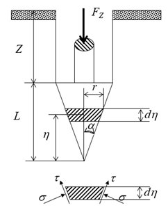
Figure 1 shows the schematic version of indenting the conical portion of the penetrometer into the semi-space part of the soil.
Figure 1. Cone penetrometer operation diagram
A numerical representation of this process can be expressed as follows:
$C I=-C \cot \phi+\Theta \cdot \frac{24 G^m(\tan \alpha+\tan \phi)(1+\sin \phi) \tan \alpha}{d^2 \gamma^2(m-2)(m-3)(3-\sin \phi) \tan ^3 \phi}$ (3)
where, Θ and m are factors taking into account the angle of internal friction.
$\Theta=\{C+(Z+L) \cdot \gamma \operatorname{Tan} \varphi\}^{3-m}-\{C+Z.$$\gamma \operatorname{Tan} \varphi\}^{2-m} \cdot\{C+(Z+3 L-L m) \cdot \gamma \tan \varphi\}$ (4)
$m=\frac{4 \sin \phi}{3(1+\sin \phi)}$ (5)
where, d is the width of the penetrometer’s cylindrical part, L is the length of the penetrometer's cone part, Z is the depth of the penetrometer's cylindrical part, α is the angle of the cone's sharpness.
A series of random values such as soil porosity and soil consistency factors were generated to account for soil parameters and cone index. The E and CI values were then compared when the deformation modulus ranged from 0...3 MPa and 0...2 MPa for forest and wetland soils, respectively, in increments of 250 kPa.
The above equation is verified for partial cases - different forest and waterlogged soils, clays, and loams.
In this study, a penetrometer with the following readings was used:
2.3 Study of soil parameters affecting recovery
This experiment used 100 soil samples from different forest zones in Arkhangelsk. Moisture content was measured by the thermostatically controlled weight method. To this end, a 20 cm long drill bit with a diameter of 4 cm was employed. Samples were placed in aluminum beakers and dried at 105℃. Soil temperature at this depth was measured using a TPV-50 mercury thermometer.
The time of forest soil recovery was analyzed based on some of its characteristics. The results showed that soil moisture content ranges within 30% to 60% and temperature within –5℃ to 25℃. Also, the following properties of soils were measured: Deformation modulus, shear modulus, internal friction angle, and specific coupling. It was established that the time of soil recovery depends on its temperature (T, ℃), moisture content (W, %) and deformation modulus (E, MPa) with a high correlation ratio (R2=0.8660):
$t_r=0.039 W^{1.42} T^{-0.27} E^{-0.21}$ (6)
Hence, the recovery time of the soil increases with the increasing percentage of moisture content and decreasing deformation modulus and temperature. The interaction between the forwarder and the forest soil was modeled using the above formula.
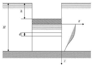
2.4 Modeling the forwarder indentation into the bearing surface
A schematic representation of this process, taking the soil as a half-space with a homogeneous texture, is provided in Figure 2.
Figure 2. Experimental diagram of the indentation process
Based on the above, the modulus of soil deformation can be determined:
$E=\frac{\sigma}{\varepsilon}$ (7)
where, σ is the regular soil condition and ε is the relative soil deformation.
Soil stresses are distributed according to the law of attenuation:
$\sigma=\frac{J p}{1+(z / a b)^2}$ (8)
where, J is the forwarder indentor factor relative to its size; p is the pressure exerted on the soil surface by indentor; z is the counted vertical coordinate; a is the criteria of deformed layer thickness; b is the indentor width.
Considering the initial height of the elementary soil layer as z0, its height in compression is:
$d z=(1-\varepsilon) d z_0$ (9)
During compression:
$d h_L=\varepsilon d z_0$ (10)
Based on these equations, compression can be calculated as follows:
$d h_L=\frac{\sigma}{E-\sigma} d z$ (11)
Then overall deformation is calculated by the following formula:
$h_L=\int_0^{H-h_L} d h_L$ (12)
The deformation modulus varies for each soil level according to a linear law, which will be considered as the first iteration:
$E=a_0+a_1 z$ (13)
where, a0, a1 are linear function coefficients:
$\left\{\begin{array}{c}a_0=E_1 \\ a_1=\frac{E_2-E_1}{H}\end{array}\right.$ (14)
where, E1and E2 are the deformation modulus values at the soil surface and depth corresponding to the thickness of the deformed layer (H), respectively. All three variables are distributed according to the law of equal density in the range from 0.5 to 5 MPa for modulus and from 0.3 to 0.8 m for H.
Given the previous formula, the total deformation can be calculated as follows:
$h_L=\int_0^{H-h_L} \frac{(a b)^2 J p}{(a b)^2\left(a_0+a_1 z-J p\right)+a_1 z^3+a_0 z^2} d z$ (15)
This integral was solved using a sample of random values of deformation modulus for the soil surface at a certain depth corresponding to the thickness of the deformed layer and the thickness of this layer itself. The values ranged from 500 kPa to 5 MPa (for modulus) and 30 - 80 cm (for thickness).
Given that the modulus of deformation can vary according to a quadratic law, the following formula shall be considered:
$E=b_0+b_1 z+b_2 z^2$ (16)
where, b0, b1, and b2 are coefficients of the quadratic function:
$\left\{\begin{array}{l}b_0=E_1 \\ b_1=-\frac{3 E_1-4 E_2+E_3}{H} \\ b_2=\frac{2 \cdot\left(E_1-2 E_2+E_3\right)}{H^2}\end{array}\right.$ (17)
Then the formula for calculating the total deformation for this case is as follows:
$h_L=\int_0^{H-h_L} \frac{(a b)^2 J p}{z^2\left(b_0+b_1 z+b_2 z^2\right)+(a b)^2\left(b_0+b_1 z+b_2 z^2-J p\right)} d z$ (18)
In addition, the possibility of changing the deformation modulus according to the cubic law was considered:
$E=c_0+c_1 z+c_2 z^2+c_3 z^3$ (19)
where, с0, с1, с2, с3 are coefficients of the cubic function:
$\left\{\begin{array}{l}C_0=E_1 \\ c_1=-\frac{1}{2} \cdot \frac{11 E_1-18 E_2+9 E_3-2 E_4}{2 H} \\ c_2=\frac{9}{2} \cdot \frac{2 E_1-5 E_2+4 E_3-E_4}{H^2} \\ c_3=-\frac{9}{2} \cdot \frac{E_1-3 E_2+3 E_3-E_4}{H^3}\end{array}\right.$ (20)
Then the total deformation for such variant is:
$h_L=\int_0^{H-h_L} \frac{a^2 b^2 J p}{z^5 c_3+z_4 c_2+z^3\left(c_3 a^2 b^2+c_1\right)+z^2\left(c_2 a^2 b^2+c_0\right)+z c_1 a^2 b^2+a^2 b^2\left(c_0-J p\right)} d z$ (21)
Pressure at compression is calculated as follows:
$p=\frac{G_W k_d}{b l k_f}$ (22)
where, l is the length of forwarder indentor; kd and kf are coefficients of load dynamics and the shape of the contact pattern, respectively:
$k_f=0.8949 E^{-0.12}$ (23)
$k_d=\frac{l}{l+v t_{\mathrm{P}}}$ (24)
where, v is tractor driving speed.
Given the relationship between the compressive strain and the total deformation, we can find the total indentation:
$h=h_L \frac{p_S}{p_S-p}$ (25)
where, pS is an index of pressure that the soil can withstand without deformation:
$p_S=p_{S 0} \alpha_Z$ (26)
where, pS0 is the index of pressure that a soil layer with unlimited thickness can withstand without deformation, which depends on several factors, including the width and height of the indentor; αZ is the coefficient that takes into account the thickness of the deformable soil layer.
The value pS0 can be calculated as:
$p_{S 0}=0.5 K_1 B_1 N_1 \gamma b+N_2 \gamma h+K_3 B_3 N_3 C$ (27)
where, Kiis the factor that considers the shape of the contact pattern; Ni and S are coefficients that depend on the internal friction angle of the soil, and Bi is the factor that considers the angle of load application.
Indentor’s geometric parameters allow calculating coefficients Ki.
$K_1=\frac{l}{l+0.4 b}$ (28)
$K_3=\frac{l+b}{l+0.5 b}$ (29)
The values of Ni and S coefficients are calculated relative to φ:
$S=\tan \left(\frac{\pi}{4}-\frac{\phi}{2}\right)$ (30)
$N_1=\frac{1-S^4}{S^5}$ (31)
$N_2=\frac{1}{S^2}$ (32)
$N_3=\frac{2\left(1+S^2\right)}{S^3}$ (33)
Indentor load angle can be calculated as:
$\beta=\arctan \left(\frac{\tau}{p}\right) \pm \alpha$ (34)
where, α is the angle of rut slope and τ is the shear stress:
$\tau=\frac{j G}{t} \cdot \frac{t p \tan \phi+C t-C j}{j G+t p \tan \phi+C t-C j}$ (35)
where, t is the grouser pitch and j is the shear strain, which can be calculated by the formula obtained earlier:
$j=1.33 \sqrt{s^3 l}$ (36)
The value of the deformable layer thickness factor can be obtained as follows:
$\alpha_Z=1+\frac{H^* h}{2 H \cdot\left(H-h-0.25 H^*\right)}$ (37)
where, H* is the factor that depends on the internal friction angle and indentor width:
$H^*=\frac{\sqrt{2}}{2} \exp \left[\left(\frac{\pi}{4}+\frac{3 \phi}{4}\right) \tan \frac{3 \phi}{4}\right] b \cos \frac{3 \phi}{4} \tan \phi$ (38)
2.5 Passability conditions
Thus, considering all the parameters of the soil and forwarder, the conditions ensuring the tractor passability in all situations can be established:
(1) The rut depth must be below a specific critical value:
$h \leq h_{\text {crit }}$ (39)
The remaining conditions relate to forwarder characteristics.
(2) The factor value of resistance to tractor movement is equal to the ratio of rolling resistive force FR to the shear modulus:
$\mu_R=\frac{F_R}{G_W}$ (40)
In turn, the force depends on the indentor width and the pressure on the soil at a certain depth:
$F_R=\int_0^h b p d h$ (41)
Thus, the second condition is as follows:
$\mu_R M \leq N v$ (42)
(3) Sufficient level of traction on the soil should be ensured, i.e., the value of the tractive force, in this case, is non-negative:
$\mu_P \geq 0$ (43)
The force itself can be calculated as:
$\mu_P=\mu_T-\mu_R$ (44)
where, μT is a coupling factor:
$\mu_T=\frac{R_X}{G_W}$ (45)
(4) The forwarder must be capable of traversing an elementary unit of roughness with a certain height, which is calculated based on the tractive force value:
$h_{\Pi}=\frac{D}{2} \cdot\left(1-\frac{1}{\sqrt{1+\mu_p^2}}\right)$ (46)
Given that the thickness of the deformable layer during passage is limited, the relative compaction of the soil can be determined:
$\xi=\frac{\gamma_P}{\gamma}=1+\frac{h_L}{H}$ (47)
where, γP is the specific weight of soil after tractor passage.
If uneven compaction of the soil shall be considered, the equation is reduced to the following form:
$d \xi=1+\frac{1}{H} d h_L$ (48)
2.6 Software implementation of models
All model codes were written and compiled in the Maple 2015 software language. The first step implies entering the known characteristics (γ, W, IL, CI, α, e, T, H) of the soil and calculating the missing ones (E, C, φ, G) based on the CI value. Also, knowing the E value, CI, C, φ, G can be calculated.
The equivalent deformation modulus was used to calculate inhomogeneous surfaces for three cases of dependence on depth (linear, quadratic, and cubic) using two, three, and four values of given factors, respectively.
The parameters of different soil types (sandy, clayey, and loamy soils) were calculated according to the established formulas for calculating E, C, φ, G, CI.
Besides, the written code considers the characteristics of the forwarder: D, B, S, HT, PW, GW, t, km, v, which are compared with critical values.
All calculations are repeated as many times as necessary to obtain optimal results.
The value ranges of parameters used to run the code and generate indicators are shown in Table 3.
Table 3. Variances of working model parameters
|
Parameter |
Range of variance and units of measurement |
|
E |
0.4-3.5 MPa |
|
S |
0.05-0.3 b/r |
|
B |
0.4-0.8 m |
|
D |
1.2-1.8 m |
|
pW |
0.15-0.55 MPa |
|
GW |
15-55 kN |
|
α |
1-30о |
|
m |
0.25-0.55 b/r |
|
t |
0.1-0.3 m |
|
HT |
0.4-0.8 m |
|
v |
1-5 km/h |
The process of cyclic soil loading was also modeled by considering the data obtained when generating values in each subsequent iteration and generating new values.
To compare the model's performance in this study, the WES model was applied.
2.7 Result accuracy assessment
For defining the level of reliability of the data obtained, an approximation was made using the least-squares method. In fact, the accuracy is indicated by the value of R2, which must be equal to 1 in the ideal condition of the system.
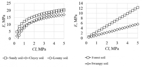
After processing the results based on Formula 6, a series of dependencies of the deformation modulus on the cone index has been established. The results are presented in Table 4 and Figure 3.
Table 4. Formulas of Е and CI correlations
|
Soil type |
Formula |
R2 |
|
Sandy soil |
E=12.151+5.240lnCI |
0.8991 |
|
Clayey soil |
E=8.914+5.019lnCI |
0.8267 |
|
Loamy soil |
E=7.583+7.521lnCI |
0.9832 |
|
Forest soil |
E=2.4713CI |
0.9993 |
|
Swampy soil |
E=1.1315CI |
0.9987 |
Figure 3. Graphical representation of the relationship between modulus of deformation and cone index
Analysis of the dependence of soil parameters on its compaction degree (ξ) allowed approximating the results and providing them in the formulaic form:
$E_R=-0.483 \cdot\left(A_{b E}+B_{b E} I_L\right) \cdot(\xi-1)+1$ (49)
$C_R=-0.483 \cdot\left(A_{b C}+B_{b C} I_L\right) \cdot(\xi-1)+1$ (50)
$\phi_R=-0.483 \cdot\left(A_{b \phi}+B_{b \phi} I_L\right) \cdot(\xi-1)+1$ (51)
During the processing of the soil porosity and consistency factors data, strongly correlated formulas for the calculation of soil parameters were established:
$C=\left(21.6-8.26 I_L\right) \cdot e^{-0.898-0.123 I_L}\quad\left( R^2=0.9331\right)$ (52)
$\phi=\left(16.0-1.41 I_L\right) \cdot e^{-0.203-0.0113 I_L} \quad\left( R^2=0.8771\right)$ (53)
$G=\left(5.12-1.89 I_L\right) \cdot e^{-1.39+0.0496 I_L} \quad\left( R^2=0.9385\right)$ (54)
$C I=\left(1.03-0.517 I_L\right) \cdot e^{-1.11-0.0797 I_L} \quad\left( R^2=0.8952\right)$ (55)
Approximation of the results revealed that these parameters could be provided as following dependencies:
$E_R=\left(0.599-0.151 I_L\right) \cdot(\xi-1)+1$ (56)
$C_R=\left(0.434-0.0594 I_L\right) \cdot(\xi-1)+1$ (57)
$\phi_R=\left(0.098-0.00546 I_L\right) \cdot(\xi-1)+1$ (58)
$G_R=\left(0.671-0.024 I_L\right) \cdot(\xi-1)+1$ (59)
$C I_R=\left(0.536+0.0385 I_L\right) \cdot(\xi-1)+1$ (60)
Further evaluation of the results in terms of dependency of the physical and mechanical properties of the soil on deformation modulus:
$C=12.066 E^{0.8159}\left(R^2=0.9659\right)$ (61)
$\phi=14.078 E^{0.1816}\left(R^2=0.8471\right)$ (62)
$G=2.0893 E^{1.1371}\left(R^2=0.9763\right)$ (63)
$C I=0.5004 E\left(R^2=0.8756\right)$ (64)
And cone index:
$E=1.961 C I\left(R^2=0.8727\right)$ (65)
$C=18.116+3.0203 C I\left(R^2=0.9361\right)$ (66)
$\phi=3.8847+12.049 C I\left(R^2=0.9296\right)$ (67)
$G=4.4207 C I\left(R^2=0.9227\right)$ (68)
After integrating Eq. (63), it follows:
$h_L=\frac{\operatorname{Jpabarctan}\left(\frac{E\left(H-h_L\right)}{a b \sqrt{E(E-J p)}}\right)}{\sqrt{E(E-J p)}}$ (69)
where, J and a are factors of equation:
$J=\frac{0.03 b+l}{0.6 b+0.43 l}$ (70)
$a=\frac{0.64 H+0.64 b}{H}$ (71)
where, b and l are width and length of the equivalent forwarder’s indentor, respectively:
$b=B+\frac{10 h \cdot h_Z}{1-h+H_T-h_Z}$ (72)
$l=\sqrt{D h_z-h_Z^2}+\sqrt{D \cdot\left(h_z+h\right)-\left(h_z+h\right)^2}$ (73)
where, the radial deformation of the tire obtained by approximating the experimental results with a high accuracy degree (R2=0.9775):
$h_Z=0.0715 G_W^{0.691} B^{0.305} P_W^{-0.677}$
$D^{-0.394} h^{-0.0891 P_w^{0.193} D^{0.558} G_W^{-0.201} B^{-0.0574}}$ (74)
Integrating the right part of the formula (55) results in a cumbersome expression that is convenient neither for analysis nor for practical use.
The calculation results based on Eq. (54) with taking account of generated values show the dependence of the equivalent modulus of deformation on the system factors with a high accuracy degree (R2=0.9773):
$E_{\text {equiv }}=0.95 a_0+0.45 a_1 H$ (75)
The calculation results based on Eq. (59) for the same values of modulus deformation and thickness of the deformed layer show the following dependence with accuracy R2=0.9094:
$E=0.966 b_0+0.0191 b_0 b_1+0.00396 b_0 b_2$$+0.229 b_1 H+0.0543 b_2 H$ (76)
The calculation results based on Eq. (63) with taking account of generated values of modulus and layer thickness allow providing the cubic change in the deformation modulus as the following dependence, where R2=0.9552:
$\begin{aligned} E=1.05 c_0+ & 0.124 c_1+0.023 c_2-0.0103 c_3-0.0000139 c_0 c_1 c_2-0.0000151 c_0 c_1 c_3 \\ & -0.00000141 c_0 c_2 c_3-0.0325 c_0 c_1 H+0.0189 c_0 c_2 H+0.00762 c_0 c_3 H \\ & -7.54 \cdot 10^{-9} c_1 c_2 c_3+0.000183 c_1 c_2 H-0.00000738 c_2 c_3 H-0.109 c_0 H \\ & +0.000212 c_1 c_2+0.00023 c_1 c_3+0.092 c_1 H+0.0000157 c_2 c_3 \\ & +0.0727 c_2 H+0.0412 c_3 H\end{aligned}$ (77)
Then, in the case of linear variability in deformation modulus, the equation for calculating total deformation can be as follows:
h=$\frac {J p_S p a \arctan \left(\frac{E\left(H p-h\left(p_S-p\right)\right)}{a b p \sqrt{E(E-J p)}}\right)} {\left(p_S-p\right) \sqrt{E(E-J p)}}$ (78)
If non-uniform bearing surfaces are impacted, then equivalent modules shall be used (formulas 57, 61, 65).
As a result, dependencies h, μR, μT on soil and forwarder parameters were obtained:
$h=\frac{0.000479 p_w^{0.186} G_W^{1.544} \alpha^{0.0618} t^{0.0472} H_T^{0.0414}}{E^{1.637} S^{0.0325} B^{2.197} D^{0.652} v^{0.0338}}$ $\left(R^2=0.9660\right)$ (79)
$\mu_R=\frac{0.00342 p_w^{0.299} G_W^{1.171} \alpha^{0.0589} t^{0.0485} H_T^{0.0318}}{E^{1.242} S^{0.0299} B^{1.898} D^{1.0658} m^{0.0302} v^{0.0471}}$ $\left(R^2=0.9719\right)$ (80)
$\mu_T=\frac{0.385 E^{0.486} B^{0.110} t^{0.132}}{S^{0.128} G_w^{0.0711} m^{0.266} v^{0.00980}}$ $\left(R^2=0.9531\right)$ (81)
As seen, the level of determination exceeds 95%, which the high accuracy of approximations and the possibility of its practical application, as shown further.
The last two formulas allow simplifying the process of determining the tractive force:
$\mu_T=1.5605 p_S-1.1708 h+0.2004$ (82)
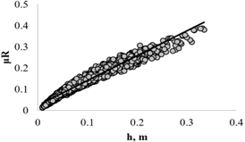
The dependence of the tractor's resistive force on the rut depth is shown in Figure 4.
Figure 4. Graphical representation of the dependence $\mu_R$ on h
As follows, there is a linear dependence between these indicators with the accuracy of R2=0.9578, which can be represented as:
$\mu_R=1.1798 h+0.0229$ (83)
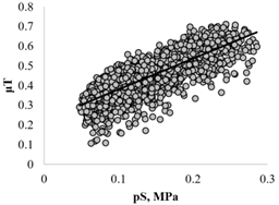
The dependence of the coupling factor on the soil bearing capacity is shown in Figure 5:
Figure 5. Graphical representation of the dependence $\mu_T$ on pS
As seen, the degree of dependence is much lower than in the mathematical model and amounts to (R2=0.6672). The dependence function can be as follows:
$\mu_T=1.5605 p_S+0.2233$ (84)
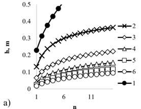
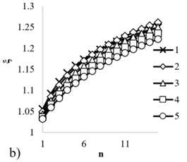
The results of multiple impacts on the soil are shown in Figure 6.
Figure 6. Variation of soil parameters: a) rut depth and b) relative inclination after multiple tractor’s passes at different values of modulus of deformation: 1-E=1 MPa; 2-E=1.5 MPa; 3-E=2 MPa; 4-E=2.5 MPa; 5-E=3 MPa
The figure shows that increasing ruts depth and lack of soil stabilization (high compaction values) are typical of weak soils. In the case of moderately resistant soils, deepening occurs up to a certain maximum value, while in the case of highly resistant soils, rutting is almost uncommon.
Furthermore, the obtained results allowed determining the dependence of rut depth and soil compaction on the number of passes and the strength of the soil with accuracy indicators of R2=0.9311 and R2=0.9363, respectively:
$h=0.906 h_{(1)} n^{0.447} E^{0.475}$ (85)
$\xi=1.0451 n^{0.0686} E^{0.0281}$ (86)
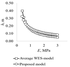
The results of comparing the proposed model's rut depth and tractive force and the existing WES model are shown in Figures 7 and 8.
Figure 7. Graphic representation of comparing results to determine rut depth
Figure 8. Graphical representation of comparing results to determine the tractive force
As shown above, the results are quantitatively and qualitatively consistent, demonstrating the effectiveness of the proposed model.
Papunin et al. [25] studied the issue of off-road vehicles of different tonnage. In the modeling process, the tractive force of the wheel, rolling resistance, air resistance, and other indicators were considered. The authors indicate that tire tread saturation affects the tractive force value, which is in line with the results of this study. They also indicate that the tire's width influences the size and camber of the rut. During the simulations, the tire's width was considered as it affects the soil parameters, which in turn affects the formation of ruts. Furthermore, they have shown that weak soils are much quicker to decompose.
This study has shown that an increase in tractor passes leads to higher soil compaction and deepening of the rut. The results of this experiment are consistent with the data of Lamandé et al. [26]. In either case, the maximum compaction occurs after the first passage and then decreases but does not stop completely.
A mathematical model for predicting tractors' passability was developed during the study. Its efficacy is demonstrated when used in the field and relative to another model.
Modulus of deformation and cone index are closely related linear function indicators. They can be interchangeable when calculating other soil parameters, such as specific coupling, angle of internal friction, and shear modulus.
Observations have shown that in sandy, loamy and clayey soils, compaction characteristics change linearly in soil surface homogeneity. For heterogeneous soils, the value of the equivalent deformation module may be used, thus simplifying the calculations. Also, these soils are characterized by additional dependencies of the deformation module during the deepening of compaction: square and cubic.
Study findings have shown that drier and warmer soils are much faster to deform, as the modulus of their deformation is relatively high.
The developed model is consistent with the existing model and takes account of the following soil parameters: the type, modulus of deformation and shear, slope angle, specific weight, consistency, porosity, temperature, moisture, the thickness of the deformation layer; and the forwarder parameters: Width and height of the wheel, tractor driving speed, tire tread expression and internal pressure in them.
The model also predicts the extent of soil compaction and rutting depth after multiple tractors passages.
Therefore, the proposed model can be used to analyze the extent of the impact of forestry and agricultural tractors on soils.
The study was carried out within the confines of the scientific school "Advances in lumber industry and forestry". The underlying content of this paper was supported by the grant of the Russian Science Foundation No. 22-26-00009, https://rscf.ru/project/22-26-00009/
[1] Boikov, V.P., Guskov, V.V., Pavarekha, A.S. (2021). Automated tire pressure control system for multi-purpose wheeled vehicles. Science and Technique, 20(1): 33-36. https://doi.org/10.21122/2227-1031-2021-20-l-33-36
[2] Ding, L., Gao, H., Deng, Z., Nagatani, K., Yoshida, K. (2011). Experimental study and analysis on driving wheels' performance for planetary exploration rovers moving in deformable soil. Journal of Terramechanics, 48(1): 27-45. https://doi.org/10.1016/j.jterra.2010.08.001
[3] Yamashita, H., Jayakumar, P., Alsaleh, M., Sugiyama, H. (2018). Physics-based deformable tire–soil interaction model for off-road mobility simulation and experimental validation. Journal of Computational and Nonlinear Dynamics, 13(2): 021002. https://doi.org/10.1115/1.4037994https://doi.org/10.1115/1.4037994
[4] Riggert, R., Fleige, H., Horn, R. (2019). An assessment scheme for soil degradation caused by forestry machinery on skid trails in Germany. Soil Science Society of America Journal, 83: S1-S12. https://doi.org/10.2136/sssaj2018.07.0255
[5] Rego, G.E., Grigoreva, O.I., Voronov, R.V. (2021). Algorithms for calculating schemes of transport routes in a felling area. In: IOP Conference Series: Earth and Environmental Science, Vol. 806, No. 1, p. 012025. https://doi.org/10.1088/1755-1315/806/1/012025
[6] Engler, B., Hoffmann, S., Zscheile, M. (2021). Rubber tracked bogie-axles with supportive rollers–a new undercarriage concept for log extraction on sensitive soils. International Journal of Forest Engineering, 32(1): 43-56. https://doi.org/10.1080/14942119.2021.1834814
[7] Rudov, S., Shapiro, V., Grigorev, I., Kunitskaya, O., Druzyanova, V., Kokieva, G., Filatov, A., Sleptsova, M., Bondarenko, A., Radnaed, D. (2019). Specific features of influence of propulsion plants of the wheel-tyre tractors upon the cryomorphic soils, soils, and soil grounds. International Journal of Civil Engineering and Technology, 10(1): 2052-2071. https://iaeme.com/MasterAdmin/Journal_uploads/IJCIET/VOLUME_10_ISSUE_1/IJCIET_10_01_186.pdf, accessed on Jan. 17, 2015.
[8] Vennik, K., Keller, T., Kukk, P., Krebstein, K., Reintam, E. (2017). Soil rut depth prediction based on soil strength measurements on typical Estonian soils. Biosystems Engineering, 163: 78-86. https://doi.org/10.1016/j.biosystemseng.2017.08.016
[9] Rudov, S.E., Kunitskaya, O.A. (2020). Theoretical studies of ecological compatibility of wheeled forest machines and permafrost soils in forests cryolithic zone. In: Transport and transport-technological systems. Materials of the International Scientific and Technical Conference, pp. 323-326.
[10] Khitrov, E.G., Andronov, A.V., Khakhina, A.M., Grigoryev, G.V. (2020). Mathematical models of the interaction of machine engines with soils (review). Resources and Technology, 17(4): 15-65. https://doi.org/10.15393/j2.art.2020.5422
[11] Nordfjell, T., Öhman, E., Lindroos, O., Ager, B. (2019). The technical development of forwarders in Sweden between 1962 and 2012 and of sales between 1975 and 2017. International Journal of Forest Engineering, 30(1): 1-13. https://doi.org/10.1080/14942119.2019.1591074
[12] Tchernyshev, N.I., Sysoev, O.E., Solovev, D.B., Kiselyov, E.P. (2018). Basic robotecnical platform for implementation of accurate farming technologies. Bulletin of Electrical Engineering and Informatics, 7(4): 522-528. http://dx.doi.org/10.11591/eei.v7i4.920
[13] Galiullin, L.A., Valiev, R.A. (2017). Diagnostics technological process modeling for internal combustion engines. In: 2017 International conference on industrial engineering, Applications and Manufacturing (ICIEAM), pp. 1-4. https://doi.org/10.1109/ICIEAM.2017.8076124
[14] Rudov, M.E., Kunitskaya, O.A., Grigoriev, M.F., Stepanova, D.I., Grigorieva, A.I. (2020). Ecological and silvicultural aspects of forest machines in the cryolith-zone forests. Actual Problems of Forest Complex, 57: 14-17.
[15] Grigorev, I., Kunickaya, O.G., Tikhonov, E., Hertz, E., Khakhina, A., Burmistrova, O., Sukhomlinova, N., Zhuk, A. (2021). Methodology for assessing and managing the environmental performance of skidding and feller buncher tractors. Forests, 12(12): 1723. https://doi.org/10.3390/f12121723
[16] Klubnichkin, V.E., Klubnichkin, E.E., Naumov, V.N. (2018). Improvement of bogie tracks for forestry wheeled vehicles. In: IOP Conference Series: Materials Science and Engineering, Vol. 386, No. 1, p. 012015. https://doi.org/10.1088/1757-899X/386/1/012015
[17] Pillinger, G., Géczy, A., Hudoba, Z., Kiss, P. (2018). Determination of soil density by cone index data. Journal of Terramechanics, 77: 69-74. https://doi.org/10.1016/j.jterra.2018.03.003
[18] Sunusi, I.I., Zhou, J., Wang, Z.Z., Sun, C., Ibrahim, I.E., Opiyo, S., Korohou, T., Soomro, S.A., Sale, N.A., Olanrewaju, T.O. (2020). Intelligent tractors: Review of online traction control process. Computers and Electronics in Agriculture, 170: 105176. https://doi.org/10.1016/j.compag.2019.105176
[19] Grigorev, I., Kunickaya, O., Burgonutdinov, A., Ivanov, V., Shuvalova, S., Shvetsova, V., Stepanishcheva, M., Tikhonov, E. (2020). Theoretical studies of dynamic soil compaction by wheeled forestry machines. Diagnostyka, 21: 3-13. https://doi.org/10.29354/diag/127650
[20] Kunickaya, O.G., Hertz, E., Kruchinin, I., Tikhonov, E., Ivanov, N., Dolmatov, N., Zorin, M., Grigorev, I. (2021). Pressure control systems for tyre preservation in forestry machinery and forest soils. Asian Journal of Water, Environment and Pollution, 18(3): 95-102. https://doi.org/10.3233/AJW210033
[21] Naumov, V.N., Mashkov, K.Y., Byakov, K.E. (2019). Automatic determination of soil parameters by robotic vehicles. In: Journal of Physics: Conference Series, Vol. 1177, No. 1, p. 012016. https://doi.org/10.1088/1742-6596/1177/1/012016
[22] Dobretsov, R.Y., Sokolova, V.A., Teterina, I.A., Malyukov, S.V., Aksenov, A.A., Smertin, N.V. (2021). Interaction feature of caterpillar tracks with soil under significant axial displacements of pressure center. In: IOP Conference Series: Earth and Environmental Science, Vol. 839, No. 5, p. 052023. https://doi.org/10.1088/1755-1315/839/5/052023
[23] Khakhina, A.M., Grigoryev, I.V. (2017). Analysis of foreign mathematical models of interaction of forest machine engines with the driving surface. Actual Directions of the XXI Century Scientific Research: Theory and Practice, 5(10): 548-551.
[24] Amosov, A.G., Mirolyubova, T.I. (2022). Review of methods for calculating the cross-country ability of heavy road trains in off road conditions. Transportation Research Procedia, 61: 206-212. https://doi.org/10.1016/j.trpro.2022.01.034
[25] Papunin, A.V., Belyakov, V.V., Makarov, V.S. (2020). The study of the profile passability all-terrain vehicles with a wheel formula 6x6 full mass 0.3, 0.75, 2 tons. In: IOP Conference Series: Materials Science and Engineering, Vol. 709. No. 4, p. 044029. https://doi.org/10.1088/1757-899X/709/4/044029
[26] Lamandé, M., Greve, M. H., Schjønning, P. (2018). Risk assessment of soil compaction in Europe–Rubber tracks or wheels on machinery. Catena, 167: 353-362. https://doi.org/10.1016/j.catena.2018.05.015