Kakei A. Ayad* | Abdolbaqi Mohammed Khdher | Kamal Jalal Tawfeeq Albazzaz | Amer Najat Najmaldeen Kakahy | Ali Hussein Abdulkarim | Jayantha Epaarachchi
© 2022 IIETA. This article is published by IIETA and is licensed under the CC BY 4.0 license (http://creativecommons.org/licenses/by/4.0/).
OPEN ACCESS
In recent years, researchers have paid special attention to wall uniformity temperature and improvement in a micro-combustor (MC) for applications as thermos-photovoltaic (TPV) since they have a direct influence on feasibility and efficiency of the required conversion of energy. Numerous experimentation and numerical studies in the field of micro-combustion have been carried out and published in this respect. This study focuses on the flame and flow behaviour in an improved MC. Utilizing the famous approach of fluid dynamics being computational (CFD), the impact of geometrical flow parameters behaviour and temperature of wall is explored and measured. The generated model is being used to evaluate the effects of Hydrogen (H) mass flow rate (MFR) and H/air equivalency ratios on the flame pattern and outer temperature of wall of conventional and enhanced MCs. Moreover, the influence of various MC cross sections (CS), such as square, circular, and flat, on temperature of wall is examined. The findings reveal that when the MFR rises, the wall outside temperature rises as well. The MC with flat cross-sections (CSs) is found to be more effective in terms of power of emitter and efficiency of emitter.
micro thermo-photovoltaic (MTPV), micro flat tube combustor, combustion characteristic
Recently, the engineering industry has showed more interest to use fossil fuel to power micro devices as a consequence of the latest advancements in micro manufacturing capabilities. Micro-power productions have been applied in many different engineering applications, for instance, rovers, actuators, sensors, robotics, portable electric appliances, and many more due to its high energy density and low cost [1, 2]. Since Epstein and Senturia [3] have shown a great potential a scaling down traditional generator of gas turbine, several micro-power technologies were prototyped i.e., micro-thermo photovoltaic (MTPV) systems, micro-fuel cells, micro-gas turbines, and different devices.
Nevertheless, low efficiency of energy conversion [4, 5] and instability of combustion [6, 7] are significant issues of the micro-thermophotovoltaic (MTPV) system's application remains. Consequently, several sophisticated processes and methods have been developed and applied, including catalytic combustion [8, 9]. Ran et al. [8] studied the catalytic combustion characteristics of methane in micro-channels with a concave and convex cavity, respectively, In the micro-channel with convex wall cavity, the inner wall pressure increases, because the fuel is disrupted when it flows through the cavity. Then the mixture of methane contact with catalyst is enhanced, which favors the combustion of methane. The recirculation zone which is the largest area formed in the micro-channel with convex wall cavity absorbs more high temperature gas and raises the combustion temperature. Heat transfer in the convex micro-channel is enhanced which makes the temperature distribution more uniform. Moreover, Jiaqiang et al. [9] investigated a micro combustor with a backward-facing step and unique inlet shape to enhance the mixing performance and flame stabilization. The results indicate that the homogeneous reaction is obviously weakened in the catalytic combustor, but a higher and more uniform outer wall temperature is obtained, and the outer wall temperature difference can be decreased by up to 28%. The flow characteristics of gaseous mixture in the catalytic combustor are better than those in the non-catalytic combustor.
Combustion of porous media [10, 11], combustion of bluff-body [12-14], method of external heating [15], besides the field being electrical [16]. As a consequence, the associated study findings revealed that these techniques significantly increase the limit of blow-off [17, 18], thermal function [19, 20], and emissions combustion [21, 22]. However, a typical micro TPV system is shown in Figure 1 involves 3 prime components: An emitter, a fuel source, and a TPV cell array. Yang et al. [23, 24] were among the first to create an MTPV prototype for the purpose of power generation.
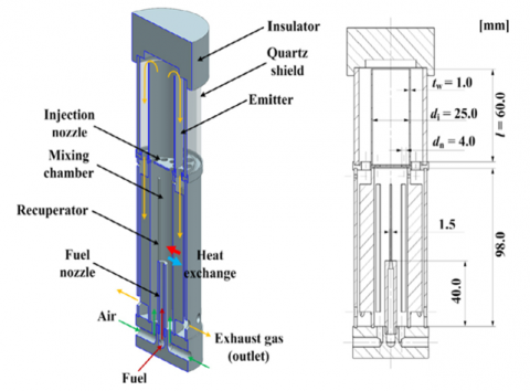
It is noteworthy that a MTPV's energy conversion efficiency may be enhanced by attaining a uniform and higher temperature of wall. In addition, it can be improved through combustion being continuous inside the combustor producing substances with extremely low energy of the band gap. The thermal performance of MCs, which has a substantial impact on the energy MTPV conversion effectiveness systems, must be prioritized among the abovementioned performance parameters. recirculation of heat, for illustration, is a valuable technique because of its recirculation of heat structure; as a result, the Swiss-roll combustor demonstrated high thermal performance [25, 26]. Tang et al. [27] planned and implemented a heat-recirculated planar combustor and the experimental data show that a recirculation of heat combustor has the radiation efficiencies greatly superior to a combustor of straight channel. Kim et al. [28] planned the developed combustor of heat-recirculating with several injectors. Furthermore, the structure of this combustor is shown in Figure 1. The findings expose that the developed numerous injectors combustor improves the efficacy of maintain and can also consistently heat transfer for an extended period of time.
Figure 1. Configuration of heat-recirculating combustor with multiple injectors [28]
Jiang et al. [29] have built a two optimized baffles planar combustor. The results show that the planar combustor with baffles was demonstrated to reach a high temperature of wall with improved uniformity. AMC with inner winding fins for thermo-photovoltaic systems has been investigated to improves heat transfer and energy efficiency [30]. The results demonstrate that at a 5 m/s input velocity, the MC with eight winding fins has the maximum efficiency of energy (66.9%). The calculated energy efficiency is 6.9% higher than the traditional one. A mixed baffle and bluff geometry planar MC was inspected by Ansari et al. [31]. The most significant design parameter affecting distribution of temperature and homogeneity was found to be baffle thickness.
The micro-cylindrical combustor (MCC) including a rib as rectangular was enhanced by Zuo et al. [32] and comparing it with typical MCC. The rib was designed for recirculation of heat within the back half of the wall of combustor. The comparison showed that the MCC with rib as rectangular exhibited bigger and more uniform distribution of temperature of wall than the typical MCC. Furthermore, the structure of cavity has improved significantly and effectively. The flame is near to the wall of combustor due to the divided walls, which improves heat transfer. In addition, Akhtar et al. [33] studied the influence of CS on the temperature of wall of combustors as micro-tube. Thermal performance was demonstrated to be superior in trapezoidal and triangular CSs. Zuo et al. [34] established a combustor of micro-elliptical tube and comprised to combustor of micro-circular tube. The micro-elliptical tube combustor showed lot of thermal performance potential.
As shown, many trials and computational revisions have been presented to examine the properties of combustion of MCs under various different conditions. In this study, improved micro-square, circular, and flat tube combustors are constructed. In addition, the combustion properties of the micro flat tube and square combustors are widely explored. Moreover, micro-flat tube and square combustors are compared with the combustor of micro-circular tube at varied H/air equivalency ratios and $\dot{m} H_2$ MFRs. Moreover, the impact of geometries being distinctive on the general energy transformation of MTPV efficiency was investigated to determine the combustor of micro-elliptical tube benefits and drawbacks. The aims of this work are as follows: First, to create and evaluate a three-dimensional model for enhanced circular CS MC performance utilizing Zuo et al. [35] data for validation; second, to look into the effects of several CS shapes of MC, such as flat, square, and circular, on distribution of temperature over the wall of combustor and the flame structure; and third, to evaluate the efficiency of emitter and power for various CSs of MC.
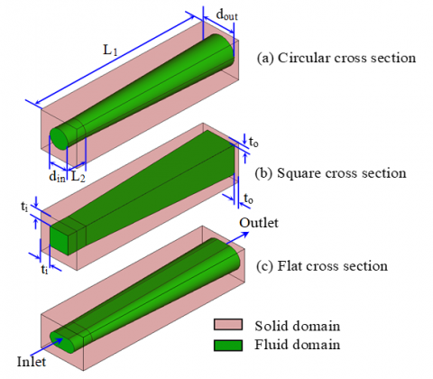
This study was implemented on an increased single MC channel in Zuo et al. [35] study's as shown in Figure 2 (a) The three single MCs channel have the same overall size. The three single MCs channel' total length, wall thickness from the input side, and wall thickness from the outlet side are 18 mm, 1 mm, and 0.5 mm, correspondingly. The three single MCs channels have the same inlet hydraulic diameter (d1) and outlet hydraulic diameter (d2), measuring 2mm and 3mm, respectively. As well as, the chamber of combustion’s internal diameter is first held constant until z=L2 (L2=2 mm), then progressively enlarged from 2 - 3 mm as the coordinate of axial z is enlarged from 2 - 18 mm.
Figure 2. Computational analysis field of (a) circular, (b) square, (c) flat CS
2.1 Mathematical model
Prior to solve the mathematical combustion model, mass, and transport of heat in micro-combustion channels, the following assumptions are made:
(a) The Knudsen O2 and H2 number is significantly lower compared to the value being critical as the H/air combination is supposed a continuum, (b) The mixture of H/air is considered uniform, (c) The final combustion status may be determined utilizing a steady solver, (d) The exterior wall's radiation and convection are considered, while the radiated gas in the chamber of combustion is not, (e) Convection and radiation between the exterior wall and the surroundings are studied, whereas gas radiation is omitted in the chamber of combustion, (f) In the combustion channels, there are no reactions of surface. Finally, the leading formulas are as following, based on mass, momentum, energy, and conservation of species:
Continuity formula
$\nabla \cdot(\overrightarrow{\rho v})=0$ (1)
where, $\vec{v}$=vector of velocity and ρ=gas density.
Formula of momentum conservation
$\rho(\vec{v} \cdot \nabla \vec{v})=-\nabla p+\nabla \cdot\left(\mu\left[\nabla \vec{v}+(\nabla \vec{v})^T-\frac{2}{3} \nabla \cdot \vec{v} I\right]\right)$ (2)
where, μ=viscosity being molecular, p=gas absolute pressure, and I=tensor unit.
Formula of conservation of energy
$\nabla \vec{v}\left(\rho E_f+P\right)=\nabla \cdot\left[k_{e f f} \nabla T-\left(\sum_j h_j \overrightarrow{D_j}\right)+(\mu[\nabla \vec{v}+\right.$
$\left.\left.\left.(\nabla \vec{v})^T-\frac{2}{3} \nabla \cdot \vec{v} I\right]\right) \cdot \vec{v}\right]+S_f^h$ (3)
where, T=temperature, Ef=total energy fluid, $\overrightarrow{D_{\jmath}}$ =diffusion species flux=j, hj=species enthalpy=j, $S_f^h$ =fluid source of enthalpy term, and keff=effective conductivity.
Formula of wall conservation of energy
$\nabla \cdot\left(k_w \cdot \nabla \mathrm{T}\right)=0$ (4)
where, kw=thermal wall conductivity.
Formula of conservation of species
$\nabla\left(\rho \vec{u} Y_j\right)=-\nabla \overrightarrow{D_J}+R_j$ (5)
where, Yj=species fraction mass, j and Rj=net production rate of species j by chemical reaction.
Between the environment and the outer wall of combustor, the total energy Qloss is defined:
$Q_{\text {loss }}=h_0 \sum A_{w, i}\left(T_{w, i}-T_0\right)+\varepsilon \sigma \sum A_{w, i}\left(T_{w, i}^4-\right.$$\left.T_0^4\right)$ (6)
where, the constant of Stephan-Boltzmann is (σ=5.67×10⁻⁸ W/(m2·K4)), the natural coefficient convection of transfer of heat is h0=10 W/(m2·K), the temperature as ambient, is T0=300 K, and ε is 0.85 for Steel material [3]. Furthermore, the outer temperature of wall variance $\Delta T_w$ and the mean temperature of wall $\bar{T}_w$ [34] are defined:
$\bar{T}_w=\frac{\sum A_{W, i} T_{W, i}}{\sum A_{W, i}}$ (7)
$\Delta T_W=T_{W, \max }-T_{W, \min }$ (8)
where, Tw,i is the outer grid cell temperature of wall i, $\bar{T}_w$ is the mean temperature of wall, and Aw,i is the outer wall surface grid cell area i. Tw,max is the outer maximum wall temperature, and Tw,min is the outer minimum wall temperature.
The efficiency of combustor of MCs emitter and the total power of radiation Pem may be measured as following:
$\eta_{\text {combustor }}=\frac{P_{e m}}{\dot{m}_{H_2} Q_{L H V}} \times 100 \%$ (9)
$P_{e m}=\varepsilon \sigma \sum A_{w, i}\left(T_{w, i}^4-T_o^4\right)$ (10)
QLHV is the Hydrogen lower heating, 119.96 MJ/kg [34] and $\dot{m}_{H_2}$ is the H2 inlet MFR.
2.2 Computation analysis
Fluids can be considered as continuums as long as the combustor chamber's characteristic size stays larger than the gas flow through the MC’s molecular mean-free path. The structural characteristic of the new shape of MC is numerically investigated with three-dimensional model. The computational domain of the studied case is illustrated in Figure 3. The MC geometries were drawn and meshed utilizing Gambit 2.3.6. For calculating the momentum, mass, energy, and conservation of species formulas, along with conjugated conduction of heat in walls being solid, the commercial program FLUENT 6.3.2 was chosen. The standard k-model is applied in the viscous model panel to simulate flow behaviour when the cold flow's Reynolds number hits 500 [36, 37]. A typical H/air chemical process confirmed by Yang et al. [38] is employed for combustion behaviours representation in the species model panel, as shown in Table 1.
The volumetric reactions are taken into account, but the wall surface reactions are not. The turbulence-chemistry interaction is solved utilizing the dissipation conception of Eddy model. The mixture specific and density heat are determined in the material panel by utilizing the mixing-law and the law of incompressible-epitome-gas. The thermal and viscosity conductivity of the mixture are measured use the fraction-weighted mass mean approach. In the same way, the specific of every species heat is determined use a method of piecewise fitting polynomial. The piecewise fit is obtained by connecting each pair of consecutive data points with a straight line, using a degree-1 polynomial on each subinterval. Indeed, this is what Matlab’s plot command does by default with the arrays of x and y values that you give it. Table 2 shows the results. The pressure-velocity relationship is decoupled utilizing a coupled algorithm in the solution control panel. To estimate the leading formulas, a second-order exposed approach is utilized.
Table 1. (H/air) chemical kinetics for Nineteen Species and Nine Reactions as reported in [39]
|
No. |
Reaction |
Ar |
βr |
Er (J/kmol) |
|
1 |
O2 + H→OH + O |
5.10 × 10¹³ |
- 0.82 |
6.91 × 10⁷ |
|
2 |
H2+O→OH+H |
1.80 × 10⁷ |
1.00 |
3.70 × 10⁷ |
|
3 |
H2 + OH→H2O + H |
1.20 × 10⁶ |
1.30 |
1.52 × 10⁷ |
|
4 |
OH + OH→H2O + O |
6.00 × 10⁵ |
1.30 |
0.00 |
|
5 |
H2 + O2→OH + OH |
1.70 × 10¹⁰ |
0.00 |
2.00 × 10⁸ |
|
6 |
H+ OH + M→H2O+Ma |
7.50 × 10¹⁷ |
- 2.60 |
0.00 |
|
7 |
O2+M→O + O + M |
1.90 × 10⁸ |
0.50 |
4.001 × 10⁸ |
|
8 |
H2+M→H + H +Mb |
2.20 × 10⁹ |
0.50 |
3.877 × 10⁸ |
|
9 |
H+ O2+M→HO2+Mc |
2.10 × 10¹² |
- 1.00 |
0.00 |
|
10 |
H + O2 + O2→HO2 + O2 |
6.70 × 10¹³ |
-1.42 |
0.00 |
|
11 |
H + O2 + N2→HO2 + N2 |
6.70 × 10¹³ |
- 1.42 |
0.00 |
|
12 |
HO2 + H→H2 + O2 |
2.50 × 10¹⁰ |
0.00 |
2.90 × 10⁶ |
|
13 |
HO2 + H→OH + OH |
2.50 × 10¹¹ |
0.00 |
7.90 × 10⁶ |
|
14 |
HO2 + O→OH + O2 |
4.80 × 10¹⁰ |
0.00 |
4.20 × 10⁶ |
|
15 |
HO2 + OH→H2O + O2 |
5.00 × 10¹⁰ |
0.00 |
4.20 × 10⁶ |
|
16 |
HO2 + HO2→H2O2 + O2 |
2.00 × 10⁹ |
0.00 |
0.00 |
|
17 |
H2O2 +M→OH + OH + M |
1.30 × 10¹⁴ |
0.00 |
1.905 × 10⁸ |
|
18 |
H2O2 + H→H2 + HO2 |
1.70 × 10⁹ |
0.00 |
1.57 × 10⁷ |
|
19 |
H2O2 + OH→H2O + HO2 |
1.00 × 10¹⁰ |
0.00 |
7.50 × 10⁶ |
|
a Enhancement factors: H2O = 20.0. b Enhancement factors: H2O = 6.0, H = 2.0, and H2 = 3.0. c Enhancement factors: H2O = 21.0, H2 = 3.3, O2 = 0.0, and N2 = 0.0. |
||||
Table 2. Methods for calculating critical modelling parameters
|
Parameters |
Properties |
Estimation methods |
|
Mixture physical properties |
Mass diffusivity |
Kinetic theory [40] |
|
Density |
Law of incompressible ideal gas |
|
|
Viscosity |
Mixing law of mass weighted [40, 41] |
|
|
Thermal conductivity |
||
|
Specific heat |
Law of mixing |
|
|
Physical properties the species |
Specific heat |
Temperature piecewise polynomial fitting [40, 42] |
|
Viscosity |
Kinetic theory [43] |
|
|
Thermal conductivity |
The momentum, continuity, and conservation of species formulas all have a 1×10⁻³ convergence criterion, but the conservation of energy formula has a 1×10⁻⁶ criterion. The boundary situation of the outlet of pressure is used as the condition as outlet, while the boundary mass-flow-inlet condition is utilized as the inlet condition in the boundary condition panel for the fluid area.
The fluid region's outer surface is used as the interface. Natural convection and radiation are considered in the outer solid surface of domain. The surface on the side is supposed as being adiabatic. The inner solid surface of domain is termed the interface, and it is utilized to couple with the fluid domain's interface. The following Table 3 has the detailed settings.
Table 3. Boundary conditions
|
Boundary |
Variables |
Value |
|
Input parameters |
Turbulent intensity |
5 (%) |
|
Hydraulic diameter |
2 (mm) |
|
|
Temperature |
300 (K) |
|
|
$\dot{m} H_2$ MFR (kg/s) |
H2 MFR and H/air equivalency ratio |
|
|
Output parameters |
Mass fraction of species |
H/air equivalency ratio |
|
Hydraulic diameter |
3 (mm) |
|
|
Turbulent intensity |
5 (%) |
|
|
Gauge pressure |
0 (Pa) |
|
|
Internal wall |
Thermal condition |
Coupled |
|
Wall slip |
Non-slip |
|
|
Material |
Steel |
|
|
external wall |
Coefficient of transfer of heat |
10 (W/(m2·K)) |
|
Thermal condition |
Mixed |
|
|
Materials |
Steel |
2.3 Mesh independency study
The solid material in this study is steel. However, it is critical to have a structure as mesh with a small components number for a precise simulation in order to decrease computing time and effort. The H/air equivalency ratio and velocity of input are 1.0 and 5 m/s, correspondingly, to make the comparison effective and fair. Five alternative mesh structures with various amounts of elements (445,673, 897,310, and 1,2684,60 elements) are built, and their centreline temperature profiles are compared. The mesh structure temperature profile with 897,310 elements is remarkably alike the mesh structure with 1,2684,60 elements, as shown in Figure 3. As a result, an 897,310-element mesh structure is adopted. The MC outer temperature of wall is explored and compared use the aforementioned three mesh models at diverse densities of mesh, with the H/air equivalency ratio and the $\dot{m} H_2$ MFRs fixed at 1.0 and 5.25×10⁻⁷ kg/s, respectively.
Figure 3. Outer temperature of wall profile for an input MFR (5.25×10⁻⁷ kg/s) and mesh size equivalency ratio
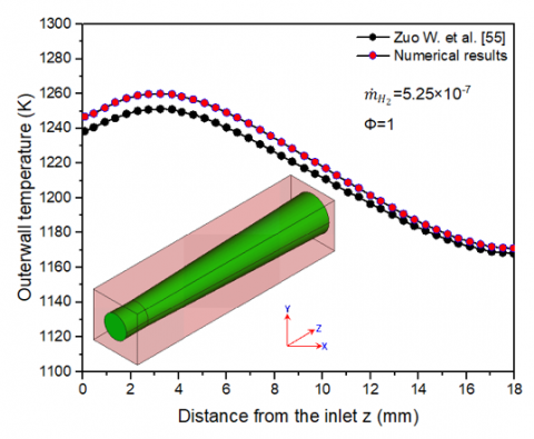
The fluctuating curves pattern of the external temperature of wall is generally adequate, as shown in Figure 4. The deviation among the current results and the obtained results numerically by Zuo et al. [35] is less than 2%. According to Akhtar et al. [33] the combustors of micro-tube with different CS exhibit similar shifting patterns, with the exception of the highest temperature of wall and its rate of variation. Consequently, the numerical model described above may be used to analyse and evaluate the thermal performance of improved circular, square, and flat MC.
Figure 4. Model verification
The most important parameter in systems of micro-power which use heat radiation flux to generate electricity is flam temperature. Flame temperature characterizes heat transfer properties and consequently system output, as well as providing insight into choosing optimal combustor material [44]. The CS of a MC is improved in order to produce excessive and uniform power production through the outer wall of combustor. These factors adjust the amount of chemical heat rate and the transfer heat released via combustion. Therefore, the MFR and heat combination transfer area are reserved persistent. An additional the wall of combustor thickness is considerable factor that influences the distribution of temperature at the MC walls, which has to be kept constant for correct comparison.
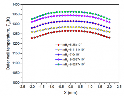
Five typical $\dot{m} H_2$ (MFRs) extended from 5.25×10⁻⁷ kg/s to 9.8245×10⁻⁷ kg/s were used to evaluate the influence of intake MFRs for different CSs at constant H2 ratio as equivalence of (Ф=1.0). For all tested $\dot{m} H_2$ MFRs, the distributions of outer temperature of wall along the axial (Z) direction is shown in Figure 5 (a), and Figure 5 (b) displays the outer temperature of wall distributions besides the CSal (X) direction of the circular MCs at (Z=3.0 mm). The results show that the temperature of the outside wall rises abruptly to a peak, and then drops at the measured position far away from the entrance to the minimum value.
The higher outer temperature of wall relegated to the $\dot{m} H_2$ MFRs of 9.8245×10⁻⁷ kg/s at constant H ratio as equivalence of (Ф=1.0). Furthermore, the greater is the $\dot{m} H_2$ -MFR, the greater temperature of the outer wall. As a result, elevating the flow rate leads to a greater and more uniform temperature of wall since extra fuel is consumed by time, resulting in a faster release of heat rate.
(a)
(b)
Figure 5. (a) Outer temperature of wall profile for different inlet $\dot{m} H_2$ MFR and at 1.0 ratio as equivalence for circular cross sectional MC, (b) The outer temperature of wall was compared with varying input $\dot{m} H_2$ MFRs and 1.0 ratio as equivalence for circular CS MC
Figures 6 (a) and (b) demonstrate the impact of geometry on distribution of the temperature of wall for 1.0 ratio as equivalence and inlet $\dot{m} H_2$ MFR at 5.25×10⁻⁷ kg/s. The results illustrate that the flat CS temperature of MC outer wall is more uniform and greater compared to circular and square cross section MCs on the X and Z directions. Additionally, Figure 6 shows the flat CS yields the maximum outer temperature of wall for ratio as equivalence values, area transfer heat, combustor thickness of wall, and MFR respectively. At 3.2 mm combustor downstream, the flat CS reaches a maximum temperature of roughly 1328 K. Moreover, the flat micro-mean combustor's outer temperature of wall in the (Z) direction is 1260.8 K, at a 1.0 ratio as equivalence and 5.25×10⁻⁷ kg/s $\dot{m} H_2$ MFR. On the other hand, square and Circular MCs have means outer temperature of walls around 1216.3 K and 1221.1 K respectively. This behaviour has also been documented in the literature [33, 38]. The MCs outer temperature of wall with varied CS has the similar shifting patterns as the highest temperature of wall and the development and decline outer wall rate of section for the same intake and other boundary circumstances, according to literature [33, 38].
(a)
(b)
Figure 6. (a) Outer temperature of wall profile for varied CS with $\dot{m} H_2$ 5.25×10⁻⁷ kg/s input MFR of and 1.0 equivalency ratio, (b) Outer temperature of walls comparison with varied cross section at Z=3 mm
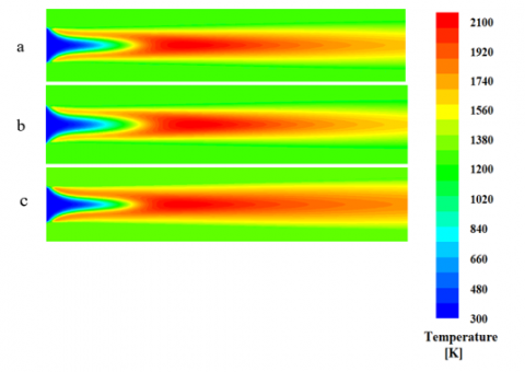
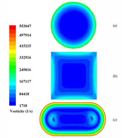
In this study it is assumed that Plane cuts across the MC. Figure 7 delineates temperature forms for non-circular and circular CSs. The maximum temperature is calculated at the outer flat CS wall for the identical values of $\dot{m} H_2$ MFR, ratio as equivalence, hydraulic diameter, and wall of combustor thickness. At 3.2 mm combustor downstream, the flat CS reaches a maximum temperature of roughly 1328 K. The temperature raises the least in the square CS, whereas it raises the most in the flat CS. As seen in Figure 8, the elevated outer temperature of wall for the flat CS might be ascribed to the gaseous mixture's vorticity being higher than for the other CSs. Consequently, the effective mass and heat movement, the temperature of walls is uniform and high.
Figure 7. Temperature contours at 3 mm downstream for (a) circular, (b) square, and (c) flat CS at 5.25×10⁻⁷ kg/s and 1.0 ratio as equivalence
Figure 8. Vorticity contours at 3 mm downstream for (a) circular, (b) square, and (c) flat CS, at 1.0 ratio as equivalence, and $\dot{m} H_2$ 5.25×10⁻⁷ kg/s
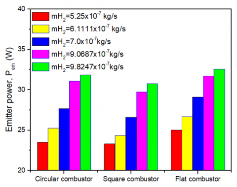
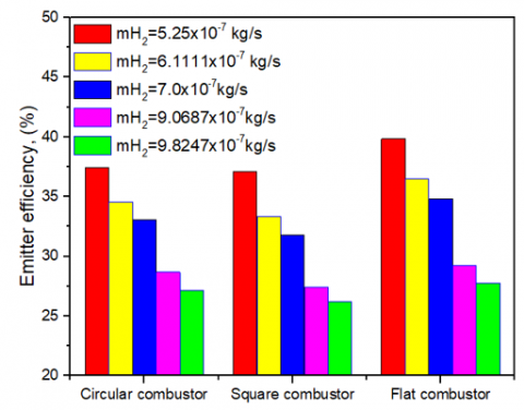
The impacts of the $\dot{m} H_2$ MFR on efficiency of emitter and power of emitter of different micro tube combustors such as circular, square, and flat are shown in Figure 9 (a) and (b) at 1.0 H/air equivalency ratio and flow rate at 5.25×10⁻⁷ kg/s to 9.8247×10⁻⁷ kg/s. When the $\dot{m} H_2$ MFR increases, the efficiency of emitter of micro-circular, square and flat tube combustors decrease as shown in Figure 9 (a). On the other hand, the emitter micro-circular efficiency of square and flat tube combustors decreases if the $\dot{m} H_2$ MFR increases as shown in Figure 9 (b). It can be concluded, the increasing of H2 flow rate causes additional chemical potential energy release through combustion chemical processes.
Consequently, as the $\dot{m} H_2$ MFR rises, the input velocity rises dramatically, resulting in incomplete combustion. Finally, the gas that has been burnt releases more energy. Nonetheless, at all $\dot{m} H_2$ MFRs, the power of emitter and efficiency of emitter of flat combustor are higher than circular and square combustor. This result can be attributed to the flat combustor's geometrical form and the mean outer temperature of wall.
(a)
(b)
Figure 9. (a) $\dot{m} H_2$ MFR effects on micro-circular, square, and flat tube combustors' power of emitter, (b) $\dot{m} H_2$ MFR effects on micro-circular, square, and flat tube combustors' efficiency of emitter
(a)
(b)
Figure 10. (a) Influences of the H equivalency ratio on micro-circular, square, and flat tube combustors’ power of emitter, (b) Effects of the H equivalency ratio on micro-circular, square, and flat tube combustors' efficiency of emitter
The H/air ratio as equivalence has a significant influence on the power of emitter and efficiency of emitter of the micro-circular, square, and flat combustors as shown in Figure 10 (a), and 10 (b). This impact is observable by reducing H/air ratio as equivalence from 1.0 to 0.8 and setting $\dot{m} H$ /air MFR at 5.25 10 kg/s. As shown, decreasing in H/air equivalency ratio has caused a reduction in power of emitter and efficiency of emitter. This reduction has been occurred because of decreasing heat transmission between the inside wall of combustor and the burnt gas as a result of the lower of H/air equivalency. In addition, the lower of H/air equivalency has allowed more thermal energy to be absorbed by the unburned gas. Figure 10 (a) and 10 (b) illustrate that the highest emitted power (25.1 W) and emitted efficiency ratio (39.8%) have been recorded of the MC with flat cross section, followed by the circular combustor with 23.5 W and 37.4% and the square combustor with 23.3 W and 37.1%. It might be arrived to a conclusion that the MC with a flat CS is most efficient than the other two CSs.
In this study, investigation being numerical of a pre-mixed H/air reacting flow inside MC with different CS such as circular, square, and flat was presented. In addition, various $\dot{m} H_2$ MFRs and premixed H/air equivalency ratios had been taken into consideration to assess the impact of cross sectional of MC. And then, the numerical outcomes had been explored and compared. The flat CS of modified combustor achieved the greatest thermal improvement and efficiency of emitter with $\dot{m} H_2$ MFR from 5.250×10⁻⁷ kg/s to 9.82450×10⁻⁷ kg/s. The increased vorticity caused by the combustor's CSal form and the improved vorticity providing effective heat transfer in the recirculation area can be ascribed to this. It might be arrived to a conclusion that if the advantage of the MC with a flat CS is completely leveraged, the conversion energy of the system of MTPV may be significantly increased.
[1] Maruta, K. (2011). Micro and mesoscale combustion. Proceedings of the Combustion Institute, 33(1): 125-150. https://doi.org/10.1016/j.proci.2010.09.005
[2] Chou, S.K., Yang, W.M., Chua, K.J., Li, J., Zhang, K.L. (2011). Development of micro power generators–A review. Applied Energy, 88(1): 1-16. https://doi.org/10.1016/j.apenergy.2010.07.010
[3] Epstein, A.H., Senturia, S.D. (1997). Macro power from micro machinery. Science, 276(5316): 1211-1211. https://doi.org/10.1126/science.276.5316.1211
[4] Jiaqiang, E., Zuo, W., Liu, H., Peng, Q. (2016). Field synergy analysis of the micro-cylindrical combustor with a step. Applied Thermal Engineering, 93: 83-89. https://doi.org/10.1016/j.applthermaleng.2015.09.028
[5] Zuo, W., Jiaqiang, E., Liu, X., Peng, Q., Deng, Y., Zhu, H. (2016). Orthogonal experimental design and fuzzy grey relational analysis for emitter efficiency of the micro-cylindrical combustor with a step. Applied Thermal Engineering, 103: 945-951. https://doi.org/10.1016/j.applthermaleng.2016.04.148
[6] Alipoor, A., Mazaheri, K. (2014). Studying the repetitive extinction-ignition dynamics for lean premixed hydrogen-air combustion in a heated microchannel. Energy, 73: 367-379. https://doi.org/10.1016/j.energy.2014.06.027
[7] Alipoor, A., Mazaheri, K. (2016). Combustion characteristics and flame bifurcation in repetitive extinction-ignition dynamics for premixed hydrogen-air combustion in a heated micro channel. Energy, 109: 650-663. https://doi.org/10.1016/j.energy.2016.05.042
[8] Ran, J., Li, L., Du, X., Wang, R., Pan, W., Tang, W. (2015). Numerical investigations on characteristics of methane catalytic combustion in micro-channels with a concave or convex wall cavity. Energy Conversion and Management, 97: 188-195. https://doi.org/10.1016/j.enconman.2015.03.058
[9] Jiaqiang, E., Cai, L., Li, J., Ding, J., Chen, J., Luo, B. (2022). Effects analysis on the catalytic combustion and heat transfer performance enhancement of a non-premixed hydrogen/air micro combustor. Fuel, 309: 122125. https://doi.org/10.1016/j.fuel.2021.122125
[10] Pan, J.F., Wu, D., Liu, Y.X., Zhang, H.F., Tang, A.K., Xue, H. (2015). Hydrogen/oxygen premixed combustion characteristics in micro porous media combustor. Applied Energy, 160: 802-807. https://doi.org/10.1016/j.apenergy.2014.12.049
[11] Wu, Y., Peng, Q., Yang, M., Shan, J., Yang, W. (2021). Entropy generation analysis of premixed hydrogen–air combustion in a micro combustor with porous medium. Chemical Engineering and Processing-Process Intensification, 168: 108566. https://doi.org/10.1016/j.cep.2021.108566
[12] Fan, A., Zhang, H., Wan, J. (2017). Numerical investigation on flame blow-off limit of a novel microscale Swiss-roll combustor with a bluff-body. Energy, 123: 252-259. https://doi.org/10.1016/j.energy.2017.02.003
[13] Li, L., Fan, A. (2021). A numerical study on non-premixed H2/air flame stability in a micro-combustor with a slotted bluff-body. International Journal of Hydrogen Energy, 46(2): 2658-2666. https://doi.org/10.1016/j.ijhydene.2020.10.024
[14] Xu, F., Yan, Y., He, Z., Yang, Z., Zhang, L. (2021). Numerical study on the influence of controllable flow ratio on combustion characteristics of a controllable central slotted bluff body and cavity combined micro combustor. International Journal of Hydrogen Energy, 46(9): 6901-6914. https://doi.org/10.1016/j.ijhydene.2020.11.117
[15] Zhao, D., Ji, C., Li, X., Li, S. (2015). Mitigation of premixed flame-sustained thermoacoustic oscillations using an electrical heater. International Journal of Heat and Mass Transfer, 86: 309-318. https://doi.org/10.1016/j.ijheatmasstransfer.2015.03.012
[16] Gan, Y., Tong, Y., Ju, Y., Zhang, X., Li, H., Chen, X. (2017). Experimental study on electro-spraying and combustion characteristics in meso-scale combustors. Energy Conversion and Management, 131: 10-17. https://doi.org/10.1016/j.enconman.2016.11.015
[17] Wan, J., Fan, A., Yao, H., Liu, W. (2016). Experimental investigation and numerical analysis on the blow-off limits of premixed CH4/air flames in a mesoscale bluff-body combustor. Energy, 113: 193-203. https://doi.org/10.1016/j.energy.2016.07.047
[18] Wan, J., Zhao, H. (2017). Dynamics of premixed CH4/air flames in a micro combustor with a plate flame holder and preheating channels. Energy, 139: 366-379. https://doi.org/10.1016/j.energy.2017.08.002
[19] Vijayan, V., Gupta, A.K. (2010). Combustion and heat transfer at meso-scale with thermal recuperation. Applied Energy, 87(8): 2628-2639. https://doi.org/10.1016/j.apenergy.2010.03.011
[20] Gan, Y., Chen, X., Tong, Y., Zhang, X., Zhang, Y. (2018). Thermal performance of a meso-scale combustor with electrospray technique using liquid ethanol as fuel. Applied Thermal Engineering, 128: 274-281. https://doi.org/10.1016/j.applthermaleng.2017.09.016
[21] Cam, O., Yilmaz, H., Tangoz, S., Yilmaz, I. (2017). A numerical study on combustion and emission characteristics of premixed hydrogen air flames. International Journal of Hydrogen Energy, 42(40): 25801-25811. https://doi.org/10.1016/j.ijhydene.2017.07.017
[22] Yilmaz, H., Cam, O., Yilmaz, I. (2017). Effect of micro combustor geometry on combustion and emission behavior of premixed hydrogen/air flames. Energy, 135: 585-597. https://doi.org/10.1016/j.energy.2017.06.169
[23] Yang, W.M., Chou, S.K., Shu, C., Li, Z.W., Xue, H. (2002). Combustion in micro-cylindrical combustors with and without a backward facing step. Applied Thermal Engineering, 22(16): 1777-1787. https://doi.org/10.1016/S1359-4311(02)00113-8
[24] Yang, W.M., Chou, S.K., Shu, C., Li, Z.W., Xue, H. (2002). Development of microthermophotovoltaic system. Applied Physics Letters, 81(27): 5255-5257. https://doi.org/10.1063/1.1533847
[25] Wierzbicki, T.A., Lee, I.C., Gupta, A.K. (2014). Combustion of propane with Pt and Rh catalysts in a meso-scale heat recirculating combustor. Applied Energy, 130: 350-356. https://doi.org/10.1016/j.apenergy.2014.05.069
[26] Ma, L., Fang, Q., Zhang, C., Chen, G. (2021). A novel Swiss-roll micro-combustor with double combustion chambers: A numerical investigation on effect of solid material on premixed CH4/air flame blow-off limit. International Journal of Hydrogen Energy, 46(29): 16116-16126. https://doi.org/10.1016/j.ijhydene.2021.02.118
[27] Tang, A., Cai, T., Deng, J., Xu, Y., Pan, J. (2017). Experimental investigation on combustion characteristics of premixed propane/air in a micro-planar heat recirculation combustor. Energy Conversion and Management, 152: 65-71. https://doi.org/10.1016/j.enconman.2017.09.011
[28] Kim, T.Y., Kim, H.K., Ku, J.W., Kwon, O.C. (2017). A heat-recirculating combustor with multiple injectors for thermophotovoltaic power conversion. Applied Energy, 193: 174-181. https://doi.org/10.1016/j.apenergy.2017.02.040
[29] Jiang, D., Yang, W., Tang, A. (2015). Development of a high-temperature and high-uniformity micro planar combustor for thermophotovoltaics application. Energy Conversion and Management, 103: 359-365. https://doi.org/10.1016/j.enconman.2015.06.083
[30] He, Z., Yan, Y., Zhao, T., Feng, S., Li, X., Zhang, L., Zhang, Z. (2021). Heat transfer enhancement and exergy efficiency improvement of a micro combustor with internal spiral fins for thermophotovoltaic systems. Applied Thermal Engineering, 189: 116723. https://doi.org/10.1016/j.applthermaleng.2021.116723
[31] Ansari, M., Amani, E. (2018). Micro-combustor performance enhancement using a novel combined baffle-bluff configuration. Chemical Engineering Science, 175: 243-256. https://doi.org/10.1016/j.ces.2017.10.001
[32] Zuo, W., Jiaqiang, E., Liu, H., Peng, Q., Zhao, X., Zhang, Z. (2016). Numerical investigations on an improved micro-cylindrical combustor with rectangular rib for enhancing heat transfer. Applied Energy, 184: 77-87. https://doi.org/10.1016/j.apenergy.2016.10.009
[33] Akhtar, S., Kurnia, J.C., Shamim, T. (2015). A three-dimensional computational model of H2–air premixed combustion in non-circular micro-channels for a thermo-photovoltaic (TPV) application. Applied Energy, 152: 47-57. https://doi.org/10.1016/j.apenergy.2015.04.068
[34] Zuo, W., Jiaqiang, E., Hu, W., Jin, Y., Han, D. (2017). Numerical investigations on combustion characteristics of H2/air premixed combustion in a micro elliptical tube combustor. Energy, 126: 1-12. https://doi.org/10.1016/j.energy.2017.03.011
[35] Zuo, W., Jiaqiang, E., Lin, R. (2018). Numerical investigations on an improved counterflow double-channel micro combustor fueled with hydrogen for enhancing thermal performance. Energy Conversion and Management, 159: 163-174. https://doi.org/10.1016/j.enconman.2018.01.017
[36] Kuo, C.H., Ronney, P.D. (2007). Numerical modeling of non-adiabatic heat-recirculating combustors. Proceedings of the Combustion Institute, 31(2): 3277-3284. https://doi.org/10.1016/j.proci.2006.08.082
[37] Li, J., Chou, S.K., Yang, W.M., Li, Z.W. (2008). Experimental and numerical study of the wall temperature of cylindrical micro combustors. Journal of Micromechanics and Microengineering, 19(1): 015019. https://doi.org/10.1088/0960-1317/19/1/015019
[38] Yang, W.M., Chua, K.J., Pan, J.F., Jiang, D.Y., An, H. (2014). Development of micro-thermophotovoltaic power generator with heat recuperation. Energy conversion and management, 78: 81-87. https://doi.org/10.1016/j.enconman.2013.10.040
[39] Giovangigli, V., Smooke, M.D. (1987). Extinction of strained premixed laminar flames with complex chemistry. Combustion Science and Technology, 53(1): 23-49. https://doi.org/10.1080/00102208708947017
[40] Oran, E.S., Boris, J.P., Boris, J.P. (2001). Numerical simulation of reactive flow. Cambridge: Cambridge University Press.
[41] Di Benedetto, A., Di Sarli, V., Russo, G. (2009). A novel catalytic-homogenous micro-combustor. Catalysis Today, 147: S156-S161. https://doi.org/10.1016/j.cattod.2009.07.030
[42] Norton, D.G., Vlachos, D.G. (2004). A CFD study of propane/air microflame stability. Combustion and Flame, 138(1-2): 97-107. https://doi.org/10.1016/j.combustflame.2004.04.004
[43] Tang, A., Xu, Y., Pan, J., Yang, W., Jiang, D., Lu, Q. (2015). Combustion characteristics and performance evaluation of premixed methane/air with hydrogen addition in a micro-planar combustor. Chemical Engineering Science, 131: 235-242. https://doi.org/10.1016/j.ces.2015.03.030
[44] Li, J., Chou, S.K., Yang, W.M., Li, Z.W. (2009). A numerical study on premixed micro-combustion of CH4–air mixture: Effects of combustor size, geometry and boundary conditions on flame temperature. Chemical Engineering Journal, 150(1): 213-222. https://doi.org/10.1016/j.cej.2009.02.015