Nasir Ahmed Alawad* | Amjad J. Humaidi | Ahmed Sabah Al-Araji
© 2022 IIETA. This article is published by IIETA and is licensed under the CC BY 4.0 license (http://creativecommons.org/licenses/by/4.0/).
OPEN ACCESS
This work focuses on design of trajectory-tracking control based on active disturbance rejection control (ADRC) controller for knee joint exoskeleton device. The device is worn by disable patients and it is actuated by ADRC to perform the exercises prescribed by physician doctor for rehabilitation of humanoid's lower limb. In order to improve the tracking performance and robustness characteristics of ADRC, minor modification has been made in its structure, which is represented by adding feed forward control signal to reference angular acceleration. The numerical simulations via MATLAB software environment have been conducted with various model uncertainties and external disturbances to assess the performance of modified control scheme. The proposed controller showed improvement in trajectory tracking error, rejection of exerted disturbances, and robustness against parameter uncertainties.
exoskeleton system, ADRC controller, PID controller, tracking performance, robustness
Physically disabled people can take care of themselves in everyday life with the help of an exoskeleton robot. For humans to accomplish daily activities, the lower-limb motions knee is extremely crucial. Up to now, exoskeletons for knee mobility assistance have been proposed for daily use or rehabilitation. Several exoskeleton leg systems have been investigated and built since the 1950s [1, 2]. Sitting is one of the most significant everyday activities that involves knee mobility. In terms of segmental lengths and center of rotation placement, the exoskeleton robot should be adaptive to the human lower limb. Because the exoskeleton robot is intended to be used for everyday tasks, it should be able to generate flexible and smooth motions. When compared to other bodily joints, the knee joint has the most constraints, with strong muscles and ligaments limiting various actions that can harm the knee. The connection between the exoskeleton and the human's leg should be as suitable as possible, with no abrupt movements that could cause discomfort and instability to the user in the interaction zones [3]. As a result, the position controller should avoid trajectory oscillations and overshoot responses. This behavior can be achieved by adjusting a controller properly.
The proportional–integral–derivative (PID) controller can be used to manage the required outcome of the exoskeleton; however, despite its ease of development, the convergence analysis and coefficients adjustment limit its application, and it also suffers when the system is disturbed [4]. Soft computing algorithms, like as fuzzy sets and neural networks (NNs), have been investigated for many years. For the exoskeleton, a fuzzy controller with a bang-bang controller was developed, and a Radial Basis Functions (RBF) neural network was applied to correct for the disturbance, but both of these algorithms require a lot of processing power [5, 6].
Sliding mode control (SMC) may be a useful method because to its adaptability to existing system uncertainty as well as external disturbances, but it suffers from chattering due to discontinuity switching, which can result in sensor damage [7, 8]. In such situations, robust control methods are one solution, but these methods are restrictive and reflect terrible scenarios at the expense of transient response. As a result, such controllers are unable to react quickly enough in the situation of significant disturbances. (ADRC) was created by Gao et al. [9] to overcome these restrictions and offered several advantages. With evident advantages in performance and practicality, ADRC was capable of substituting PID strategy and proposing answers for problems under disturbances [10]. The increasing adoption of ADRC in industry during the last three decades demonstrates its utility in a variety of applications [11-13]. The fundamental premise of ADRC is the capability to predict "total disturbance" induced by unknown simulation model and external disturbances on-line.
ADRC is used for various robotic rehabilitation devices for tracking applications in the lower limb rehabilitation category. According to Long et al. [14], clinical gait data was employed as a reference and a linear extended state observer (LESO) based ADRC was applied to the lower limb exoskeleton for knee joints. When the results of PID and ADRC are compared for the knee trajectories, the results demonstrate that ADRC outperforms PID by a small margin. To increase tracking performance, a suggested (ADRC) with fast terminal sliding mode control (FTSMC) can not only reduce disturbance but also quickly converge to a limited region, however there is significant chattering [15]. The feedback design, on the other hand, is based on the existence of a Control Lyapunov Function (CLF) and the Sontag's formula rather than a PD controller used with an Extended State Observer (ESO) to design and estimate unknown disturbances on-line and canceled by introducing the ESO output into the feedback loop. Where ARDC's usefulness is demonstrated through experimentation and adaptation. There are numerous rehabilitation control schemes [16], however position tracking is one of the most basic control strategies for robotic rehabilitation devices, in which the controller improves the repeatability and position precision of motion for the patient's recovery [17, 18].
Since the exoskeleton knee system is designed to be utilized in everyday tasks, it should be able to provide versatile and smooth motions. As shown in Figure 1-a, one right leg contains a thigh holder, a lower leg holder, a DC motor, and two (position, current) sensors. The knee device is worn by users to assist the motion of their lower-limb in sitting situation. Knee joints have only one active DOF (flexion/extension). The desired control signal generated by ADRC is fed to DC motor to develop the required torque for prescribed motion. The range of angular movement in human knee is usually limited between 135° of flexion and 0° of extension, with 90° being the rest position. For safety, the stopper is attached for motion to prevent the movable range from being exceeded. Furthermore, for reliability, the maximum torque of actuating motor is regulated by equipment and software. Mechanical constraints were designed to allow the human body model and the exoskeleton model to interact freely in a practical condition. The mechanism of actuating the leg at joint level for rehabilitation exercises is shown in Figure 1-b [19].
Figure 1. (a) Knee exoskeleton prototype; (b) Mechanism of actuating knee motion [20]
The exoskeleton and human model were modeled as a system of rigid bodies with one degree of freedom for knee part. The nonlinear dynamic for the exoskeleton and human model with one joint, at the knee, is determined through the use of the Euler–Lagrange method. The dynamic modeling of the system can be expressed as follows [21-23]:
$J \ddot{\theta}=-\tau_{g} \cos \theta-f_{s} s g n \dot{\theta}-f_{v} \dot{\theta}+\tau_{h}+\tau$
where, $\theta$ is the knee joint angle between the actual position of the shank and the full extension position, $\dot{\theta}$ and $\ddot{\theta}$ are, respectively, the knee joint angular velocity and acceleration. $J, f_{s}, f_{v}, \tau_{g}$, and $\tau$ are the leg inertia, solid friction coefficient, viscous friction coefficient, gravity torque, and the actuating torque, which is applied to the Knee-Exoskeleton system at the knee level, respectively. Letting $x_{1}$ and $x_{2}$ represent the variables $\theta$ and $\dot{\theta}$, the above equation can be written in state variable:
$\dot{x}_{1}=x_{2}$
$\dot{x}_{2}=f+b_{o} \tau$ (1)
where, $b_{o}=1 / J$ and $f$ represents the lumped term of uncertainties and nonlinearities, which is given by:
$\frac{1}{J}\left[\tau_{g} \cos \left(x_{1}\right)-f_{v} x_{2}-f_{s} \operatorname{sign}\left(x_{2}\right)+\tau_{h}\right]$
As illustrated in Figure 2, the LADRC is composed of three main parts: a tracking differentiator (TD), an extended state observer (ESO), and a state error feedback control law (SEF), where the TD constructs the organized transition process and extracts the differential of each order of the input signal. In some situations, the transition process is extremely useful and even required. The core of ADRC is the ESO, which is used to estimate the total lumped uncertainties and disturbances.
Figure 2. Block Diagram of the ADRC control strategy
The following state space form can be used to express the standard system of Eq. (1) [24-26]:
$\dot{x}_{1}=x_{2}$
$\dot{x}_{2}=x_{3}+b_{o} \tau$
$\dot{x}_{3}=\dot{f}$
$y=x_{1}$ (2)
where, f represents the total disturbance and model uncertainties.
The proposed structure of observer dynamics for the system described by Eq. (2) is given by:
$\dot{\hat{\boldsymbol{z}}}=\boldsymbol{A} \hat{z}+\boldsymbol{B} \tau+\boldsymbol{\beta}(y-\hat{y})$
$\hat{y}=\boldsymbol{C} \hat{\boldsymbol{z}}$ (3)
where, $\hat{\boldsymbol{Z}}=\left[\begin{array}{lll}\hat{Z}_{1} & \hat{Z}_{2} & \hat{Z}_{3}\end{array}\right]^{T}$ is the vectors of estimates of $y, \dot{y}$ , and f, respectively. The observer described above is known as the LESO and $\boldsymbol{\beta}$ is termed as observer gain matrix. The elements of observer gain matrix $\boldsymbol{\beta}$ can be obtained using the pole-placement method. When properly designed and implemented, the estimated states of observer will track that of the plant defined by Eq. (2).
Based on pole-placement control technique, one can establish the following characteristic equation based on structure of extended state observer:
$Q(s)=|s \boldsymbol{I}-(\boldsymbol{A}-\boldsymbol{\beta} \boldsymbol{C})|=\left(s+\omega_{o}\right)^{3}$ (4)
The observe gain matrix can be evaluated as follows:
$\boldsymbol{\beta}=\left[\begin{array}{lll}3 \omega_{o} & 3 \omega_{o}^{2} & \omega_{o}^{3}\end{array}\right]$ (5)
In order to determine the elements of observer gain matrix, the bandwidth $\omega_{o}$ of LESO is only required. However, this simple tuning technique combines the trade-off between performance and noise-sensitivity. However, other modern and efficient optimization techniques can be consulted for tuning purposes of these parameters [27-32].
The task of TD is to perform time-derivative of the desired input and to provide both the original and derivative versions of reference input $y_{d}$. Both signals are fed to PD controller, which works according to the following expression:
$v_{o}=K_{p}\left(y_{d}-\hat{z}_{1}\right)+K_{d}\left(\dot{y}_{d}-\hat{z}_{2}\right)$ (6)
where, $K_{p}$ and $K_{d}$ are proportional and derivative gains, respectively. The performance of ADRC can be improved with an addition reference angular acceleration in feed forward path so that Eq. (6) can be rewritten as:
$v_{o}=K_{p}\left(y_{d}-\hat{z}_{1}\right)+K_{d}\left(\dot{y}_{d}-\hat{z}_{2}\right)+\ddot{y}_{d}$ (7)
The disturbance, represented by $x_{3}$, is estimated by $\hat{Z}_{3}$ and compensated by the following control law:
$v=v_{o}-\hat{z}_{3} / b_{o}$ (8)
It is worthy to notify that the actuated torque $\tau$ to the exoskeleton system is equivalent to the control law described by above equation.
Theorem: If the ESO is well-performed, the improved structure of ADRC used for controlling the system described by Eq. (1) can lead to $y \rightarrow y_{d}$ as $t \rightarrow \infty$.
Proof: If the ESO has been properly designed, and if $y_{d}$ is firstly and secondly differentiable, then $\hat{z}_{1} \rightarrow y_{d}$ and $\hat{z}_{2} \rightarrow \dot{y}_{d}$ as $t \rightarrow \infty$ . According to Eq. (7), the value of $v_{o} \rightarrow \ddot{y}_{d} \rightarrow \ddot{y}$ as $t \rightarrow \infty$. This leads to $y=y_{d}$.
Pursuing the analysis in Ref. [33] and recalling form the control theory that the bandwidth of the system has the following expression:
$\omega_{c}=10 / T_{s}$ (9)
where, Ts is the settling time of the system. In this study, the open-loop system has a settling time of Ts=0.408 sec. The bandwidth will be determined according to above equation to be 2.45 Hz.
Therefore, the bandwidth of the system can be calculated as $\omega_{c}=24.5$. If one chooses the bandwidth of observer $\omega_{o}$ to be equal to $\omega_{o}=4 \omega_{c}$, then it easy to calculate the elements of observer matrix gains $\left(\beta_{1}, \beta_{2}, \beta_{3}\right)$ according to Eq. (5) and the values of controller gains are given by $k_{p}=\omega_{c}^{2}, k_{d}=2 \omega_{c}$.
This study considered a healthy man who is 33 years old, weighs 75 kilograms, and stands 1.73 meters tall. The tested system, shown in Figure 1, comprises of a person in a sitting position wearing a lower limb exoskeleton, and selected parameters for this scenario based on Table 1 [21].
The computer simulations have been conducted via Matlab/Simulink environment to verify the effectiveness of proposed control approach for rehabilitation system. Two types of reference trajectory were presented to test the performance of modified ADRC. The first reference signal is represented by [5];
$y_{d 1}=60 \sin (0.5 \pi t)$
Table 1. Lists the numeric values of system parameters
|
Parameter |
Value |
|
Inertia ( J ) |
0.348 $k q \cdot m^{2}$ |
|
Solid Friction Coefficient ( $f_{s}$) |
0.998 $N \cdot m$ |
|
Viscous Friction Coefficient ($f_{v}$) |
0.872 N.m.s./rad |
|
Gravity Torque ($\tau_{g}$) |
3.445 N. $m$ |
The other reference profile is inspired from real motion of rehabilitation exercises for knee [34, 35]
$\begin{aligned} y_{d 2}=0.766 \cos &(0 . \pi t)-0.099 \cos (\pi t) \\ &-0.342 \sin (\pi t) \\ &-0.219 \cos (2 \pi t) \\ &+0.168 \sin (2 \pi t) \\ &+0.008 \cos (3 \pi t) \\ &+0.084 \sin (3 \pi t)-26.127 \end{aligned}$
Figure 3 shows the profile of reference trajectory $y_{d 2}$ for the knee joint.
Figure 3. The profile of real trajectory $y_{d 2}$
Two cases have been addressed in the numerical simulation. Case I discussed the control performance without disturbance, while Case II has accounted for the disturbance effect. Two types of disturbances have been given; one is a random disturbance and the other has stationary behavior.
4.1 Case I: Tracking performance without disturbance
The exoskeleton device can be adjusted to aid the human knee to recover its natural activities. The rehabilitation exercises are either using expert physician or utilizing exoskeleton system, which is fed by desired or prescribed reference motion. In this scenario, two types of desired trajectories can be applied as reference signal for the controlled system. These trajectories are described by $y_{d 1}$ and $y_{d 2}$.
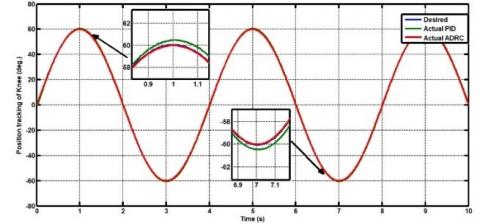
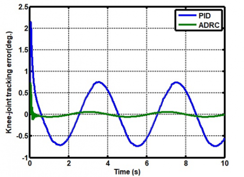
Figure 4 shows the performance of modified ADRC (MADRC) as compared to the PID controller without external disturbance and subjected to reference input $y_{d 1}$. The setting of classical PID controller's terms are found based on try-and-error procedure and they are $k_{p}=150, k_{d}=15, k_{i}=80$. Figure 5 show the trajectory tracking errors for both MADRC and PID controller. The Root Mean Square of Error (RMSE) is used as index for evaluation of tracking performance between the PID control and MLADRC. Based on Figure 5, the RMSE has been calculated to be (0.00588) and (0.5565) for MADRC and PID controller, respectively. This indicates that the MADRC is better than PID control in terms of accuracy.
Figure 4. Tracking performance based on PID controller and MADRC without disturbance
Figure 5. Track error of MADRC and PID controller
Figure 6. Transient responses of joint angle subjected to reference $y_{d 2}$
Figure 7. Tracking error based on MADRC and PID controller subjected to reference $y_{d 2}$
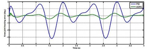
In the next simulation, the signal represented $y_{d 2}$ is applied to controlled system based on both proposed controllers. Figure 6 shows the tracking performances of MADRC and PID control. The transient responses of errors based on these controllers are shown in Figure 7. According to measures of RMSE, one can conclude that the MADRC outperforms the PID controller, where MADRC gives 0.1438 and the PID controller has 1.08 in terms of index RMSE.
4.2 Case II: Tracking performance with disturbance
In the next scenarios, two types of disturbances are exerted: stationary and random-type disturbance. These disturbances are added to torque control signal $v_{o}$ and represent gravity disturbance torque. However, the scenarios have been simulated when the controlled system commanded only by actual-like reference trajectory $y_{d 2}$.
The first simulation is implemented by exerting constant disturbance of amplitude $100 N . m$ at time $t=2 \mathrm{sec}$. The responses of knee angular positions based on PID control and MADRC are shown in Figure 8. Figure 9 demonstrates the behaviors of error dynamic resulting from both controllers. Based on REMSE measure, it is clear that the MADRC has better tracking accuracy than the PID controller, where the MADRC has recorded 0.3007 and the PID controller gives 1.953.
In the next scenario, the performance of MADRC is compared with the PID controller when the controlled system is encountered a random disturbance within bounds (-10, 10) $\mathrm{N} \cdot \mathrm{m}$. The responses of knee angular angles due to PID controller and MADRC as shown in Figure 10. The behaviors of tracking error are illustrated in Figure 11. It has been shown that the RMSE for PID controller is equal to (1.076), while the RMSE value for MADRC is equal (0.144). Based on these records, the accuracy resulting from MADRC is better than that resulting from PID controller.
Figure 8. Tracking performance based on PID controller and MADRC subjected to constant disturbance
Figure 9. Behaviors of error due to MADRC and PID controller with constant disturbance
Figure 10. Transient responses of joint angle subjected to random disturbance
Figure 11. show tracking errors of MADRC and PID controller with random disturbance
4.3 Performance Study of ESO
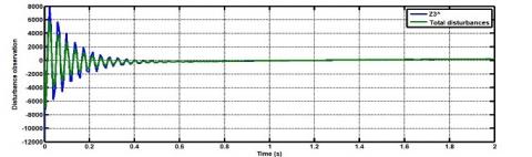
The main part in the structure of MADRC is the ESO. Better performance of ESO leads to improved performance of MADRC. Therefore, this simulation part is devoted to study the performance of ESO in the presence of disturbance. The main interesting state in ESO is the $\hat{z}_{3}$, which is responsible for estimating the total disturbance, represented by $f(t)$ in extended dynamic system of Eq. (2).
Figure 12. The behavior of state estimate $\hat{z}_{3}$ for $f$with free-disturbance ( $\tau_{h}=0$ ) and the reference is $y_{d 1}$
Figure 13. The behavior of state estimate $\hat{z}_{3}$ for $f$ with disturbance ( $\tau_{h}=10 \mathrm{~N} . \mathrm{m}$) and the reference is $y_{d 1}$
Figure 14. The behavior of state estimate $\hat{z}_{3}$ for $f$with disturbance ( $\tau_{h}=0$ ) and the reference is $y_{d 2}$
In addition, this part focuses on the robustness characteristics of observer to estimate the total disturbance subjected to different load conditions $\left(\tau_{h}\right)$ with two types of commanded references. In Figure 12 , the estimated state $\hat{z}_{3}$ is demonstrated when the system is free from any disturbance $\left(\tau_{h}=0\right)$ and the controlled system is commanded with sinusoidal reference $y_{d 1}$. In this case, the estimated state $\hat{z}_{3}$ will estimate all nonlinearity and uncertainty function $f$ as indicated in Eq. (1), but with the term associated with $\tau_{h}$ is set to zero. Figure 13 shows the behavior of state estimate $\hat{z}_{3}$ when a constant disturbance $\left(\tau_{h}=10 \mathrm{~N} . \mathrm{m}\right)$ is applied to the controlled system at time 2 sec based on reference $y_{d 1}$. It is clear from the figure that the ESO could successfully track the applied load together with all terms of uncertainty function $f$ in such a way the MADRC could compensate this load change. Figure 14 repeats the scenario of Figure 12 , but with presence of reference trajectory $y_{d 2}$. Again, the state $\hat{z}_{3}$ of ESO could estimate the applied change $f(t)$ very closely.
Figure 15. The behavior of state estimate $\hat{z}_{3}$ for $f$ with random disturbance $\tau_{h}=[-10,10]$ and reference $y_{d 2}$
In Figure 15 , a random disturbance $\tau_{h}$ with bounds ( $-10$ to 10) N.m has been exerted at $2 \mathrm{sec}$ when the controlled system is commanded with reference trajectory $y_{d 2}$. It is evident form the figure that the estimate state $\hat{z}_{3}$ tracks $f(t)$ very closely.
This study presented the design of modified ADRC for motion control of joint angle for exoskeleton knee-device. The performance of modified ADRC has been assessed via numerical simulation and compared to conventional PID controller in terms of transient and robust characteristics. The computer simulations have been conducted for two types of commanded signals and the simulated results showed that the MADRC could give better robustness and transient features than the PID controller. In addition, the effectiveness of ESO, which is the core part of ADRC, has been studied and evaluated via computer simulation for specified load exertion. The simulated results showed that the ESO could successfully estimate the uncertainties irrespective the type of commanded reference trajectories. This study can be extended for future work either by including recent observation techniques or to design other control schemes either for enhancing the ADRC or for the purpose of comparison in performance [36-40].
The author would like to thank the Control and Systems Engineering Department for its support in the present work.
|
J |
Exoskeleton Inertia (Kg.m2) |
|
τg |
Gravity Torque (N.m) |
|
fs |
Solid Friction (N.m) |
|
fv |
Viscous Friction (N.m.sec./rad) |
|
θ |
Knee joint angle (rad) |
|
τ |
Applied Torque (N.m) |
|
ωc |
Controller Bandwidth (rad/sec) |
|
ωo |
Observer Bandwidth (rad/sec) |
|
PID |
Proportional integral derivative |
|
DOF |
Degree of Freedom |
|
ESO |
Extended state observer |
|
SEF |
State error feedback |
|
TD |
Tracking differentiator |
|
RMSE |
Root-Mean-Square of Error |
|
MADRC |
Modified Active Disturbance Rejection Control |
[1] Chen, B., Ma, H., Qin, L. Y., Gao, F., Chan, K. M., Law, S.W., Qin, L., Liao, W.H. (2016). Recent developments and challenges of lower extremity exoskeletons. Journal of Orthopaedic Translation, 5: 26-37. https://doi.org/10.1016/j.jot.2015.09.007
[2] Fox, S., Aranko, O., Heilala, J., Vahala, P. (2019). Exoskeletons: Comprehensive, comparative and critical analyses of their potential to improve manufacturing performance. Journal of Manufacturing Technology Management, 31(6): 1261-1280. https://doi.org/10.1108/JMTM-01-2019-0023
[3] Moreno, J.C. (2021). Wearable robotics: Challenges and trends. Proceedings of the 5th International Symposium on Wearable Robotics, WeRob2020, Pisa, Italy. https://doi.org/10.1007/978-3-030-01887-0
[4] Humaidi, A.J., Abdulkareem, A.I. (2019). Design of augmented nonlinear PD controller of Delta/Par4-like robot. Journal of Control Science and Engineering. https://doi.org/10.1155/2019/7689673
[5] Zhao, W., Song, A. (2020). Active motion control of a knee exoskeleton driven by antagonistic pneumatic muscle actuators. Multidisciplinary Digital Publishing Institute, 9(4): 1-14. https://doi.org/10.3390/act9040134
[6] Yang, Z., Zhu, Y., Yang, X., Zhang, Y. (2009). Impedance control of exoskeleton suit based on adaptive RBF neural network. In 2009 International conference on Intelligent Human-Machine Systems and Cybernetics, 1: 182-187. https://doi.org/10.1109/IHMSC.2009.54
[7] Humaidi, A.J., Tala'at, E.N., Hameed, M.R., Hameed, A.H. (2019). Design of adaptive observer-based backstepping control of cart-pole pendulum system. In 2019 IEEE International Conference on Electrical, Computer and Communication Technologies (ICECCT), pp. 1-5. https://doi.org/10.1109/ICECCT.2019.8869179
[8] Cao, J., Xie, S.Q., Das, R. (2017). MIMO sliding mode controller for gait exoskeleton driven by pneumatic muscles. IEEE Transactions on Control Systems Technology, 26(1): 274-281. https://doi.org/10.1109/TCST.2017.2654424
[9] Gao, Z., Huang, Y., Han, J. (2001). An alternative paradigm for control system design. In Proceedings of the 40th IEEE Conference on Decision and Control (Cat. No. 01CH37228), 5: 4578-4585. https://doi.org/10.1109/CDC.2001.980926
[10] Han, J. (2009). From PID to active disturbance rejection control. IEEE Transactions on Industrial Electronics, 56(3): 900-906. https://doi.org/10.1109/TIE.2008.2011621
[11] Gao, Z., Hu, S., Jiang, F. (2001). A novel motion control design approach based on active disturbance rejection. In Proceedings of the 40th IEEE Conference on Decision and Control (Cat. No. 01Ch37228), 5: 4877-4882. https://doi.org/10.1109/CDC.2001.980980
[12] Zhu, E., Pang, J., Sun, N., Gao, H., Sun, Q., Chen, Z. (2014). Airship horizontal trajectory tracking control based on active disturbance rejection control (ADRC). Nonlinear Dynamics, 75(4): 725-734. https://doi.org/10.1007/s11071-013-1099-x
[13] Humaidi, A.J., Oglah, A.A., Abbas, S.J., Ibraheem, I.K. (2019). Optimal augmented linear and nonlinear PD control design for parallel robot based on PSO tuner. International Review on Modelling and Simulations, 12(5): 281-291. https://doi.org/10.15866/iremos.v12i5.16298
[14] Long, Y., Du, Z., Cong, L., Wang, W., Zhang, Z., Dong, W. (2017). Active disturbance rejection control based human gait tracking for lower extremity rehabilitation exoskeleton. ISA Transactions, 67: 389-397. https://doi.org/10.1016/j.isatra.2017.01.006
[15] Chen, C.F., Du, Z.J., He, L., Wang, J.Q., Wu, D.M., Dong, W. (2019). Active disturbance rejection with fast terminal sliding mode control for a lower limb exoskeleton in swing phase. IEEE Access, 7: 72343-72357. https://doi.org/10.1109/ACCESS.2019.2918721
[16] Meng, W., Liu, Q., Zhou, Z., Ai, Q., Sheng, B., Xie, S.S. (2015). Recent development of mechanisms and control strategies for robot-assisted lower limb rehabilitation. Mechatronics, 31: 132-145. https://doi.org/10.1016/j.mechatronics.2015.04.005
[17] Long, Y., Du, Z. J., Wang, W.D., Dong, W. (2016). Robust sliding mode control based on GA optimization and CMAC compensation for lower limb exoskeleton. Applied Bionics and Biomechanics. https://doi.org/10.1155/2016/5017381
[18] Yunardi, R.T., Firdaus, A.A., Agustin, E.I. (2017). Robotic leg design to analysis the human leg swing from motion capture. Bulletin of Electrical Engineering and Informatics, 6(3): 256-264. https://doi.org/10.11591/eei.v6i3.645
[19] Podraza, J.T., White, S.C. (2010). Effect of knee flexion angle on ground reaction forces, knee moments and muscle co-contraction during an impact-like deceleration landing: implications for the non-contact mechanism of ACL injury. The Knee, 17(4): 291-295. https://doi.org/10.1016/j.knee.2010.02.013
[20] Zhang, L., Liu, Y., Wang, R., Smith, C., Gutierrez-Farewik, E.M. (2021). Modeling and simulation of a human knee exoskeleton's assistive strategies and interaction. Frontiers in Neurorobotics, 15: 620928. https://doi.org/10.3389/fnbot.2021.620928
[21] Mefoued, S., Belkhiat, D.E.C. (2019). A robust control scheme based on sliding mode observer to drive a knee-exoskeleton. Asian Journal of Control, 21(1): 439-455. https://doi.org/10.1002/asjc.1950.
[22] Sherwani, K.I., Kumar, N., Chemori, A., Khan, M., Mohammed, S. (2020). RISE-based adaptive control for EICoSI exoskeleton to assist knee joint mobility. Robotics and Autonomous Systems, 124: 103354. https://doi.org/10.1016/j.robot.2019.103354
[23] Aljuboury, A.S., Hameed, A.H., Ajel, A.R., Humaidi, A.J., Alkhayyat, A., Mhdawi, A.K.A. (2022). Robust adaptive control of knee exoskeleton-assistant system based on nonlinear disturbance observer. In Actuators, 11(3): 78. https://doi.org/10.3390/act11030078
[24] Humaidi, A.J., Badr, H.M., Ajil, A.R. (2018). Design of active disturbance rejection control for single-link flexible joint robot manipulator. In 2018 22nd International Conference on System Theory, Control and Computing (ICSTCC), pp. 452-457. https://doi.org/10.1109/ICSTCC.2018.8540652
[25] Humaidi, A.J., Badr, H.M. (2018). Linear and nonlinear active disturbance rejection controllers for single-link flexible joint robot manipulator based on PSO tuner. Journal of Engineering Science and Technology Review, 11(3): 133-138. https://doi.org/10.25103/jestr.113.18
[26] Humaidi, A.J., Badr, H.M., Hameed, A.H. (2018). PSO-based active disturbance rejection control for position control of magnetic levitation system. In 2018 5th International Conference on Control, Decision and Information Technologies (CoDIT), pp. 922-928. https://doi.org/10.1109/CoDIT.2018.8394955
[27] Humaidi, A.J., Kadhim, S.K., Gataa, A.S. (2020). Development of a novel optimal backstepping control algorithm of magnetic impeller-bearing system for artificial heart ventricle pump. Cybernetics and Systems, 51(4): 521-541. https://doi.org/10.1080/01969722.2020.1758467
[28] Ghanim, T., Ajel, A.R. (2020). Optimal fuzzy logic control for temperature control based on social spider optimization. In IOP Conference Series: Materials Science and Engineering, 745(1): 012099. https://doi.org/10.1088/1757-899X/745/1/012099
[29] Humaidi, A.J., Kadhim, S.K., Gataa, A.S. (2022). Optimal adaptive magnetic suspension control of rotary impeller for artificial heart pump. Cybernetics and Systems, 53(1): 141-167. https://doi.org/10.1080/01969722.2021.2008686
[30] Al-qassar, A.A., Abdulkareem, A.I., hasan, A.F., Humaidi, A.J., Kasim, I., Ibraheem, A.T.A., Hameed, A.H. (2021). Grey-wolf optimization better enhances the dynamic performance of roll motion for tail-sitter VTOL aircraft guided and controlled by STSMC. Journal of Engineering Science and Technology, 16(3): 1932-1950.
[31] Al-Azza, A.A., Al-Jodah, A.A., Harackiewicz, F.J. (2015). Spider monkey optimization: A novel technique for antenna optimization. IEEE Antennas and Wireless Propagation Letters, 15: 1016-1019. https://doi.org/10.1109/LAWP.2015.2490103
[32] Al-Qassar, A. A., Al-Obaidi, A.S.M., Hasan, A.F., Humaidi, A.J., Nasser, A.R., Alkhayyat, A., Ibraheem, I.K. (2021). Finite-Time control of wing-rock motion for delta wing aircraft based on whale-optimization algorithm. Indonesian Journal of Science and Technology, 6(3): 441-456. https://doi.org/10.17509/ijost.v6i3.37922
[33] Chen, X., Li, D., Gao, Z., Wang, C. (2011). Tuning method for second-order active disturbance rejection control. In Proceedings of the 30th Chinese control conference, pp. 6322-6327.
[34] Bovi, G., Rabuffetti, M., Mazzoleni, P., Ferrarin, M. (2011). A multiple-task gait analysis approach: kinematic, kinetic and EMG reference data for healthy young and adult subjects. Gait & Posture, 33(1): 6-13. https://doi.org/10.1016/j.gaitpost.2010.08.009.
[35] Aole, S., Elamvazuthi, I., Waghmare, L., Patre, B., Meriaudeau, F. (2020). Improved active disturbance rejection control for trajectory tracking control of lower limb robotic rehabilitation exoskeleton. Sensors, 20(13): 3681. https://doi.org/10.3390/s20133681
[36] Hameed, A.H., Al-Dujaili, A.Q., Humaidi, A.J., Hussein, H.A. (2019). Design of terminal sliding position control for electronic throttle valve system: A performance comparative study. International Review of Automatic Control, 12(5): 251-260. https://doi.org/10.15866/ireaco.v12i5.16556
[37] Humaidi, A.J., Hameed, M.R. (2017). Design and performance investigation of block-backstepping algorithms for ball and arc system. In 2017 IEEE International Conference on Power, Control, Signals and Instrumentation Engineering (ICPCSI), pp. 325-332. https://doi.org/10.1109/ICPCSI.2017.8392309
[38] Hassan, M.Y., Humaidi, A.J., Hamza, M.K. (2020). On the design of backstepping controller for Acrobot system based on adaptive observer. International Review of Electrical Engineering (IREE), 15(4): 328-335. https://doi.org/10.15866/iree.v15i4.17827
[39] Humaidi, A.J., Hussein, H.A. (2019). Adaptive control of parallel manipulator in Cartesian space. In 2019 IEEE International Conference on Electrical, Computer and Communication Technologies (ICECCT), pp. 1-8. https://doi.org/10.1109/ICECCT.2019.8869257
[40] Humaidi, A.J., Hameed, A.H. (2017). Robustness enhancement of MRAC using modification techniques for speed control of three phase induction motor. Journal of Electrical Systems, 13(4): 723-741.