Maysa Salem Al-Qaisi | Maki Jafar Mohammed Al-Waily*
© 2022 IIETA. This article is published by IIETA and is licensed under the CC BY 4.0 license (http://creativecommons.org/licenses/by/4.0/).
OPEN ACCESS
The deep method (DMM) is a soil remediation method that involves on-site mixing of soil with cement and/or other materials. These compounds, which are also known as "bonding materials," can be applied dry or wet. The current study involves the construction of 13 laboratory models to examine the means of improving soft clay soil qualities through deep mixing techniques with piling foundation. In the dry condition, static loading studies on piles and DMM were carried out using tow materials, cement, and lime. The model experiments included a single pile as well as groups of piles and cement or lime columns. There were two, three, and four piles or columns in each group. The model tests revealed that deep mixing had a significant impact on increasing bearing capacity by averaged times ranging from 1.23 to 2.43 times for soft clay soil treated with single and groups of four cement or lime columns, respectively, as well as minimizing settlement by averaged percentages ranging from 33% to 89 percent. These results were comparable to those obtained using pile foundations in the same manner. The outcomes of the model tests were also evaluated in terms of group efficiency.
clay, soft, DMM, cement, lime, pile
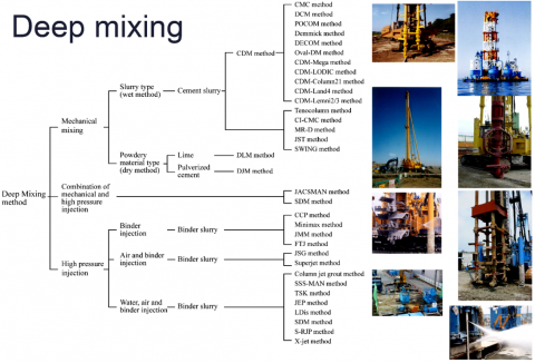
Due to complex influencing conditions, the issue of soil carrying capacity becomes crucial when structures must be built on soft and low strength soil deposits. As a result, various ground improvement methods for increasing soil strength parameters have been devised [1]. Enhancing a soil's physical/mechanical properties without altering its natural composition is referred to as soil improvement. The soil subbase is improved using knitted materials or other methods that link soil particles. In the 1970s, Japan developed the DSM (Deep Soil Mixing) column process (Figure 1). The primary purpose of cement-soil columns is to enhance the properties of local soils (such as strength and stiffness) by adding different cementing materials. The most often used binders are cement and lime [2, 3].
DMT is one of the most common and yet relatively recent methods of improving the strength and deformation characteristics of weak soil layers. This method can be used in fine sand and highly organic soils. The procedure of DMT includes mixing the in-situ soil with a certain proportion of cement or lime or a combination of both in slurry or powder form, depending on the initial water content. This is achieved by using special augers and vertical columns of improved soil with the desired center to center distance re eventually formed. If the binders are used in the slurry form, the method is called “wet DMT”; on the other hand, if they are used in powder form, it is called “dry DMT”. The latter is only applicable where the water table is near the ground surface. The effectiveness of DMT in the enhancement of soil strength was the motivation behind several comprehensive studies on different aspects of this technique from basic concepts to applications [4-9].
Lime is frequently used to strengthen cohesive soil. The shear strength of the stabilized soil gradually increases over time. This increase in strength is influenced by soil type, lime content, lime type, the density of the compacted material, and curing conditions, including the period between mixing and compaction of the soil. Lime columns can be used to support light constructions or to strengthen road embankments. The columns and the soil contained by the columns from a more or less stiff block, with minor differential settlements within the block [10]. Fundamental metrics such as after-curing void ratio (eot) and cement content (Aw) have been proven to be adequate for characterizing the strength and compressibility of cement-admixed clay at high water contents. The ratio eot/Aw has been proved to integrate the effects of clay water content, cement content, and curing time on the strength of cement-admixed clay based on analysis made on the results of unconfined compression tests [11].
Unconfined compression experiments have traditionally been performed on lime and cement-treated soft clays with parametric variations in the additive amount and curing time. The pioneering work on lime-treated clays in three-dimensional systems is summarized under untrained, drained, isotopically, and anisotropic circumstances. The (p, q, e) plot as typically applied for the understanding of triaxial data presents all data. The break-up of the cement bonds is observed with increased normal stress and the stress of the deviator. The loss of strength from highest to critical conditions with increasing shear stress is also shown [12]. The 55-kilometer Bangna-Bangpakong Highway in Thailand has severe settlement and stability issues. The deep mixing technique (DMM) with soil-cement utilizing conventional Portland cement was used for foundation enhancement on this major arterial road. The shear strength of the surrounding soft clay (soil failure) or the shear strength of the cement pile regulates the bearing capacity of a single cement pile (pile failure). Settlement assessments of treated ground were performed for cement pile lengths of 14, 16, and 18 m at 1.5, 1.7, and 2.0 m spacing. The 1.5 m spacing results in the least amount of settlement and the most significant settlement decrease [13]. Swelling of expansive soils and related foundation movements causes many structures considerable problems. With the enormous clays that exist in Ankara. In order to increase the physical properties, swelling, strength and strength consolidation of that clay, the performance of the lime column approach was examined on laboratory size models [14].
Figure 1. Deep mixing methods [3]
Comprehensive laboratory and field study program to design a five-hectare area of land growth using DSM are explored. Site inspection, drilling, sampling, and field testing using CPTU and VST were all included in the scope of work. The laboratory research was undertaken to optimize the mix structure and consistency of the cement [15]. State-of-the-art and recent advances in Deep Soil Mixing, emphasizing the European perspective is discussed. The debate is accompanied by a short review of significant historical developments that have retained their importance until recently an updated general classification scheme for Soil Mixing that allows a comprehensive understanding of the old and new machinery and machines designed and improved soil. The focus is on wet soil mixing and its application to concrete foundations such as highway and railway viaducts and modern wind turbines [16]. The spatial correlation effects on the overall behavior of a finite element analysis axially loaded column, in which the strength and the module of the material are regarded as random fields. The mean and standards difference in the general strength of a full-sized column might be easily achieved with this method. Therefore, in determining design values these results are likely to be more scientific [17]. Two full-scale experiments to determine lime-cement column panels' field behavior as excavation support are conducted. Both of these experiments began with the excavation of a braced steel sheet pile wall backed by panels of alternating lime-cement columns to a predetermined depth, followed by a stepwise increase in the load added behind the sheet pile wall. These experiments demonstrated that column-type ground improvement constructed as panels of alternating columns within the passive zone of a sheet pile wall significantly improves stabilization and decreases structural stresses, vertical and horizontal displacements in the soil caused by excavation and stacking [18]. Montmorillonite's (MMT) impact on the bearing potential of soft soil reinforced by the columns of cement-deep mix (CDM) is designed for the simulation of laboratory model. The findings indicated that soil concrete specimens practically linearly decrease in their MMT content, an unconfined compressive strength. The bearing capacity is reduced when the MMT concentration increases[19].
2.1 Testing program
The current research included thirteen laboratory models, one of which was for untreated soft clay soil. Four soil models were treated in labs using cement columns utilizing the dry method. Four model tests were carried out to evaluate the soft clay soil after it had been treated with dry lime columns. The mat foundation has been strengthened with a pile foundation to accommodate the conduct of the last four model tests on the mat foundation, the model tests were carried out using single, double, three, and four cement/lime columns or piles, according to the chosen layout. All model tests have been conducted twice to verify the accuracy of the test results. To accomplish this, three soil specimens have been prepared and two have been tested for all investigations. The gap between results was confined to less than 5%. If it exceeded 5 %, the third specimen was tested and the average findings were obtained, unless the data were removed.
2.2 Materials
2.2.1 Soil
The study results revealed that 10% sand and 38% silt, and 52% clay were used in carrying up the model tests. The soil is inorganic sandy silt clay called CL, according to the Unified Soil Classification System. The physical properties of the soil are presented in Table 1.
Table 1. Soil Characteristics
|
Property |
Value |
Standard |
|
Liquid limit, L.L. (%) |
42 |
ASTM D4318 [20] |
|
Plastic limit, P.L. (%) |
25 |
ASTM D4318 |
|
Plasticity index, P.I. (%) |
17 |
ASTM D4318 |
|
Specific Gravity |
2.66 |
ASTM D854 [21] |
|
Maximum dry unit weight (kN/m3) |
19.30 |
ASTM D698 [22] |
|
Degree of Saturation |
100% |
|
|
Optimum moisture content |
14% |
ASTM D2216 [23] |
|
Sand content |
10% |
|
|
Silt content |
38% |
|
|
Classification (Unified Soil Classification System) |
CL |
ASTM D2487 [24] |
2.2.2 Cement
This investigation made use of sulfate-resistant Portland cement. The properties of the cement used according to Standard Test Methods for Chemical Analysis of Hydraulic Cement, ASTM, C114 – 11a are mentioned in Table 2 [25].
Table 2. Cement Properties
|
Property |
Value |
|
Chemical Properties |
|
|
SiO2 |
22.40 |
|
Al2O3 |
3.75 |
|
Fe2O3 |
4.50 |
2.2.3 Lime
As a stabilizer, a commercial quick lime was utilized in this experiment; the physical and chemical properties of the lime employed are listed in Table 3 according to Standard Specification for Quicklime and Hydrated Lime for Soil Stabilization, ASTM C 977 – 03 [26].
Table 3. Cement Properties
|
Property |
Value |
|
CaO (%) |
88.40 |
|
MgO (%) |
1.75 |
|
Carbon Dioxide |
3.45 |
|
Free Moisture% |
0 |
|
Retained on (24.4-mm) sieve |
0 |
2.3 Configuration of the test
2.3.1 Soil tank
The model tests were conducted in a steel test tank with dimensions of 500 mm x 500 mm x 500 mm and constructed of steel plates 6 mm in thickness as shown in Figure 2. The container is sufficiently stable and demonstrated no lateral deformation during soil preparation and testing.
2.3.2 The loading frame
The entire configuration, mainly consisting of the steel container, loading frame, Linear variable differential transducer (LVDT), 0.001 mm accurate, loading cell with a capacity of 50 kN, logger data, and accessories, is illustrated in Figure 2.
Figure 2. Complete setup
2.3.3 The foundation plates and accessories
The model tests were conducted on a square steel plate 150 mm wide and 10 mm thick that served as the square foundation.
2.4 Model preparation and testing
A correlation between the water content and the soil's undrained shear strength was established prior to creating the soil bed. This association would aid in sustaining the required shear intensity for each model. The shear strength was determined using the unconfined compression test. In this research, the soil was produced at a moisture content of 28.2 percent, which corresponds to undrained shear strength, cu of 13 kPa (ASTM D 2166 [27]). Following that, the soil bed was prepared as follows: To begin, the natural soil was smashed with a hammer into small pieces and then allowed to air dry for 24 hours. Second, the soil sample was split into 10-kilogram portions and sufficiently moistened. Following that, samples of moist clay soil were gathered in a large container and left to soak for five days. During the period, the everyday temperature was monitored. After the required saturation period had ended, the test tank was filled with saturated clay soil in 10-cm-thick layers. To reach the necessary density of 18.25 kN/m3, each layer was tamped with a special tamping hammer weighing 2 kg and measuring 50 mm x 50 mm. The soil model's final thickness was 400 mm.
2.5 Construction of pile, cement, and lime columns
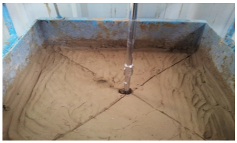
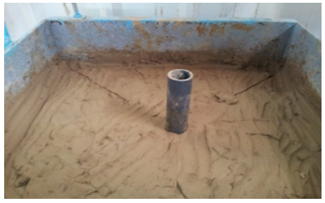
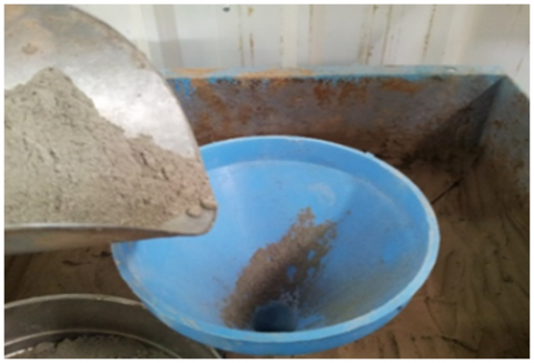
To begin, the soil bed's top layer was flattened. Later, a pile or piles of 30 mm in diameter and 400 mm in length (i.e., a length to diameter or (L/D) ratio of 13.33 was pressed into the soil block to the desired depth. The (L/D) ratio of the pile is an important factor in determining the pile's bearing capacity. This ratio was chosen for the pile model to fit the dimensions of the square foundation, which serves as a cap for the piles in this case, as well as to match the dimensions of the steel container. In the field applications, a hollow tube is driven into the ground to the required depth, and the binding agent is delivered with air pressure into soil holes, cracks, fissures, and crevices as the tube is removed [28]. The method has been replicated with groups of columns installed in the compact soil block. To construct the column, an auger was used to make the hole to a depth of 400 mm. Each was installed in blocks of soil using a hollow polyvinyl chloride (PVC) pipe, which was opened on both ends, of 30 mm of diameter and 550 mm height. The PVC length has been selected to help the soil block penetrate easily, creating the columns with the features of the compact soil blocks. The advance of utilizing a PVC pipe was to make smooth holes in the soil block without the need of spiral brush cleaning the holes before lime or cement was filled with [14]. The columns were then filled with a homogenous amount of powdered cement or quicklime. To form the lime piles, three successive uniform layers of cement or quicklime were placed and lightly compacted. The center-to-center space between each pile and the next pile was 100 mm. The installation of a single column within a compacted soil block in the test tank is depicted in Figures 3 to 5.
Figure 3. Drilling the hole
Figure 4. Insertion the PVC
Figure 5. Fill the hole with cement or lime powder
2.6 Model testing procedure
At the end of the 24 hours, the footing assembly was placed in position so that the center of the footing coincides with the center of the soil bed for all model tests (single or groups of pile and cement or lime columns). Meanwhile, the incremental load of 50 N was then applied centrally on the footing. Each incremental load was left for (4 minutes) or until the settlement was no longer consistent, whichever came first according to (ASTM. 2013a.). In the following step, a linear variable optical transformer with a resolution of 0.001 mm was installed on the foundation to document the settlement at the ending of the period for each incremental load.
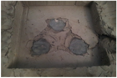
Figure 6. Three columns group after testing
Furthermore, the incremental load was added until the settlement reached approximately equal to 22 percent of the width of the footing, or about 33 mm, exceeding the permissible settlement limit for the purpose of studying the stress-strain relationship. Figures 6 to 9 show the column groups after testing.
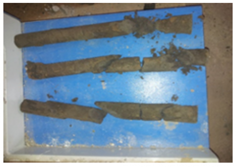
Figure 7. Three columns group after extraction from the soil
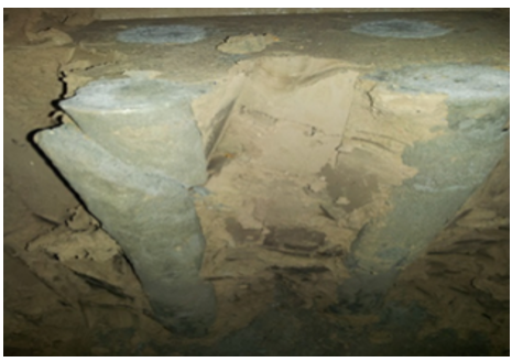
Figure 8. Four columns group after testing
Figure 9. Three columns group after extraction from the soil
3.1 Definition of failure load
A single model test was conducted on an untreated saturated soft clay soil. The footing was placed on the soil surface and gradually loaded until failure. The effects of applied pressure in (kN/m2) vs. settlement ratio (S/B) (where S represents footing settlement and B represents footing width) are shown in Figure 10. As shown in the graph, the settlement ratio increases approximately linearly with increasing stress. This action was predicted, as an increase in load would enhance the rate of consolidation and produce the settlement, as many studies hypothesized. Local shear failure appears to be the mechanism of failure (Figure. 10). There have been numerous methodologies provided for defining the ultimate bearing capacity and failure of shallow foundations. The following are the two most important:
Figure 10. Applied pressure versus settlement ratio (S/B) for a footing resting on untreated soil
Terzaghi's 1947 suggestion, in which failure was defined at a load equal to 10% of the model footing width (or pile diameter). Numerous researchers have endorsed this proposal.
Tangent proposal, in which failure is defined as the point at which the two tangents of the load-settlement curve connect. The first is tangent to the curve's beginning portion, while the second tangents to the curve's bottom flatter component.
The schematic design utilized to determine the failure load in both ways is shown in Figure 10, with the Terzaghi method yielding a value of 106 kN/m2 and the Tangent method yielding a value of 122 kN/m2.
When applying the Terzaghi equation to determine the ultimate bearing capacity of a shallow foundation on saturated clay soil, the result is:
$Q_{u l t .}=c N_{c}$
Qult. $=17 \times 5.7=96.9 \mathrm{kN} / \mathrm{m}$ (1)
While the ultimate bearing capacity of the soil as determined by the Hansen technique is Qult. =17 x 5.14=87.38 kN/m.
Because the ultimate bearing capacity determined from a criterion of 10% B settlement failure is comparable to Terzaghi's method for predicting failure load, this method will be used to calculate the maximum load that the model footing can withstand.
3.2 Discussion of results (SRR and BIR)
The remolded soil sample had a shear strength of 13 kN/m2 and was placed in a cubic soil test tank with a side length of 50 cm and a square footing with 15 cm side. Based on the testing program, the model tests were divided into four categories to determine the influence of deep foundations and deep maxing method (DMM) as one of the technical approaches for enhancing soft soil qualities on bearing capacity and settling, as follows:
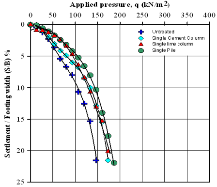
For an untreated soft clay soil sample, one model test was performed. Four soil model tests were conducted by using a deep foundation model, initially using a single pile and then groups of columns (two, three, and four). Four model tests were carried out for soil treated by a single cement column using the dry method, followed by a group of columns (two, three, and four) . A single lime column was used to treat soil using the dry method, followed by (two, three, and four) groups of lime columns. The fitting of a polynomial of degree four is used to draw the curve connecting the real points in Figure 11; additionally, the style is used in all subsequent figures. Figure 11 depicts the distinct difference in behavior between untreated soil and soil treated with a single pile, cement column, or lime. This is visible when the settlement is analyzed using the settlement reduction ratio (SRR), equal to the settlement of untreated soil divided by the settlement of soil reinforced with a pile or column of cement or lime. Looking at Table 4, it was evident that while employing a single pile, the averaged settlement reached half at the failure load level, whereas the SRR of soil treated with a cement or lime column fell at an average of 32%.
To determine the influence of a single pile, cement column, or lime on bearing capacity, a factor known as the bearing improvement ratio (BIR) was utilized, which equals the treatment soil bearing capacity to the bearing capacity of the natural soil without any treatment. Terzaghi's assumption was used to calculate the bearing capacity at failure corresponding to a drop equal to 10% of the foundation's width. The BIR can be calculated using the previous definition as shown in the following equation.
Table 4. Settlement reduction ratio (SRR) for single and groups of the pile, cement, and lime columns
|
No. of column |
Pile |
Cement Column |
Lime Column |
|
Single |
52.0% |
30.8% |
34.8% |
|
Two |
83.3% |
67.0% |
68.8% |
|
Three |
87.4% |
87.0% |
87.0% |
|
Four |
93.4% |
89.5% |
88.4% |
$\mathrm{BIR}=\frac{\mathrm{Q}_{\mathrm{utr}}}{\mathrm{Q}_{\mathrm{u}}}$ (2)
where, Qutr denoted the ultimate bearing capacity of soil founded on a pile or treated with cement or lime columns, and Qu denoted the ultimate bearing capacity of soil founded on a square footing without any treatment.
The table clearly shows a convergence in the percentage of increase in bearing capacity when employing a single pile, cement column, or lime column, and it is roughly equivalent to 20%. To determine the influence of a single pile, cement column, or lime on bearing capacity, a factor known as the bearing improvement ratio (BIR) was utilized, which equals the treatment soil settlement to the settlement of the natural soil without any treatment.
Terzaghi's assumption was used to calculate the bearing capacity at failure corresponding to a drop equal to 10% of the foundation's width. Table 5 clearly shows a convergence in the percentage of increase in bearing capacity when employing a single pile, cement column, or lime column, and it is roughly equivalent to 20%.
Table 5. Bearing improvement ratio (BIR) for single and groups of the pile, cement, and lime columns
|
No. of column |
Pile |
Cement Column |
Lime Column |
|
Single |
1.23 |
1.20 |
1.20 |
|
Two |
2.00 |
1.50 |
1.60 |
|
Three |
2.27 |
2.33 |
2.27 |
|
Four |
2.83 |
2.43 |
2.43 |
Figure 11. S/B versus applied pressure for single pile and cement column
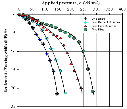
A load is imparted to two piles or two cement columns or lime, as shown in Figure 12. According to Table 3, the percentage of settlement reduction was doubled when compared to employing a single pile or column. As a result, the settlement reduction ratios for piles, cement columns, and lime columns, correspondingly, were 83.3%, 67.0%, and 68.8%respectively. The bearing capacity doubled due to utilizing two piles, and this BIR ratio was increased to 1.50 for cement columns and 1.60 for lime columns (Table 5). With the increase in the surface area of the material with increased hardness، the effect becomes more pronounced. In terms of settlement and bearing coefficients, cement, and lime columns have made great strides forward.
Figure 12. S/B versus applied pressure for two piles and cement columns
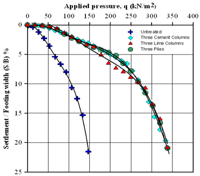
When three piles or three columns of cement or lime are used. As shown in Tables 4 and 5 and Figure 13, the growth in the ratios of decreasing settlement and increasing carrying capacity followed the same pattern as in Figures 11 and 12. Additionally, it was noted that the improvement values in the prior two ratios were very similar for all three approaches. The average percentage of settlement was 87%. The relative rigidity of the columns in the untreated soil between the columns governs the block's settlement (soil + cement or lime column). In this configuration, the carrying capacity rose by 130%.
Figure 13. S/B versus applied pressure for three piles and cement columns
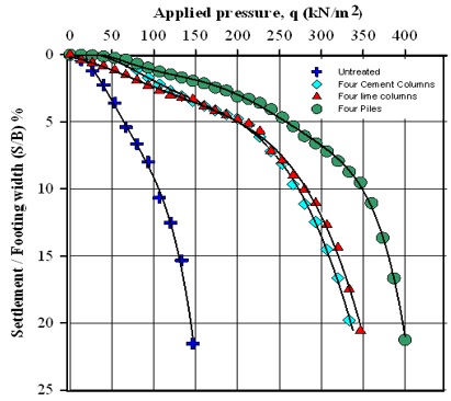
When the number of piles was increased to four (Figure 14), the settlement reached the lowest value in all preceding groups, with an average (SRR) of 93% for all load levels when compared to untreated soil, while the (SRR) was 89% percent for soil treated with cement columns and nearly identical when using lime columns. This related to the stiffness of the reinforced soil block encompassed by the cement or lime columns determine the settlement of constructions supported by cement or lime columns and the load from the structure will be transferred to the surrounding soil around the block's perimeter prior to the consolidation of the soil beneath or around the block [10].
Figure 14. S/B versus applied pressure for three piles and cement columns
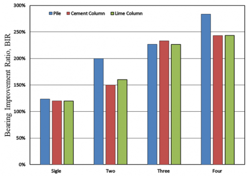
While the bearing capacity of these groups increased by 1.43 times for cement or lime columns and by 1.83 for piles. In addition, here is evidence of the efficacy of cement and lime column techniques in significantly increasing the bearing capacity of soft clay soil in proportions comparable to those achieved with deep foundations represented by piles. When economics are considered, cement and lime are a viable economic alternative, particularly in developing countries experiencing a large reconstruction movement, due to their low cost and ease of implementation in comparison to deep foundations, which are more expensive and require complex implementation methods, particularly in loose and soft soils. Not to mention the fact that raw materials are abundant naturally and need little work to extract, particularly the component known as lime, which is abundantly available in Iraq and throughout the world. The widespread usage of lime in ancient ages, most notably in the Abbasid era's palaces, demonstrates this clearly. Additionally, the techniques of cement and lime columns contribute to the continual development of the qualities of the soft soils found throughout central and southern Iraq. All values of the settlement reduction ratio and bearing improvement ratio for all groups of piles, cement columns, and lime columns are presented in Figures 15 and 16.
Figure 15. Settlement Reduction Ratio, (SRR) for Piles, cement and lime columns
Figure 16. Bearing improvement ratio (BIR) for piles, cement and lime columns
3.3 Efficiency(η)of pile, cement and lime column groups
Efficiency(η)of Pile, Cement and Lime Column Groups Similarly to piles, the efficiency of a group (E) of cement or lime columns is defined as the ratio of the group's capacity to each individual cement or lime column multiplied by the number of columns in the group. On how much load a single pile of cement or lime column could carry, and how much load could be carried by a group of cement or lime columns with a settlement of 10% B, was determined using the formula:
$\eta=\frac{Q_{n}}{n Q_{s}}$ (3)
where, η = efficiency of the pile, cement or lime group; Qg = axial capacity of pile group; Qs= axial capacity of single pile; n = number of piles, cement or lime in group.
Table 5 illustrates the ultimate load of single and multiple piles, cement, and lime in response to a 10% B settling (B: width of footing). Table 6 shows the calculations of group efficiency for all model tests. It can be seen from these tables that the group efficiency is decreased with increasing the numbers of pile and cement or lime column. For example, the group efficiency of two, three, and four cement columns are (0.63, 0.0.65, 0.51). These tables demonstrate that the efficiency of lime column groups is approximately similar to cement columns. Table 7 shows that the group efficiency values of pile groups are larger than the soil improvement techniques, cement, and lime columns groups.
Table 6. The ultimate load of single and groups of the pile, cement, and lime columns
|
No. of column |
Pile, N |
Cement Column, N |
Lime Column, N |
|
Single |
3700 |
3600 |
3600 |
|
Two |
6000 |
4500 |
4800 |
|
Three |
6800 |
7000 |
6800 |
|
Four |
8500 |
7300 |
7300 |
Table 7. The efficiency of groups of the pile, cement, and lime columns
|
No. of column |
Pile |
Cement Column |
Lime Column |
|
Two |
0.81 |
0.63 |
0.67 |
|
Three |
0.61 |
0.65 |
0.63 |
|
Four |
0.57 |
0.51 |
0.51 |
(1) The implementation of the technique of deep mixing (DMM) utilizing cement columns or lime by the dry method to improve the soft clay soil resulted in a considerable reduction in sinking as well as a significant increase in bearing capacity.
(2) The settlement reduction ratio (SRR) while using pile foundations in soft clay soil was equal to 52% at the failure load level, however settlement in clay soil samples treated with cement or lime column was reduced by an average of 32 percent. When the preceding approaches were utilized, the bearing capacity improved by about 20%.
(3) When groups of two cement or lime columns are used instead of a single column, the SRR value is doubled. The bearing capacity was doubled due to the usage of two piles. Also, for soil treated with cement or lime columns, it increased by 1.50 and 1.6 times, respectively.
(4) In the context of all groups, the settlement value for the four-pile group (an averaged SRR of 93% for all load levels compared to untreated soil) was lower than for previous groups, while the settlement value for the soil treated with cement columns and lime columns (an SRR of 89%) was nearly identical. In the same manner, the bearing capacity of these groups improved by 143% for cement and lime columns and 183% for piles.
(5) According to the results of the examination models for each of the cement and light columns, there is no discernible difference between them in terms of improving bearing capacity and reducing settlement of the soil treated with each of them.
The efficiency of the group decreases as the number of columns grows. Two, three, and four cement columns have group efficiency of (0.63, 0.0.65, 0.51). Furthermore, pile groups have higher group efficiency values than soil improvement approaches, cement, and lime column.
[1] Hirkane, S.P., Gore, N.G., Salunke, P.J. (2014). Ground improvement techniques. International Journal of Inventive Engineering and Sciences, 2(2): 11-13.
[2] Egorova, A.A., Rybak, J., Stefaniuk, D., Zajączkowski, P. (2017). Basic aspects of deep soil mixing technology control. In IOP Conference Series: Materials Science and Engineering, 245(2): 022019. https://doi.org/10.1088/1757-899X/245/2/022019
[3] Kitazume, M. (2017). Deep mixing method, The Japanese experience and recent advancement. HKCI seminar, Tokyo Institute of Technology.
[4] Hosseini, S.A.A., Mojtahedi, S.F.F., Sadeghi, H. (2020). Optimisation of deep mixing technique by artificial neural network based on laboratory and field experiments. Georisk: Assessment and Management of Risk for Engineered Systems and Geohazards, 14(2): 142-157. https://doi.org/10.1080/17499518.2019.1612526
[5] Porbaha, A. (1998). State of the art in deep mixing technology: Part I. Basic concepts and overview. Proceedings of the Institution of Civil Engineers-Ground Improvement, 2(2): 81-92. https://doi.org/10.1680/gi.1998.020204
[6] Porbaha, A., Tanaka, H., Kobayashi, M. (1998). State of the art in deep mixing technology: Part II. Applications. Proceedings of the Institution of Civil Engineers-Ground Improvement, 2(3): 125-139. https://doi.org/10.1680/gi.1998.020303
[7] Porbaha, A., Shibuya, S., Kishida, T. (2000). State of the art in deep mixing technology. Part III: Geomaterial characterization. Proceedings of the Institution of Civil Engineers-Ground Improvement, 4(3): 91-110. https://doi.org/10.1680/grim.2000.4.3.91
[8] Bergado, D.T., Lorenzo, G.A. (2005). Economical mixing method for cement deep mixing. In Innovations in Grouting and Soil Improvement, pp. 1-10. https://doi.org/10.1061/40783(162)12
[9] Larsson, S., Dahlström, M., Nilsson, B. (2005). Uniformity of lime-cement columns for deep mixing: A field study. Proceedings of the Institution of Civil Engineers-Ground Improvement, 9(1): 1-15. https://doi.org/10.1680/grim.9.1.1.58541
[10] Broms B.B., Boman P. (1977). Stabilization of soil with lime columns. Royal Institute of Technology, Stockholm. https://doi.org/10.1007/978-1-4615-3928-5_24
[11] Lorenzo, G.A., Bergado, D.T. (2004). Fundamental parameters of cement-admixed clay—New approach. Journal of Geotechnical and Geoenvironmental Engineering, 130(10): 1042-1050. https://doi.org/10.1061/(ASCE)1090-0241(2004)130:10(1042)
[12] Balasubramaniam, A.S., Buensuceso, B.R., Oh, E.Y., Bolton, M., Bergado, D.T., Lorenzo, G.A. (2005). Strength degradation and critical state seeking behaviour of lime-treated soft clay. Deep Mixing, 5: 35-40.
[13] Bergado, D. T., Ruenkrairergsa, T., Taesiri, Y., Balasubramaniam, A.S. (1999). Deep soil mixing used to reduce embankment settlement. Proceedings of the Institution of Civil Engineers-Ground Improvement, 3(4): 145-162. https://doi.org/10.1680/gi.1999.030402
[14] Tonoz, M., Gokceoglu, C., Ulusay, R. (2003). A laboratory-scale experimental investigation on the performance of lime columns in expansive Ankara (Turkey) clay. Bulletin of Engineering Geology and the Environment, 62(2): 91-106. https://doi.org/10.1007/s10064-002-0176-z
[15] Ortigao, A., Falk, E., Felix, M., Koehler, T. (2015). Deep soil mixing trials at Porto Alegre airport, Brazil. In Deep Mixing Conference, pp. 997-1004.
[16] Topolnicki, M. (2016). General overview and advances in Deep Soil Mixing. In XXIV Geotechnical Conference of Torino Design, Construction and Controls of Soil Improvement Systems, pp. 25-26.
[17] Namikawa, T., Koseki, J. (2013). Effects of spatial correlation on the compression behavior of a cement-treated column. Journal of Geotechnical and Geoenvironmental Engineering, 139(8): 1346-1359. https://doi.org/10.1061/(ASCE)GT.1943-5606.0000850
[18] Ignat, R. (2018). Ground improvement by dry deep mixing lime-cement column panels as excavation support (Doctoral dissertation, KTH Royal Institute of Technology).
[19] Tuan, N.A., Thang, N.N. (2019). Cement deep mixing method of soil stabilization effecting of montmorillonite content on the bearing capacity of ground improvement. International Journal of Civil Engineering and Technology, 10(12): 440-449.
[20] ASTM, D. (2007). Standard test method for particle-size analysis of soils. West Conshohocken: American Society for Testing and Materials. https://doi.org/10.1520/D0422-63R07E02
[21] ASTM D854. (2005). Standard test method for specific gravity of soil solids by water pycnometer. West Conshohocken: American Society for Testing and Materials. https://doi.org/10.1520/D0854-05
[22] ASTM D2487. (2000). Standard practice for classification of soils for engineering purposes (Unified Soil Classification System). West Conshohocken: American Society for Testing and Materials. https://doi.org/10.1520/D2487-00
[23] ASTM, D. (2006). Standard test method for unconfined compressive strength of cohesive soil. ASTM standard D, 2166. https://doi.org/10.1520/D2166_D2166M-16
[24] ASTM D1143, A. (2013). Standard test methods for deep foundations under static axial compressive load. West Conshohocken, PA, ASTM International. https://doi.org/10.1520/D1143_D1143M-20
[25] Bowles, J.E. (1992). Engineering Properties of Soils and Their Measurement. 4th Edition, McGraw-Hill. https://doi.org/10.1111/j.1752-1688.1971.tb05035.x
[26] ASTM, C. (2016). Specification for quicklime and hydrated lime for soil stabilization. Annual Book of ASTM Standards, pp. 1-6. https://doi.org/10.1520/C0977-03
[27] ASTM, C114. (2018). Standard test methods for chemical analysis of hydraulic cement. West Conshohocken. American Society for Testing and Materials. https://doi.org/10.1520/C0114-18
[28] Rogers, C.D.F., Glendinning, S. (1997). Slope stabilisation using lime piles. In Ground Improvement Geosystems Densification and Reinforcement: Proceedings of the Third International Conference on Ground Improvement Geosystems London, pp. 174-180.