Yahia Laamari* | Samia Allaoui | Abdelmalik Bendaikha | Salah Saad
© 2021 IIETA. This article is published by IIETA and is licensed under the CC BY 4.0 license (http://creativecommons.org/licenses/by/4.0/).
OPEN ACCESS
The main idea of this article is to model and analyze the short circuit fault between the turns of the stator windings of a Permanent Magnet Synchronous Motor (PMSM). To accomplish this objective, a numerical model describing both the healthy and defective state of the PMSM is developed. Besides, this dynamic model is simulated and tested to study motor behavior under different fault conditions. Also, the frequency domain analysis based on the famous fast Fourier transform (FFT) as well as the time-frequency analysis using discrete wavelet transform (DWT) is established. This allowed extracting signatures related to the presence of an inter-turn short-circuit (ITSC). In the proposed method, ITSC detection is based on the decomposition of stator currents and electromagnetic torque. DWT and spectral analysis show that the low-frequency wavelet details as well as the total harmonic distortion (THD) can be easily used as a good short-circuit indicator. The simulation results of a healthy and faulty motor show the effectiveness of these two approaches but with a significant superiority of the DWT over the FFT.
PMSM, fault detection, modeling, inter-turn short circuit, fast Fourier transform, discrete wavelet transform
The PMSM has attracted attention in several industrial applications such as production systems, machine tools vehicular propulsion and industrial drives [1, 2]. This attraction is due to their high efficiency, large torque to inertia ratio, high power density. Hence, the PMSM is known for having superior dynamic performance and is often chosen for high performance applications [3, 4]. However, since the motor is operating in hardened environment conditions with various stresses, affected by the power supply and load conditions, PMSM is at risk of some failures that will inevitably occur during the long-term continuous working [5, 6]. PMSM failures are mainly classified into three parts, electrical, mechanical and magnetic failures.
The stator ITSC is one of the most common electrical faults in PMSM. According to reference [7], a short circuit fault is 30% to 40% of faults in PMSM. This kind of fault is caused by the combination of diverse stresses acting on the stator winding, such as mechanical, thermal, electrical, and environmental stresses. These effects are accelerated in electrical machines supplied by inverters [7-12].
The stator winding failures of the PM motor produce a large current flowing in the shorted turns. This failure must be detected and identified rapidly to avoid disastrous damage. Fault diagnosis and condition monitoring of PMSM problems are important to guarantee its availability and durability with high operating performances. Under stator winding faults, the motor performances become poor. Hence, some authors have studied and validated experimentally the proposed models using Matlab/Simulink [8, 11]. In fact, various modeling approaches were developed to analyze the ITSC influence on the synchronous machine in both healthy and faulty states [4, 13]. Equivalent circuit models are useful to investigate and explore the system dynamics and the advantage of being faster in time computing [8].
In this context, different approaches are proposed to detect and identify the inter-turn faults in electrical machines. The present study will be focused on the ITSC fault diagnosis in the stator windings of PMSM drive. The signals obtained from the motor are processed by the most common ITSC detection method to distinguish the difference between healthy and faulty PMSM state. This method can distinguish the performance of failures and extract their features from stator current and vibration signals [6, 11].
In signal processing, the conventional analyzing tool is FFT. With this method, a signal (i.e. stator current or torque signal) is decomposed in linear combination of waves with different frequencies, so the FFT can easily give us the overall frequency information contained in a signal [14, 15]. However, sometimes it is difficult to locate clearly the features corresponding to certain faults by applying FFT method. In addition, due to the loss of time information, the FFT can only be used to process a stationary signal. Consequently, certain time-frequency techniques as short-term Fourier transformation (STFT), wavelet transformation (WT) and empirical wavelet transformation (EWT) have currently attracted the attention of many researchers [15-18].
In recent years, discrete wavelet transform (DWT) has been widely utilized in signal processing applications, giving the time-evolution of the signal at different scales [17]. Many papers have been published on applying DWT in faults diagnosis in electromechanical machines [16, 18].
In some situations, immediate detection of short circuit faults between turns is necessary and time-frequency analysis is a better choice than frequency analysis.
In this work, ITSC detection is mainly based on decomposition of PMSM electromagnetic torque and stator currents by DWT where the wavelet coefficients of these signals have been extracted. In addition, THD value can be used also as an indicator of fault detection. Simulation results are presented under different inter-turn faults and severity conditions.
The present paper describes the dynamic model of the PMSM under stator winding fault in the stationary abc and αβ references frames. The simulation results of the proposed PMSM model with ITSC fault detection have showed the effectiveness of these techniques.
The PMSM stator under inter-turn fault winding is illustrated in Figure 1. In this representation, resistance, self-inductance and back EMF are considered. In addition, the mutual inductance in the same phase between the winding in short circuits and the winding in healthy state also needs to be taken into account [13, 19].
An ITSC indicates a breakdown between two stator windings in the same phase. In order to take into consideration this failure in the PMSM model, the phase affected (as), is partitioned in two sub-windings representing the healthy and faulty branch of the phase winding, respectively.
The ITSC failure is modeled by a resistance with a value depending on fault severity [8, 9]. When this value decreases near zero, the insulation faults increase to an inter-turn full short-circuit value. The growth between ∞ and zero is very fast in the majority insulation materials [8, 10]. The fault current flowing through the fault resistance (Rf) is called (if). So, to clearly represent the default size, a new parameter (µ) is introduced. This parameter is defined as the ratio between the numbers of turns in short circuit (Nf) and the total number of turns in a phase (Ns). The severity of this fault is characterized by two parameters, short circuit percentage (µ) and fault resistance (Rf).
The resistances of healthy and faulty parts of stator winding are expressed by the following equations:
$\left\{ \begin{align} & {{R}_{as1}}=(1-\mu ){{R}_{as}}\text{ and }{{R}_{as2}}=\mu {{R}_{as}} \\ & \mu =\frac{{{N}_{as2}}}{{{N}_{as1}}+{{N}_{as2}}}=\frac{{{N}_{f}}}{{{N}_{s}}} \\\end{align} \right.$ (1)
Figure 1. PMSM stator with ITSC in phase (as)
2.1 Fault model of PMSM in abc frame reference
To build the mathematical model of the PMSM drive, we the following simplifying assumptions are adopted: The magnetic circuit has no saturation effects; the influence of temperature on parameters is neglected. The distributed of magnetic motive force and the flux profiles are considered sinusoidal and higher harmonics are neglected [12].
The voltage equations of PMSM with an ITSC fault in phase (as) as illustrated in Figure 1 can be written in abc-frame as follows:
$\left\{ \begin{align} & {{v}_{as1}}={{R}_{as1}}\text{ }{{i}_{as}}+{{L}_{as1}}\frac{d}{dt}{{i}_{as}}+{{e}_{as1}}+{{M}_{a1a2}}\frac{d}{dt}\left( {{i}_{as}}-{{i}_{f}} \right)+{{M}_{a1b}}\frac{d}{dt}{{i}_{bs}}+{{M}_{a1c}}\frac{d}{dt}{{i}_{cs}} \\ & {{v}_{as2}}={{R}_{as2}}\text{ }\left( {{i}_{as}}-{{i}_{f}} \right)+{{L}_{as2}}\frac{d}{dt}\left( {{i}_{as}}-{{i}_{f}} \right)+{{e}_{as2}}+{{M}_{a1a2}}\frac{d}{dt}{{i}_{as}}+{{M}_{a2b}}\frac{d}{dt}{{i}_{bs}}+{{M}_{a2c}}\frac{d}{dt}{{i}_{cs}} \\ & {{v}_{bs}}={{R}_{bs}}\text{ }{{i}_{bs}}+L\frac{d}{dt}{{i}_{bs}}+{{e}_{bs}}+\left( {{M}_{a1b}}+{{M}_{a2b}} \right)\frac{d}{dt}{{i}_{as}}+M\frac{d}{dt}{{i}_{cs}}-{{M}_{a2b}}\frac{d}{dt}{{i}_{f}} \\ & {{v}_{cs}}={{R}_{cs}}\text{ }{{i}_{cs}}+L\frac{d}{dt}{{i}_{cs}}+{{e}_{cs}}+\left( {{M}_{a1c}}+{{M}_{a2c}} \right)\frac{d}{dt}{{i}_{as}}+M\frac{d}{dt}{{i}_{bs}}-{{M}_{a2c}}\frac{d}{dt}{{i}_{f}} \\ & 0=-{{R}_{as2}}\text{ }{{i}_{as}}-\left( {{L}_{as2}}+{{M}_{a1a2}} \right)\frac{d}{dt}{{i}_{as}}-{{M}_{a2b}}\frac{d}{dt}{{i}_{bs}}-{{M}_{a2c}}\frac{d}{dt}{{i}_{cs}}-{{e}_{as2}}+ \\ & \text{ }\left( {{R}_{as2}}+{{r}_{f}} \right){{i}_{f}}+{{L}_{as2}}\frac{d}{dt}{{i}_{f}} \\\end{align} \right.$ (2)
where, Rs and L are the resistance and the self-inductance of healthy stator phases windings with Ras=Rbs=Rcs=Rs. M is the mutual inductance between phase windings for PMSM healthy state. Ras2 and Las2 are the resistance and the self-inductance of faulty sub-coil (as2). Ma1a2, Ma2b, and Ma2c are respectively the mutual inductances between the sub-coil (as1) and the coils (as2), (bs) and (cs). Also, Ma1b, Ma1c are respectively the mutual inductance between sub-coil (as1) and coils (bs) and (cs). Mab is the mutual inductance between coils (as) and (bs) [8, 19, 20].
From fault part of stator winding in Figure 1, we have:
$\left\{ \begin{align} & {{v}_{as}}={{v}_{as1}}+{{v}_{as2}} \\ & {{v}_{as2}}={{i}_{f}}{{R}_{f}} \\ & {{e}_{as2}}={{e}_{f}} \\\end{align} \right.$ (3)
As well, the following relations are normally accepted:
$\left\{ \begin{align} & {{R}_{s}}={{R}_{as}}={{R}_{as1}}+{{R}_{as2}} \\ & L={{L}_{as1}}+{{L}_{as2}}+2{{M}_{a1a2}} \\ & M={{M}_{a1b}}+{{M}_{a2b}}={{M}_{a1c}}+{{M}_{a2c}} \\ & {{e}_{as}}={{e}_{as1}}+{{e}_{as2}}={{e}_{as1}}+{{e}_{f}} \\\end{align} \right.$ (4)
In general, three phases of stator are connected in star so that: ias+ibs+ics=0. Under these conditions, the homopolar component of the current is nil and only the cyclic inductance of the motor (Ls=L-M) limits the phase currents. Therefore, from Eq. (2), Eq. (3) and Eq. (4), the dynamic voltage equations controlling the PMSM behavior with the short-circuit fault, is obtained by the following equations:
$\begin{align} & \left[ \begin{matrix} {{v}_{as}} \\ {{v}_{bs}} \\ {{v}_{cs}} \\ 0 \\\end{matrix} \right]=\left[ \begin{matrix} {{R}_{s}} & 0 & 0 & -{{R}_{as2}} \\ 0 & {{R}_{s}} & 0 & 0 \\ 0 & 0 & {{R}_{s}} & 0 \\ -{{R}_{as2}} & 0 & 0 & {{R}_{as2}}+{{R}_{f}} \\\end{matrix} \right]\left[ \begin{matrix} {{i}_{as}} \\ {{i}_{bs}} \\ {{i}_{cs}} \\ {{i}_{f}} \\\end{matrix} \right]+ \\ & \left[ \begin{matrix} {{L}_{s}} & 0 & 0 & -{{L}_{as2}}-{{M}_{a1a2}} \\ 0 & {{L}_{s}} & 0 & -{{M}_{a2b}} \\ 0 & 0 & {{L}_{s}} & -{{M}_{a2c}} \\ -{{L}_{as2}}-{{M}_{a1a2}} & -{{M}_{a2b}} & -{{M}_{a2c}} & {{L}_{as2}} \\\end{matrix} \right]\frac{d}{dt}\left[ \begin{matrix} {{i}_{as}} \\ {{i}_{bs}} \\ {{i}_{cs}} \\ {{i}_{f}} \\\end{matrix} \right]+\left[ \begin{matrix} {{e}_{as}} \\ {{e}_{bs}} \\ {{e}_{cs}} \\ -{{e}_{f}} \\\end{matrix} \right] \\\end{align}$ (5)
So, it is possible to write Eq. (5) in compact form as:
$\left[ {{V}_{abcf}} \right]=\left[ {{R}_{s}} \right]\left[ {{i}_{abcf}} \right]+\left[ {{L}_{s}} \right]\frac{d}{dt}\left[ {{i}_{abcf}} \right]+\left[ {{E}_{s}} \right]$ (6)
where, [Vabcf], [iabcf] and [Es] are the stator voltage, current and back-EMF vectors, respectively.
According to the power conservation principle, the electromagnetic torque developed by the motor under short-circuit fault between turns can be calculated by the following Eq. (7):
${{T}_{em}}=({{e}_{as}}{{i}_{as}}+{{e}_{bs}}{{i}_{bs}}+{{e}_{cs}}{{i}_{cs}}-{{e}_{f}}{{i}_{f}})/\Omega $ (7)
where,
$\left\{ \begin{align} & {{e}_{as}}=p\Omega {{\phi }_{m}}\sin (\theta ) \\ & {{e}_{bs}}=p\Omega {{\phi }_{m}}\sin (\theta -\frac{2\pi }{3}) \\ & {{e}_{cs}}=p\Omega {{\phi }_{m}}\sin (\theta +\frac{2\pi }{3}) \\ & {{e}_{f}}={{e}_{as2}}=\mu {{e}_{as}} \\\end{align} \right.$ (8)
The mechanical equation for the motor dynamics is given as:
${{T}_{em}}-{{T}_{L}}-f\Omega =J\frac{d\Omega }{dt}$ (9)
where, f is the friction coefficient; J is the rotor inertia; TL the load torque and Ω is the mechanical speed of the rotor.
The identification of the inductances of faulty motor is extremely essential because it include the failure information. Two approaches are used to calculate the faulty inductances of PMSM by taking a simple percentage of the parameters of healthy state [8-10]. In this work, we have adopted the method in which the self-inductances of the faulty and healthy branch of winding (as1, as2) are related to the square of the number of shorted turn’s windings. In addition, the mutual inductance is relative to the turn number of both parts [17]:
$\left\{ \begin{align} & {{L}_{as1}}={{(1-\mu )}^{2}}{{L}_{s}} \\ & {{L}_{as2}}={{\mu }^{2}}{{L}_{s}} \\ & {{M}_{a1a2}}=\mu (1-\mu ){{L}_{s}} \\ & {{M}_{a2b}}={{M}_{a2c}}=\mu M \\ & {{M}_{a1b}}={{M}_{a1c}}=(1-\mu )M \\\end{align} \right.$ (10)
where, μ represent the fraction of shorted turns.
2.2 Fault model in (α β) frame reference
To formulate the mathematical model for a PMSM in αβ stator stationary reference frame which takes into account the inter-turn fault windings, the extended Concordia transformation is applied [8].
$[T]=\sqrt{2/3}\left[ \begin{matrix} {1}/{\sqrt{2}}\; & {1}/{\sqrt{2}}\; & {1}/{\sqrt{2}}\; & 0 \\ 1 & {-1}/{\sqrt{2}}\; & {-1}/{\sqrt{2}}\; & 0 \\ 0 & \sqrt{{3}/{2}\;} & -\sqrt{{3}/{2}\;} & 0 \\ 0 & 0 & 0 & \sqrt{{3}/{2}\;} \\\end{matrix} \right]$ (11)
For numerical simulation, it is more convenient to express the PMSM model with ITSC fault in the state space form as follows:
$\begin{align} & \left[ \begin{matrix} {{{\dot{x}}}_{1}} \\ {{{\dot{x}}}_{2}} \\ {{{\dot{x}}}_{3}} \\\end{matrix} \right]=-{{\left[ \begin{matrix} {{L}_{s}} & 0 & {{M}_{f\alpha }} \\ 0 & {{L}_{s}} & 0 \\ {{M}_{f\alpha }} & 0 & {{L}_{as2}} \\\end{matrix} \right]}^{-1}}\left[ \begin{matrix} {{R}_{s}} & 0 & -\sqrt{{}^{2}/{}_{3}}{{R}_{as2}} \\ 0 & {{R}_{s}} & 0 \\ -\sqrt{{}^{2}/{}_{3}}{{R}_{as2}} & 0 & {{R}_{as2}}+{{R}_{f}} \\\end{matrix} \right]\left[ \begin{matrix} {{x}_{1}} \\ {{x}_{2}} \\ {{x}_{3}} \\\end{matrix} \right] \\ & +{{\left[ \begin{matrix} {{L}_{s}} & 0 & {{M}_{f\alpha }} \\ 0 & {{L}_{s}} & 0 \\ {{M}_{f\alpha }} & 0 & {{L}_{as2}} \\\end{matrix} \right]}^{-1}}\left[ \begin{matrix} {{v}_{\alpha }}-{{e}_{\alpha }} \\ {{v}_{\beta }}-{{e}_{\beta }} \\ -\mu {{e}_{\alpha }} \\\end{matrix} \right]\text{ } \\\end{align}$ (12)
where,
$\left\{ \begin{matrix} {{[{{\begin{matrix} {{x}_{1}} & {{x}_{2}} & x \\\end{matrix}}_{3}}]}^{T}}=\frac{d}{dt}{{[\begin{matrix} {{i}_{\alpha }} & {{i}_{\beta }} & {{i}_{f}} \\\end{matrix}]}^{T}} \\ {{M}_{f\alpha }}=-\sqrt{2/3}({{L}_{as2}}+{{M}_{a1a2}}-\frac{{{M}_{a2b}}+{{M}_{a2c}}}{2}) \\ {{e}_{\alpha }}=-p\Omega {{\phi }_{m}}\sin (\theta )\text{ and }{{e}_{\beta }}=p\Omega {{\phi }_{m}}\cos (\theta ) \\\end{matrix} \right.$ (13)
The wavelet analysis is a time–frequency technique. It decomposes a signal into a set of terms of oscillations (wavelets) in both time and frequency domain [14, 15]. This technique uses a new description of spectral decomposition via the scaling concept which is very useful for time-varying or non stationary signal analysis.
The discrete version of the WT consists in sampling the scaling and shifted parameters. This leads to high-frequency resolution at low frequencies and high-time resolution for higher frequencies, with the same time and frequency resolution for all frequencies [15, 16].
The forward DWT coefficients is calculated by consecutive low-pass g(n) and high pass h(n) filtering of the discrete time-domain signal x(n) with changes in sampling rates as shown in Figure 2. A signal can be successively approximated by DWT with different scales [12, 18].
Figure 2. Three level DWT decomposition tree
A discrete signal x[n] can be decomposed as follows [14]:
$x[n]=\sum\limits_{k}{{{a}_{{{j}_{0}},k}}{{\phi }_{{{j}_{0}},k}}[n]+}\text{ }\sum\limits_{j={{j}_{0}}}^{J-1}{\sum\limits_{k}{{{d}_{j,k}}{{\varphi }_{j,k}}[n]}}$ (14)
where, $\phi_{j_{0}, k}[n]=2^{\frac{J_{0}}{2}} \phi\left(2^{j_{0}} n-k\right):$ is the scaling function at a scale $s=2^{j 0}$ shifted by $\mathrm{k} ; \varphi_{j, k}[n]=2^{\frac{j}{2}} \varphi\left(2^{j} n-k\right):$ is the mother wavelet at scale $s=2^{j 0}$ shifted by $\mathrm{k} ; a_{j 0, k}$ : Coefficients of approximation at $s=2^{j 0} ; d_{j, k}$ : Coefficients of detail at $s=2^{j} ; N=2^{j}$: $N$ the number of samples of $x[n]$.
It can be noted that the range of frequency covering the details and the final approximation are directly related to the bands where the analysis will be performed [18].
3.1 ITSC fault detection of PMSM with DWT
For a good stator current analysis, the DWT requires some parameters to be set such as the sampling frequency, the mother wavelet type and its order as well as the decomposition levels number. In this analysis, the sampling frequency used equal to 104 samples/sec and the Daubechies-44 (Db44) is often used as a mother wavelet, because this scaling function will minimize overlap between frequency bands that cannot be avoided [18, 20]. Furthermore, it is conceivable to ascertain the base number of levels required to find an approximation signal such that the upper limit of its linked frequency band is less than or around the fundamental frequency as shown by the following condition:
${{2}^{-({{n}_{LS}}+1)}}{{f}_{\text{e}}}<{{f}_{s}}\text{ }$ (15)
Indeed, the approximation signal level of decomposition which includes the harmonics around the fundamental is the integer (nLS+2) expressed by:
${{n}_{Ls}}=\operatorname{int}(\frac{\log ({}^{{{f}_{e}}}/{}_{{{f}_{s}}})}{\log 2})$ (16)
To test and validate the developed model, simulation studies were performed in MATLAB/Simulink environment. The nominal parameters of the simulated PMSM are listed in the appendix [9]. To study the behavior of the motor for the fault between stator winding turns, both healthy and faulty conditions were simulated. Some simulation results are conducted for diverse values of fault resistance: Rf=10Ω, 1Ω and 0.1Ω. The percentage of short-circuited turns of the phase (as) is taken respectively as 10%, 20% and 50%. Firstly, the machine is supposed fed by a three-phase sinusoidal voltage source at 50Hz frequency and operating at a rated speed of (1000rpm).
In the healthy case as shown in Figure 3(a), the three phase stator currents are balanced and sinusoidal with amplitude of 18.48 amperes. Figure 3(b) illustrates the faulty phase current of the healthy PMSM. Simulation results related to faulty motor are shown in Figure 4, Figure 5 and Figure 6 respectively for three fault resistance values Rf = 10Ω, 1Ω and 0.1Ω under 50% short circuit fault with full load (TL=10N.m). It can be observed that when the fault resistance (Rf) decreases, the fault current (if) increases and the unbalance of the phase currents becomes more important. Also, the amplitude of the current in the faulty phase (as) is higher than that of the other healthy phases (bs, cs).
In Figure 7, illustrates the fault current evolution with time when fault resistance Rfis set to a given value and the schorted turns percenatge in the phase (as) changed from 10% to 20%. Figure 7(a) shows the faulty state in which the fault resistance is fixed to 1Ω, after that in Figure 7(b), this fault resistance is fixed to 10Ω, also the fault severity changed from μ=10% to 20%. It can be seen that the amplitude of if increases when μ increases but this amplitude is inversely proportional to Rf.
Figure 3. Simulation of healthy PMSM
Figure 4. Simulation of faulty PMSM (Rf=10Ω and µ=0.5)
Figure 5. Simulation of faulty PMSM with Rf=1Ω and µ=0.5
Figure 6. Simulation of faulty PMSM with Rf=0.1Ω and µ=0.5
Figure 7. Fault current in phase as
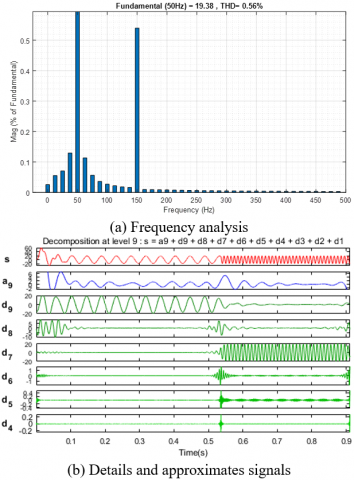
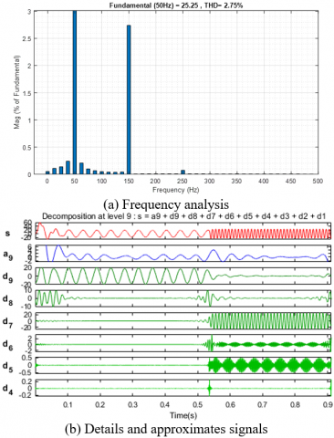
For the healthy case as illustrated in Figure 8(a), the 3rd harmonic amplitude was near zero. On the other hand, as shown in Figures 9(a), 10(a) and 11(a), when the ITSC happens, some harmonic frequencies are appeared. In these conditions, the amplitude of the 3rd and the 5th harmonic current signal in the faulty phase increased as the shorted turns number increased. Detection of harmonics multiple of three in currents waveforms of faulty phase can be used as a signature of short-circuit between turns.
Frequency analysis of the stator current in the faulty part of the phase winding shows three peaks, the first corresponds to the fundamental frequency of 50 Hz and the others 150 Hz (3rd harmonic) and 250 Hz (5th harmonic), indicating the presence of short-circuit fault as shown in Figure 10 (a) and Figure 11 (a).
Figure 8. FFT and DWT analysis in healthy state
Figure 9. FFT and wavelet analysis of current of faulty phase (as) with µ=0.5 and Rf=10Ω
Figure 10. FFT and DWT analysis of current of faulty phase (as) with µ=0.5 and Rf=1Ω
Figure 11. FFT and wavelet analysis of current of faulty phase (as) with µ=0.5 and Rf=0.1Ω
The Figures 8(b), 9(b), 10(b) and 11(b) show the wavelet analysis for the stator current in healthy and faulty states. The wavelet coefficients are calculated using the Daubechies44 mother wavelet, since the latter guarantees a correct signal decomposition, isolating the harmonic content of the fault, which gives suitable results for diagnostic purposes. Detail levels of high frequency bands provide virtually no information about the original signal. However, it is clear that the low frequency details (d5, d6 and d7) are much more relevant for fault detection because they cover the frequency band corresponding to the fundamental frequency and the frequencies due to faults. Then, the wavelet details of level 5, 6 and 7 can be easily used for ITSC detection, since the amplitude at this level increases significantly regarding the healthy case. In Figures 9b, 10b and 11b, it can be seen that the upper level signal A9 (approximation), d9 and d8 (details) do not show any significant variation. The frequency bands of the stator current wavelet decomposition are shown in Table 1. The details d5, d6 and d7 change during the presence of faults which implies that the frequencies related to faults are localized in the same frequency bands.
Table 1. Frequency bands for stator current by wavelet decomposition
|
Decomposition details |
Frequency bands (Hz) |
|
Detail at level 1(d1) |
[2500-5000] |
|
Detail at level 2(d2) |
[1250-2500] |
|
Detail at level 3(d3) |
[625-1250] |
|
Detail at level 4(d4) |
[312.5-625] |
|
Detail at level 5(d5) |
[156.25-312.5] |
|
Detail at level 6(d6) |
[78.12-156.25] |
|
Detail at level 7(d7) |
[39.06-78.12] |
|
Detail at level 8(d8) |
[19.53-39.06] |
|
Detail at level 9(d9) |
[9.76-19.53] |
In the next section, we have simulated the case of a PMSM fed by three phase PWM inverter at a frequency of 50Hz. The electromagnetic torque spectral harmonics are presented using Simulink FFT tool of “powergui” to display their frequency spectrum and their Total Harmonic Distortion (THD). Figure 12 represented the spectral analysis of electromagnetic torque for healthy motor and as shown in Figure 13a and 13b the ripples in the electromagnetic torque increase significantly when the fault resistance decreases from 10Ω to 0.1Ω.
Finally, to study the electromagnetic torque developed by the PMSM for the considered cases, a Total Harmonic Distortion (THD) is also introduced. In Table 2 the percentage values of THD is given for the stator phase current and the electromagnetic torque for both healthy and faulty PMSM under different situations.
Table 2. Current and torque THD (%) for healthy and faulty PMSM fed by PWM inverter
|
Motor state |
Faulted phase current |
Electromagnetic torque |
|
|
Healthy motor |
5.69 |
9.29 |
|
|
Faulty motor µ=0.5 |
Rf=10Ω |
5.73 |
13.11 |
|
Rf=1Ω |
6.99 |
20.12 |
|
|
Rf=0.1Ω |
18.63 |
50.18 |
|
Figure 12. Electromagnetic torque spectral analysis for healthy PMSM
Figure 13. Electromagnetic torque and its spectral analysis for faulty PMSM under full load
In this work, the PMSM model which takes into account the ITSC in the stator winding is adopted. Consequently, the model seems well suited to diagnosing and monitoring this type of fault. Two methods for the detection of ITSC fault in PMSM were presented.
The first one is based on the frequency analysis of the stator current and electromagnetic torque by FFT in the steady state condition. The detection of faults is carried out by studying the components of the sideband which have appeared around the fundamental frequency component. This conventional method is a very effective tool and widely used in stationary signal processing. Additionally, this method has important advantages such as simplicity of data acquisition systems and it has provided quite satisfactory results. However, it is impossible to estimate the time of occurrence of the fault using the FFT.
The second method based on DWT analysis can overcome these drawbacks. The results of the simulation showed the efficiency of the DWT compared to FFT, particularly in non stationary states as it provides better accuracy to identify ITSC fault. In addition, THD value can be used also as an indicator of fault detection.
The authors gratefully acknowledge the Algerian General Direction of Scientific Research and Technological Developments for providing the facilities and the financial funding of this project.
Parameters of PMSM used in simulation [9]
|
Components |
Rating values |
|
|
p Ns Pn In Rs Ls Ωs Փm J f Tn |
Number of poles Number of winding turns /slot Rated power Rated current Stator resistance/phase Stator inductance/phase Synchronous speed Magnetic flux Moment of Inertia Frictional coefficient Nominal torque |
8 40 5KW 19A 0.44Ω 2.82mH 1000rpm 0.108web 0.0006kg.m2 0.007 N.m.s/rd 10N.m |
[1] Zheng, J., Wang, Z., Wang, D., Li, Y., Li, M. (2017). Review of fault diagnosis of PMSM drive system in electric vehicles. In Proceedings of the 36th Chinese Control Conference (CCC), Dalian, China, pp. 7426-7432. https://doi.org/10.23919/ChiCC.2017. 8028529
[2] Kalimov, A., Shimansky, S. (2015). Optimal design of the synchronous motor with the permanent magnets on the rotor surface. IEEE Trans. Magnetics, 51(3): 1-4. https://doi.org/10.1109/TMAG.2014.2362961
[3] Arkan, M., Kostic-Perovic, D., Nsworth, P.J. (2005). Modeling and simulation of induction motors with inter-turn faults for diagnostics. Electric Power Systems Research, 75(1): 57-66. https://doi.org/10.1016/j.epsr.2004.08.015
[4] Fitouri, M., Bensalem, Y., Naceur, M. (2016). Modeling and detection of the short-circuit fault in PMSM using finite element analysis. IFAC-Papers Online, 49(12): 1418-1423. https://doi.org/10.1016/j.ifacol.2016.07.769
[5] Mehrjou, M.R., Mariun, N., Karami, M., Misron, N., Radzi, M.A.M. (2015). Broken rotor bar detection in LS-PMSMs based on statistical features analysis of start-up current envelope. In Proceedings of the 2015 IEEE 3rd International Conference on Smart Instrumentation, Measurement and Applications (ICSIMA), Kuala Lumpur, Malaysia. https://doi.org/10.1109/ICSIMA.2015.7559033
[6] Chen, Y., Liang, S., Li, W., Liang, H., Wang, C. (2019). Faults and diagnosis methods of permanent magnet synchronous motors: A review. Applied Sciences, 9(10): 2116. https://doi.org/10.3390/app9102116
[7] Cintron-Rivera, J.G., Foste, S.N., Strangas, E.G. (2015). Mitigation of turn-to-turn faults in fault tolerant permanent magnet synchronous motors. IEEE Transactions on Energy Conversion, 30(2): 465-475. https://doi.org/10.1109/TEC.2018.2800498
[8] Vaseghi, B., Takorabet, N., Nahid-Mobarakeh, B., Meibody-Tabar, F. (2011). Modeling and study of PM machines with inter-turn fault dynamic model–fem model. Electric Power Systems Research, 81(8): 1715-1722. https://doi.org/10.1016/j.epsr.2011.03.017
[9] Vaseghi, B., Takorabet, N., Meibody-Tabar, F. (2009). Fault analysis and parameter identification of permanent-magnet motors by the finite-element method. IEEE Transactions on Magnetics, 45(9): 3290-3295. https://doi.org/10.3390/app9102116
[10] Zafarani, M., Bostanci, E., Qi, Y., Goktas, T., Akin, B. (2018). Interturn short-circuit faults in permanent magnet synchronous machines: An extended review and comprehensive analysis. IEEE Journal of Emerging and Selected Topics in Power Electronics, 6(4): 2173-2191. https://doi.org/10.1109/JESTPE.2018.2811538
[11] Boileau, T., Leboeuf, N., Nahid-Mobarakeh, B., Meibody-Tabar, F. (2013). Synchronous demodulation of control voltages for stator inter turn fault detection in PMSM. IEEE Transactions on Power Electronics, 28(12): 5647-5654. https://doi.org/10.1109/TPEL.2013.2254132
[12] Liu, L. (2006). Robust Fault Detection and Diagnosis for Permanent Magnet Synchronous Motors. Retrieved from http://purl.flvc.org/fsu/fd/FSU_migr_etd-1186.
[13] Faiz, J., Nejadi-Koti, H., Valipour, Z. (2017). Comprehensive review on inter-turn fault indexes in permanent magnet motors. IET Electric Power Applications, 11(1): 142-156. http://dx.doi.org/10.1049/iet-epa.2016.0196
[14] Chau, F.T., Liang, Y.Z., Gao, J., Chao, X.G. (2004). Fundamentals of Wavelet Transform, Chemical Analysis. John Wiley & Sons, 316 pages. Hoboken, New Jersey, USA.
[15] Mallat, S.G. (1989). A theory for multiresolution signal decomposition: The wavelet representation. IEEE Transactions on Pattern Analysis and Machine Intelligence, 11(7): 674-693. https://doi.org/10.1109/34.192463
[16] Cusido, J., Romeral, L., Ortega, J. A., Garcia, A., Riba, J.R. (2010). Wavelet and PDD as fault detection techniques. Electric Power Systems Research, 80(8): 915-924. https://doi.org/10.1016/j.epsr.2009.12.017
[17] Vaseghi, B., Takorabet, N., Meibody-Tabar, F., Djerdir, A., Farooq, J.A., Miraoui, A. (2011). Modeling and characterizing the inter-turn short circuit fault in PMSM. In 2011 IEEE International Electric Machines & Drives Conference (IEMDC), pp. 551-556. https://doi.org/10.1109/INFO TEH. 2018.8345531
[18] Kia, S.H., Henao, H., Capolino, G.A. (2009). Diagnosis of broken-bar fault in induction machines using discrete wavelet transform without slip estimation. IEEE Transactions on Industry Applications, 45(4): 1395-1404. https://doi.org/10.1109/TIA.2009.2018975
[19] Zhang, J., Zhan, W., Ehsani, M. (2019). Fault-tolerant control of PMSM with inter-turn short-circuit fault. IEEE Transactions on Energy Conversion, 34(4): 2267-2275. https://doi.org/10.1109/TEC.2019.2936225
[20] Zhang, C., Wang, F., Wang, Z., Yang, J. (2014). Analysis of stator winding inter-turn short circuit fault of PMSM for electric vehicle based on finite element simulation. In 2014 IEEE Conference and Expo Transportation Electrification Asia-Pacific (ITEC Asia-Pacific), pp. 1-6. https://doi.org/10.1109/ITEC-AP. 2014. 6940913