Djallel Zebbar* | Souhila Zebbar | Sahraoui Kherris | Kouider Mostefa
© 2021 IIETA. This article is published by IIETA and is licensed under the CC BY 4.0 license (http://creativecommons.org/licenses/by/4.0/).
OPEN ACCESS
This paper is consecrated to the thermodynamic study and analysis of diffusion-absorption-refrigeration (DAR) plants. The mass and energy balances analysis at the evaporator has allowed to highlight a new and original parameter, which can be used to analyze DAR system performances. It is the ratio of inert gas to refrigerant vapor mass flow rates at the evaporator inlets. This coefficient, which expression has been for the first time deduced mathematically, informs about the quality of the cycle and its performance, which are deeply affected by the growth of the inert gas flow energy expended to drive the refrigerant through the evaporator. The study shows that the coefficient of performance is decreasing with the increase of the mass flow rates ratio. The latter can be also used to find the optimal operating mode for the DAR machine with a specified working fluid.
absorption, ammoniac-water-hydrogen, diffusion, evaporator, propane - n-nonane -hydrogen, refrigerant
The diffusion-absorption refrigeration machine is generally used in domestic applications often on sites which are far from electrical networks, either in the hotel sector because of its silent operation.
However, up to now in Algeria, as in all the Maghreb countries, there is no economic or industrial operator which opts for DAR systems proliferation and establishment of a manufacturing industry for such technology.
However, thousands of Maghreb households are still not connected to the national electricity network. Since the eighties, they still run DAR machines imported from Brazil, Sweden and other countries. An imported DAR refrigerator costs more than six times the price of a conventional refrigerator. Its design, which seems simple in appearance but actually very complex, has not allowed its proliferation in the Maghreb at an industrial scale. However, this machine which depends on a thermal source, whatever its origin, could have invaded Algerian homes, with the advent and the proliferation of the natural gas during the last two decades. In conjunction with solar thermal systems this refrigeration system could easily reduce the growing demand for electricity during the heat wave period.
However, several points in this machine require an in-depth examination. This is valid for the working fluids, the bubble pump, the evaporator and the exchangers. In what follows a review is exposed of the most relevant research works on DAR systems.
Perez-Garcia et al. [1] developed a model in steady state mode to predict the thermal behavior of a DAR system. The obtained results were in perfect agreement with those obtained experimentally. The authors claim that the maximum relative error in terms of COP is 8% compared with experimental results.
Chaves et al. [2] developed and validated a mathematical model for DAR simulation composed of 14 interconnected distinct parts.
Zohar et al. [3] have also developed and validated experimentally a thermodynamic model for a DAR cycle using ammonia-water-hydrogen as working fluids. They indicated that the best performance was obtained for a rich solution concentration ranging on 0.2–0.3 of ammonia mass fraction and that the recommended weak solution concentration was 0.1. They showed also that the DAR unit working with helium was more efficient than the one working with hydrogen. They concluded that this is due to the heat capacity of hydrogen which is three times lower than that of helium, which in return allows increasing the COP owing to the additional heat absorbed by the ammonia from the cooling chamber.
Jelenic et al. [4] investigated the purity of the condensate at the evaporator inlet on the performance of a DAR cycle under three configurations of sub-cooling. They found that the partial sub-cooling (PSC) configuration was the best one.
Rattner and Garimella [5] investigated DAR system with NH3/NaSCN as working fluid and He as inert gas with a distributed heated bubble-pump generator (BPG), and an enhanced absorber. They developed and validated experimentally a model as reported in their later paper [6]. Herein, they identified the evaporator and absorber as the primary limitations on DAR system performance, which requires future investigations.
Benhmidene et al. [7] show experimentally that the performance of the bubble pump was mainly dependent on the driving heat input and the submersion ratio. They determine the optimal heating power for the different submersion ratios.
Benhmidene and Chaouachi [8] carried out a theoretical study of two-phase flow instability, in bubble pump tube in order to predict pressure drop in the bubble pump. They concluded that the flow instability is essentially in the two phase zone, in which the instability is of pressure drop type. This instability decreases with increasing the tube diameter and decreasing the heat flux.
Harraz et al. [9] used the statistical associating fluid theory SAFT-γ Mie equation of state in order to model the thermodynamic functions of the three-component working fluid. They used also the computer-aided molecular design (CAMD) approach to introduce an optimization methodology. The model was validated against experimental data from an ammonia-water-hydrogen DAR prototype with good agreement (within ± 7%).
Najjran et al. [10] had conducted a detailed experimental investigation to understand the operation and to analyze the performance of a DAR unit over a range of heat-supply conditions. The thermal input was varied in the range of 150–700 W, resulting in heat source temperatures of 175–215℃ measured at the generator. The maximum COP was obtained at a generator heat input of 300 W.
Aly et al. [11] investigated experimentally a diffusion absorption refrigerator driven by the waste heat of a diesel engine exhaust gas. They indicated that by controlling exhaust gas flow, the DAR system was capable to function in a broad range of engine loads. However, they achieved 10% waste heat recovery and a maximum coefficient of performance equal to 0.10.
Wang [12] had studied the performance of the early developed by him diffusion-absorption refrigerator with solution pumps reported in [13]. The author claims that the developed DAR machine can be driven by low-temperature heat sources, in which NH3/LiNO3/He is used as working fluids and an adiabatic spray absorber with a plate-type solution cooler, is designed to enhance the mass and heat transfer, respectively. He concluded, based on the experiments and analysis, that the machine can reach the lowest Te = -13 for the corresponding refrigeration capacity and COP equal to 1.9 kW and 0.156, respectively. Moreover, he reports that lower Tc is helpful to utilize low-temperature heat source such as general solar energy water heater.
Bourseau and Bugarel [14] studied the influence of the performance of the heat exchangers, driving force and rectification parameter on the COP as a function of the generator temperature for two DAR systems. The first one use NH3-H2O-H2 as working fluids when the second use NH3-NaSCN-H2. Their study shows that the NH3-NaSCN-H2 is the best suited for the DAR machine.
Chen et al. [15] had tried to enhance the performance of DAR machine by reusing the waste heat from the rectifier to heat the weak absorbent from the absorber. For this purpose, they designed and fabricated a new generator with heat exchanger. For an unchangeable cooling capacity the new generator design demonstrated a 50% improvement in the cooling COP.
Ben Jamaa et al. [16] adopted a black-box model approach to describe the relationship between the refrigerator behavior for each heat input. They reported that a first order transfer function is an adequate model between the input and output of the machine in start-up mode.
Srikhirin and Aphornratana [17] had developed a simple mathematical model for DAR system using ammonia–water–helium working fluid. They concluded that the evaporator and absorber mass transfer performances had a strong effect on the system performances. Moreover, the system produced maximum performance when all refrigerant was completely evaporated in the evaporator. The bubble-pump is also an important part of the system. It must be designed so that the flow of refrigerant and the flow of solution are matched.
Kherris et al. [18] simulated DAR using ammonia-water mixtures and hydrogen as inert gas. They used a new mathematical model for the calculation of the thermodynamics properties of ammonia-water mixtures. A comparative analysis of the obtained results with other existing results in the literature showed good agreement.
Dardour et al. [19, 20] carried out a simulation of a heat-driven absorption-diffusion cooling machine operating with low-grade heat sources using Aspen Plus flow-sheeting program. The studied DAR used nonane as an absorbent, propane as a refrigerant and hydrogen as the inert auxiliary gas. They concluded that the C3H8/n-C9/H2 was preferable to the NH3/H2O/H2, which is a most used working fluid in commercialized cooling units.
Ben Ezzine et al. [21] studied numerically the feasibility of a solar driven DAR using the mixture R124/DMAC as working fluid and hydrogen as inert gas. They concluded that DAR system using this fluid mixture had a higher COP, required lower vapor pressures and might constitute an alternative to the conventional ammonia–water system.
In the present study, an original mathematical expression is deduced and proposed for the evaluation of the ratio of the inert gas to refrigerant vapor mass flow rates at the evaporator inlets. This original ratio is then used to compare performances of several DAR systems from the literature. It can be also used to find the optimal operating mode for the DAR machine with a specified working fluid.
The schematic diagram of an absorption-diffusion refrigeration system evaporator is shown in Figure 1. It includes two inlets 1 and 2 for the inert gas and the refrigerant respectively and an outlet 3 for the gas mixture.
Figure 1. Schematic representation of a diffusion-absorption machine evaporator
To evaluate the performance of the DAR machine, the coefficient of performance is often used, which is the ratio of the cooling power and the thermal power transmitted to the rich solution at the bubble pump. The latter can be evaluated according to different temperatures in well-defined points of the machine, to circulation ratio f, to concentration rates of the rich and lean solutions and also according to the ammonia concentration rate in the gas mixture.
In this study, a new expression is proposed for the evaluation of the ratio of inert gas to refrigerant vapor mass flow rates at the evaporator inlets used afterwards for the evaluation of the DAR system performances. The mentioned flow rates ratio is deduced from the energy balance in the evaporator expressed as follows:
$\dot{m}_{1}\left(h_{1}+\frac{v_{1}^{2}}{2}\right)+\dot{m}_{2}\left(h_{2}+\frac{v_{2}^{2}}{2}\right)+\dot{Q}_{e v}=\dot{m}_{3}\left(h_{3}+\frac{v_{3}^{2}}{2}\right)$ (1)
Neglecting flows kinetic energy, Eq. (1) becomes:
$\dot{m}_{1} h_{1}+\dot{m}_{2} h_{2}+\dot{Q}_{e v}=\dot{m}_{3} h_{3}$ (2)
where:
$\dot{m}_{1}+\dot{m}_{2}=\dot{m}_{3}$ (3)
Let’s write:
$\frac{\dot{Q}_{e v}}{\dot{m}_{1}}=h_{f g}$ and $\frac{\dot{m}_{2}}{\dot{m}_{1}}=r$ (4)
We can found:
$\frac{\dot{m}_{3}}{\dot{m}_{1}}=\frac{\dot{m}_{1}+\dot{m}_{2}}{\dot{m}_{1}}=1+r$ or $\frac{\dot{m}_{1}}{\dot{m}_{3}}=\frac{1}{1+r}$ (5)
$\frac{\dot{m}_{2}}{\dot{m}_{3}}=\frac{\dot{m}_{2}}{\dot{m}_{1}+\dot{m}_{2}}=\frac{1}{1+\frac{\dot{m}_{1}}{\dot{m}_{2}}}=\frac{1}{1+\frac{1}{r}}=\frac{r}{1+r}$ (6)
Taking into account expressions (3)-( 6), Eq. (2) becomes:
$h_{R}\left(T_{1}\right)+r h_{i}\left(T_{2}\right)+h_{f g}=(1+r) h_{3}$
$=(1+r)\left[\frac{\dot{m}_{2}}{\dot{m}_{3}} h_{i}\left(T_{3}\right)+\frac{\dot{m}_{1}}{\dot{m}_{3}} h_{R}\left(T_{3}\right)\right]$
$=(1+r)\left[\frac{r}{1+r} h_{i}\left(T_{3}\right)+\frac{1}{1+r} h_{R}\left(T_{3}\right)\right]$
$h_{R}\left(T_{1}\right)+r h_{i}\left(T_{2}\right)+h_{f g}=r h_{i}\left(T_{3}\right)+h_{R}\left(T_{3}\right)$
$r=\frac{h_{f g}-\left[h_{R}\left(T_{3}\right)-h_{R}\left(T_{1}\right)\right]}{\left(h_{i}\left(T_{3}\right)-h_{i}\left(T_{2}\right)\right)}$ (7)
where: $h_{1}=h_{R}\left(T_{1}\right), h_{2}=h_{i}\left(T_{2}\right)$ and $h_{3}=h_{\text {gac mixture }}\left(T_{3}\right)$ are the enthalpies of the refrigerant, the inert gas and the gas mixture at the evaporator inlets (1 and 2) and outlet 3 respectively. They are depending on the temperature.
The expression of r (Eq. (7)) can be further simplified as follows:
$r=\frac{h_{f \mathrm{~g}}-\left[C_{P R}\left(T_{3}\right) T_{3}-C_{P R}\left(T_{1}\right) T_{1}\right]}{\left(C_{P i}\left(T_{3}\right) T_{3}-C_{P i}\left(T_{2}\right) T_{2}\right)}$ (8)
where, $C_{p R}(T)$ and $C_{p i}(T)$ are the isobaric thermal heat of the refrigerant and the inert gas respectively. They are temperature depending.
2.1 Applications
This relationship (7) was estimated for DAR systems with different working fluids. The first and second DAR systems are chosen from [3] and [2]. They used ammonia / water as working fluid and hydrogen as inert gas. The third one was examined by Dardour in [20]. It used the propane / n-nonane as working fluid and hydrogen as inert gas. The fourth DAR system was studied by Ratther et al. [6] and used the ammonia / sodium thiocyanate as working fluid and helium as inert gas.
The last DAR system is studied by Ben Ezzin et al. [21] and used a R124/ DMAC as working fluid and hydrogen as inert gas.
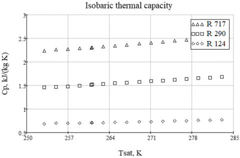
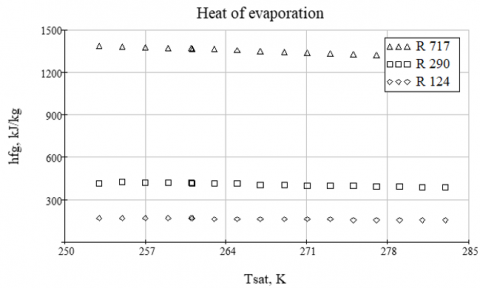
The isobaric thermal capacities and heat of evaporation for the R717, R290 and R124 are used from Ashrae [22] and are represented in Figures 2 and 3 respectively.
Figure 2. Variation of isobaric specific heat capacity for different working fluid
Figure 3. Variation of the evaporation heat for different working fluid
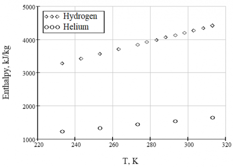
Figure 4. The inert gas enthalpy variation
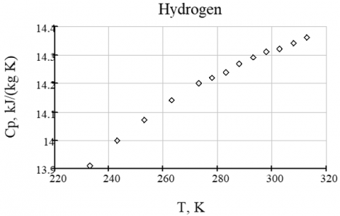
The inert gas (H2 and He) enthalpies are also used from Ashrae [22] and are represented in Figure 4. The hydrogen isobaric thermal capacity is showed on Figure 5. That of helium is taken equal to 5.193 kJ/(kg. K), for a temperature ranging from -40 to 40℃.
Figure 5. Hydrogen isobaric specific heat capacity variation
The isobaric thermal capacities of the refrigerant $C_{p R}$ and the inert gas $C_{p i}$ can also be calculated from the following expression reported in [23]:
$C_{P}(T)=\frac{1}{M}\left(a+b T+c T^{2}+d T^{3}\right)$ (9)
where: a, b and c are coefficients reported for the different gases in [23]. M is the molecular mass of the refrigerant and the inert gas.
It is important to note that temperatures at the evaporator inlets are those reached at the first contact of the refrigerant and the inert gas. That is to say temperatures after the expansion phase in the mixer considered to be an adiabatic evolution.
The calculated ratio of inert gas to refrigerant vapor mass flow rates at the evaporator inlets for several absorption-diffusion refrigeration systems with the main parameters necessary for their evaluations are reported in the Table 1.
For the DAR system using C3H8/ n-C9H20 /H2 the calculated mass flow rates ratio is equal to 2.5. It corresponds to a first contact temperature reached equal to -6℃ as reported by Dardour [20]. The same author has demonstrated that the first contact temperature of the system is a function of the mass flow rates ratio. For low ratios the temperature decreases. The latter reaches the value of 2℃ for a mass flow rates ratio r equal to 0.25 then it decreases to reach a minimum of -8℃ for a mass flow rates ratio equal to 7.45. The author claims that the temperature increases gradually for higher flow rates and reaches approximately 2° for a mass flow rates ratio r around 34.
In case of the DAR system with NH3-NaSCN-He the mass flow rates ratio can be calculated from the values of mass flow rates reported by Rattner et al. [5, 6]. Indeed, Rattner et al. [6] estimate that the refrigerant $\dot{m}_{R}$ and inert gas $\dot{m}_{i}$ mass flow rates range respectively from 2.5-4.2 g /min and 25-41 g /min, which gives a mass flow rates ratio around 10, which is close to the value calculated from Eq. 8 and displayed in Table 1.
For the DAR system with NH3 / H2O / H2 the mass flow rates ratio is around 6-7, which situates the DAR system using NH3/H2O/H2 in the middle. Meanwhile, the DAR system using NH3/NaSCN/He is the least efficient. This can be explained by the fact that this mixture was initially chosen by Rattner et al. [6] as an alternate working fluid mixture suitable for operation at reduced source temperatures i.e. low exergy source.
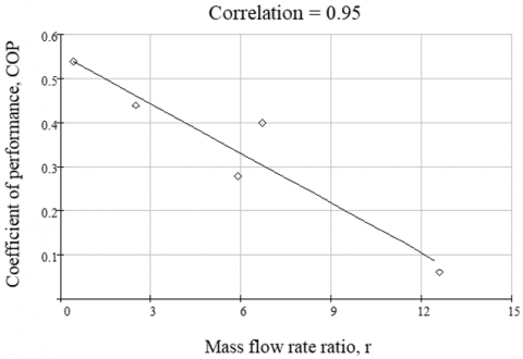
It appears form Figure 6 that the coefficient of performance is decreasing with the increase of the mass flow rates ratio r. This shows that in DAR system with height flow rates ration r, the performances are deteriorated. This can be explained by the growth of the inert gas flow energy expended to drive the refrigerant through the evaporator.
Unlike the previous DAR system, the ones using C3H8/ n-C9H20 /H2 and R124-DMAC-H2 as working mixture have shown highest performances in conjunction of low flow rates ratio. This explains once more the previous assumptions about the work expended to drive the refrigerant through the evaporator.
Furthermore, the accurate value of this coefficient can be determined by numerical simulation of flows inside the evaporator. The simulation must take into account the presence in the evaporator of the refrigerant in both vapor and liquid states.
Figure 6. Variation of the COP according to the mass flow rates ratio
Table 1. Mass flow rates ratio estimation
|
Working mixture |
Pt, (bar) |
PR_IN_ev (bar) |
PR_OUT_ev (bar) |
T1 (°C) |
T2 (°C) |
T3 (°C) |
r |
COP |
|
NH3/H2O /H2 [03] |
25 |
1 |
3 |
-33 |
5 |
-10 |
5.9 |
0.28 |
|
NH3/H2O /H2 [02] |
18 |
3.5 |
6.4 |
-4.2 |
23.4 |
11.2 |
6.7 |
0.4 |
|
C3H8/ n-C9H20 /H2 [20] |
11.9 |
3.42 |
5 |
-6 |
12 |
2 |
2.5 |
0.44 |
|
NH3-NaSCN-He [6] |
11.5 |
3-4.27 |
4.8 |
-8 |
25 |
6.8 |
12.6 |
0.06 |
|
R124-DMAC-H2 [21] |
5.65 |
0.91 |
1.96 |
-14.5 |
27 |
5 |
0.44 |
0.54 |
The ratio of inert gas to refrigerant vapor mass flow rates at the evaporator inlets has been deduced. This coefficient has been evaluated for several experimental DAR systems found in the literature. It was demonstrated that this mass flow rates ratio is strongly linked to the DAR performances and can be used to determine the best working fluids and the optimal operating mode.
We conclude that the DAR system using C3H8/ n-C9H20 /H2 and R124-DMAC-H2 as working mixture reaches the highest performance due to their lowest mass flow rates ratio.
In perspective, a numerical simulation of flows inside the evaporator must be done. It will, certainly highlight the relationship of the deduced coefficient with other parameters such as the geometry of the evaporator, DAR power and many other parameters.
This work is supported by the Directorate-General for Scientific Research and Technological Development (DGRSDT), Algeria.
|
BPG |
Bubble-Pump Generator |
|
COP |
Coefficient of performance |
|
CP |
Specific heat at constant pressure, kJ/(kg K) |
|
C3H8/ n-C9H20 |
Propane/n-nonane |
|
DAR |
Diffusion-absorption refrigeration |
|
DMAC |
N, N’-dimethylacetamide (absorbent) |
|
h |
Enthalpy kJ /kg |
|
H2 |
Hydrogen |
|
He |
Helium |
|
hfg |
Evaporation heat of the refrigerant, (kJ/kg) |
|
NH3/LiNO3 |
Ammonia / lithium nitrate |
|
$\dot{m}_{1}, \dot{m}_{2}$ and $\dot{m}_{3}$ |
Mass flow rate of the refrigerant, the inert gas and the mixture at the evaporator respectively, (kg/s) |
|
NH3/ H2O |
Ammonia/water |
|
NH3/ NaSCN |
Ammonia / sodium thiocyanate |
|
pSC |
Partial sub-cooling |
|
$\dot{Q}_{e v}$ |
Cooling capacity or power of the DAR, W. |
|
R |
Thermal resistance (K W-1) |
|
R 124 |
2-chloro-l,l,l,2,-tetrafluoroethane (refrigerant) |
|
R 290 |
Propane |
|
R 717 |
Ammonia |
|
T |
Temperature (°C) |
|
v |
Velocity (m/s) |
|
Subscripts |
|
|
c |
condenser |
|
ev |
evaporator |
|
i |
inert gas |
|
R |
refrigerant |
|
sat |
saturation |
|
1and 2 |
evaporator inlet |
|
3 |
evaporator outlet |
[1] Perez-Garcia, V., Rodriguez-Munoz, J.L., Belman-Flores, J.M., Rubio-Maya, C., Ramirez-Minguela, J.J. (2019). Theoretical modeling and experimental validation of a small capacity diffusion-absorption refrigerator. International Journal of Refrigeration, 104: 302-310. https://doi.org/10.1016/j.ijrefrig.2019.05.014
[2] Chaves, F.D., Moreira, M.F.S., Koury, R.N., Machado, L., Cortez, M.F.B. (2019). Experimental study and modelling within validation of a diffusion absorption refrigerator. International Journal of Refrigeration, 101: 136-147. https://doi.org/10.1016/j.ijrefrig.2019.01.019
[3] Zohar, A., Jelinek, M., Levy, A., Borde, I. (2005). Numerical investigation of a diffusion absorption refrigeration cycle. International Journal of Refrigeration, 28(4): 515-525. https://doi.org/10.1016/j.ijrefrig.2004.11.003
[4] Jelinek, M., Levy, A., Borde, I. (2016). The influence of the evaporator inlet conditions on the performance of a diffusion absorption refrigeration cycle. Applied Thermal Engineering, 99: 979-987. https://doi.org/10.1016/j.applthermaleng.2016.01.152
[5] Rattner, A.S., Garimella, S. (2016). Low-source-temperature diffusion absorption refrigeration. Part I: Modeling and cycle analysis. International Journal of Refrigeration, 65: 287-311. https://doi.org/10.1016/j.ijrefrig.2015.10.010
[6] Rattner, A.S., Garimella, S. (2016). Low-source-temperature diffusion absorption refrigeration: Part II: Experiments and model assessment. International Journal of Refrigeration, 65: 312-329. https://doi.org/10.1016/j.ijrefrig.2015.11.016
[7] Benhmidene, A., Hidouri, K., Chaouachi, B., Gabsi, S., Bourouis, M. (2016). Experimental investigation on the flow behaviour in a bubble pump of diffusion absorption refrigeration systems. Case Studies in Thermal Engineering, 8: 1-9. https://doi.org/10.1016/j.csite.2016.04.002
[8] Benhmidene, A., Chaouachi, B. (2019). Investigation of pressure drop in the bubble pump of absorption-diffusion cycles. Applied Thermal Engineering, 161: 114-101. https://doi.org/10.1016/j.applthermaleng.2019.114101
[9] Harraz, A.A., Freemanm, J., Wang, K., Markides, C.N. (2019). Diffusion-absorption refrigeration cycle simulations in gPROMS using SAFT-γ Mie, ICAE2018. Energy Procedia, 158: 2360-2365. https://doi.org/10.1016/j.egypro.2019.01.284
[10] Najjaran, A., Freeman, J., Ramos, A., Markides, C.N. (2019). Experimental investigation of an ammonia-water-hydrogen diffusion absorption refrigerator. Applied Energy, 256: 113899. https://doi.org/10.1016/j.apenergy.2019.113899
[11] Aly, W.I., Abdo, M., Bedair, G., Hassaneen, A.E. (2016). Thermal performance of a diffusion absorption refrigeration system driven by waste heat from diesel engine exhaust gases. Applied Thermal Engineering, 114: 621-630. http://dx.doi.org/10.1016/j.applthermaleng.2016.12.019
[12] Wang, H. (2012). A new style solar-driven diffusion absorption refrigerator and its operating characteristics. Energy Procedia, 18: 681-692. https://doi.org/10.1016/j.egypro.2012.05.083
[13] Wang, H. (2011). Experimental study on LiNO3-NH3 diffusion-absorption refrigeration system. Key Engineering Materials, 474-476: 2335-2340. https://doi.org/10.4028/www.scientific.net/KEM.474-476.2335
[14] Bourseau, P., Bugarel, R. (1986). Absorption-diffusion machines: Comparison of the performances of NH3-H2O and NH3-NaSCN. International Journal of Refrigeration, 9(14): 206-214. https://doi.org/10.1016/0140-7007(86)90092-7
[15] Chen, J., Kim, K.J., Herold, K.E. (1996). Performance enhancement of a diffusion-absorption refrigerator. International Journal of Refrigeration, 19(3): 208-218. https://doi.org/10.1016/0140-7007(96)87215-X
[16] Ben Jemaa, R., Mansouri, R., Bellagi, A. (2016). Dynamic testing and modeling of a diffusion absorption refrigeration system. International Journal of Refrigeration, 67: 249-258. http://dx.doi.org/10.1016/j.ijrefrig.2016.03.008
[17] Srikhirin, P., Aphornratana, S. (2002). Investigation of a diffusion absorption refrigerator. Applied Thermal Engineering, 22(11): 1181-1193. https://doi.org/10.1016/S1359-4311(02)00049-2
[18] Kherris, S., Zebbar, D., Makhlouf, M., Zebbar, S., Mostefa, K. (2012). Étude et analyse d’une machine frigorifique à absorption-diffusion solaire NH3-H2O-H2. Revue des Energies Renouvelables, 15(3): 373-382.
[19] Dardour, H., Cézac, P., Reneaume, J.M., Bourouis, M., Bellagi, A. (2013). Numerical investigation of an absorption-diffusion cooling machine using C3H8/C9H20 as binary working fluid. Oil & Gas Science and Technology–Revue d’IFP Energies Nouvelles, 68(2): 249-254. https://doi.org/10.2516/ogst/2012086
[20] Dardour, H. (2012). Étude des machines frigorifiques à absorption-diffusion utilisant un mélange d’alcanes: étude systématique et modélisation rigoureuse de l’absorbeur, thèse de doctorat, Monastir.
[21] Ben Ezzine, N., Garma, R., Bellagi, A. (2010). A numerical investigation of a diffusion-absorption refrigeration cycle based on R124-DMAC mixture for solar cooling. Energy, 35(5): 1874-1883. https://doi.org/10.1016/j.energy.2009.12.032
[22] Lemmon, E.W., McLinden, M.O., Penoncello, S.G. (2001). Thermophysical properties of refrigerants (chapter 20). In: ASHRAE Handbook Fundamentals: 20.1-20.65.
[23] Cengel, Y.A., Boles, M.A. (2015). Thermodynamics: An Engineering Approach, Appendix 1. Property Tables and Charts (SI UNITS), Eighth edition, McGraw-Hill Education.