Jitendra Mohan Giri* | Pawan Kumar Singh Nain
© 2020 IIETA. This article is published by IIETA and is licensed under the CC BY 4.0 license (http://creativecommons.org/licenses/by/4.0/).
OPEN ACCESS
Thermoelectric coolers (TECs) use the Peltier effect for thermal management of electronic devices. They offer high reliability and low noise operation but limited in use due to low performance. In the present work, through the use of a genetic algorithm (GA), two single-objective optimizations associated with two separate objectives are carried out, aiming maximization of cooling capacity and maximization of the coefficient of performance (COP) of TEC with space restrictions. Interfacial thermal resistance and electrical contact resistance are taken into consideration to obtain a more realistic model. This paper presents a new approach to finding appropriate solutions by optimally arranging the length of n-type and p-type thermoelectric (TE) elements, the cross-sectional area of TE elements, and input electric current. To validate the GA predictions, three-dimensional steady-state TEC models are prepared, and finite-element simulations are carried out using ANSYS®. Close agreement between the GA and ANSYS® has been observed. This study provides a new mathematical optimization model that is more realistic and is quite close to the physical construction of TEC modules manufactured by industry.
thermoelectric cooler, optimization, genetic algorithm, finite-element method, ANSYS workbench, cooling capacity, COP
The solid-state thermoelectric (TE) technology attract great attention of the researchers because of its potential use as green energy conversion devices. The Peltier effect of thermoelectric technology offers direct conversion of electrical energy into temperature difference. Conversely, the Seebeck effect of TE technology provides the conversion of thermal energy of temperature differential into electric power [1]. A thermoelectric cooler (TEC) dissipates the heat and removes the hotspots of the electronic devices in an environment-friendly manner using the Peltier effect. A TEC could be installed easily within a restricted space due to its practical manufacturing possibility in small sizes. Thermoelectric coolers must be appropriately designed and manufactured to meet the necessary performance requirements. Two essential performance parameters of a TEC are the cooling capacity and the coefficient of performance. The cooling capacity of thermoelectric coolers ranges from milliwatts to watts depending on the requirements. The maximum cooling effect or higher COP for a thermoelectric cooler can be achieved through upgraded TE materials and improved device design.
The efficiency of TE materials increases with a material property known as figure of merit (Z). The term Z is defined as α2/RK, where α is the Seebeck coefficient, R is the electrical resistance, K is the thermal conductance. With absolute temperature (T), the dimensionless figure of merit (ZT) is used to characterize TE materials. A higher value of ZT corresponds to better cooling performance. Hicks et al. described that the value of ZT could be enhanced by reducing the dimensions of thermoelectric materials [2, 3]. At room temperature, Venkatasubramanian et al. [4] reported a ZT∼2.4 for p-type Bi2Te3/Sb2Te3 superlattice devices. Peak ZT values of different TE materials are attainable at different temperatures. Over the past two decades, significant progress in maximizing ZT has been made in developing thermoelectric materials [5-10].
With the significant ongoing efforts to improve TE materials, the researchers also focus on designing and assembling the TECs. The investigations established that the geometric structure of thermoelectric elements affects the performance of thermoelectric coolers [11-15]. Huang et al. [16] combined a three dimensional TEC model with a simplified conjugate-gradient technique. They reported that at a fixed temperature difference and fixed current, a substantial value of the total area of TE elements with small element length can maximize cooling capacity. Yang et al. [17] reported that micro-thermoelectric coolers operating in a transient regime could provide a better cooling effect. Nain et al. [18] reported that a suitable value of dimensionless current can enhance the performance of TEC. Pareto-optimal solutions were obtained for different settings of temperature ratio. Shen et al. [19] reported that a two-segmented TE element structure can reduce the joule heating effect from 50% to 35% on the cold side. The results showed a remarkable 118.1% improvement in maximum cooling capacity. Nain et al. [20] optimized cooling capacity and COP performance of TEC using dimensional structural parameters as design variables. The geometrical parameters were optimized to find Pareto-optimal solutions. Jeong [21] reported that the COP of TEC can be increased by optimal values of current and length of thermoelements. Lee [22] proposed a dimensional analysis approach to find out the optimal design of TE devices with feasible mechanical constraints. Mijangos et al. [23] reported a novel design of asymmetrical legs to enhance the performance of TE devices.
Literature reports several studies on performance optimization of TEC [13, 15, 24-29]. However, in the current study, the two performance parameters, namely, cooling capacity and coefficient of performance, are optimized as two single-objective optimization problems. So far, the standard approach has been to choose either a set of geometric design variables or operating design variables. In this paper, a combined set of three design variables, electric current, length of n-type and p-type TE elements and cross-sectional area of TE elements is chosen in both optimization problems. The optimization algorithm mathematical model is customized to handle the presence of ceramic substrate, copper contacts, electric contact resistances at the interface, and heat sink, which are essential parts in the fabrication of a TEC module in industrial applications. It is a new aspect of modelling TEC. The geometry of the thermoelectric element plays a vital role in the performance of the thermoelectric cooler. However, tight geometric space constraints are found in many telecommunications and other scientific applications. The TEC is used for cooling electronic devices where space restrictions are quite prevalent. Hence, consideration of performance optimization of TEC with space restrictions is a very valid assumption. The genetic algorithm is used to maximize the cooling capacity and COP of a TEC with space restrictions in two different optimization problems. The optimization results are validated through finite-element simulations using ANSYS®.
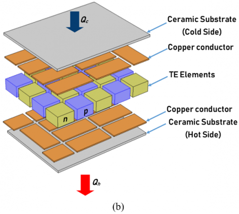
The general schematic diagram of a practical single-stage thermoelectric cooler is shown in Figure 1 (a). A thermoelectric cooler (TEC) consists of many thermoelectric (TE) elements. These thermoelectric elements are assembled electrically in series. Copper tabs are used to interconnect n-type and p-type elements. This array configuration is sandwiched between two thermally conducting ceramic substrates. Figure 1 (b) is an exploded view diagram of a practical TEC system.
The basic unit of the physical model of a TEC is a thermocouple (pair of n-type and p-type semiconductor thermoelectric elements). The number of pairs of thermoelectric elements may vary from several to hundreds. On the one hand, the manufacturing cost of TEC is high, and on the other hand, many TE materials are high-priced. Further, to predict the performance of a TEC with a heat sink, knowing the temperature at important points is quite difficult. Also, the thermal resistances in the heat sink, copper conductors, and ceramic substrates play a significant role in the total resistance to heat flow in the TEC system. These issues make the performance optimization problem challenging to solve. In this work, the effects of electrical contact resistance and thermal resistance are included. The impact of Joule heat and thermal conduction are included as well.
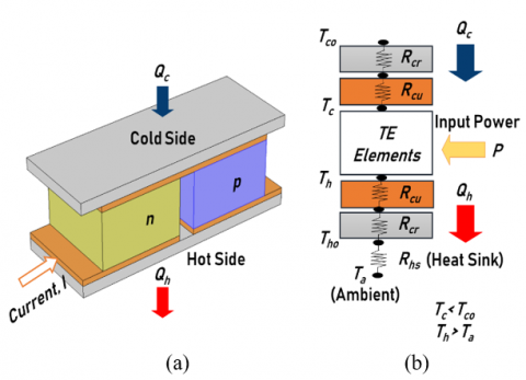
In this work, to simplify the investigation considering thermal resistances, a thermal-resistance model has been developed. This model includes thermal resistance of copper tabs, ceramic substrates, and cold side heat sink for developing a more realistic TEC model. A thermocouple and the developed thermal resistance model for this work is shown in Figure 2.
Figure 1. (a) Single-stage TEC (b) Exploded view of TEC
Figure 2. (a) Thermoelectric couple (b) Thermal resistance model
By applying the electrical analogy of the heat flow to the thermal resistance model shown in Figure 2(b), the temperatures at the TEC hot surface and the cold surface can be expressed as
$T_{h}=Q_{h}\left(R_{h s}+R_{c r}+R_{c u}\right)+T_{a}$ (1)
$T_{c}=T_{c o}-Q_{c}\left(R_{c r}+R_{c u}\right)$ (2)
where, Th and Tc are the hot and cold side temperatures (K) of n-type and p-type elements. Qh is the heat rejection rate (W) from the hot side. Qc is the heat absorption rate at the cold side (W), which is referred to as the cooling capacity in common usage. Tco and Tho are the temperatures (K) at the cold surface and hot surface of TEC, respectively. Rhs is the thermal resistance (℃/W) of the heat sink attached to the hot side of TEC, Rcr is the thermal resistance (℃/W) of the ceramic substrates, and Rcu is the thermal resistance (℃/W) of the copper tabs. Ta is the ambient temperature (K).
In the current study, some reasonable assumptions are considered.
A constant electric current pass through the circuit of dissimilar semiconductors. The heat is pumped to one of the two sides. It results in making one side cool and another side hot. A heat sink attached externally to the hot side ceramic substrate dissipates heat to the ambient environment. A thermoelectric couple produces cooling or heating effect depending on the direction of the electric current. Eq. (3) and Eq. (4) shows the heat energy balance at the cold and the hot side of the thermoelectric cooler. Tc and Th correspond to the temperature at TE element-copper conductor interface at the cold side and hot side, respectively, and used with the same reference in each referred equation of this paper.
$Q_{c}=2 N\left[I \alpha T_{c}-\frac{k A\left(T_{h}-T_{c}\right)}{L}-\frac{1}{2} I^{2}\left(\frac{\rho L}{A}+2 \frac{r_{c}}{A}\right)\right]$ (3)
$Q_{h}=2 N\left[I \alpha T_{h}-\frac{k A\left(T_{h}-T_{c}\right)}{L}+\frac{1}{2} I^{2}\left(\frac{\rho L}{A}+2 \frac{r_{c}}{A}\right)\right]$ (4)
where, thermoelectric material properties α, ρ, k are the Seebeck coefficient (V/K), electrical resistivity (Ωm) and thermal conductivity (W/mK), respectively. rc is the electrical contact resistance (Ωm2). L and A are the length (m) and cross-sectional area (m2) of n-type and p-type thermoelectric elements, respectively. I is the supplied electric current (A), and N is the total number of thermoelectric couples. There are three essential terms on the right side of Eq. (3) and Eq. (4). The first terms, IαTc and IαTh, represent the Peltier heat at the cold junction and hot junction, respectively. The second heat transfer term kA (Th −Tc)/L is due to thermal conduction. The third term ½ I2 (ρL/A+2rc/A) represents the Joule heat generation.
The selection of thermoelectric materials directly affects the performance of TEC. The material properties of thermoelectric elements are temperature dependent. Bismuth telluride (Bi2Te3) is the popular thermoelectric material used in thermoelectric coolers. The material properties of Bi2Te3 used in this work are given below, as specified by Fraisse et al. [30]. Tave is the average of Tc and Th.
$\alpha=\left(22224+930.6 T_{\text {ave }}-0.9905 T_{\text {ave }}^{2}\right) \times 10^{-9}$ (5)
$\rho=\left(5112+163.4 T_{\text {ave }}+0.6279 T_{\text {ave }}^{2}\right) \times 10^{-10}$ (6)
$k=\left(62605-277.7 T_{\text {ave }}+0.4131 T_{\text {ave }}^{2}\right) \times 10^{-4}$ (7)
Cooling capacity (Qc) is one of the significant performance indexes of TEC, which is used in this study. The Coefficient of Performance (COP) is another crucial performance index of thermoelectric coolers. Both performance indexes are considered in the current study. COP is the ratio of cooling capacity to power consumption and defined by the following equation.
Coefficient of Performance, $\mathrm{COP}=\frac{Q_{c}}{P}$ (8)
The input electric power (P), as shown in Figure 2(b), can be calculated by the following relationship.
Input Electric Power $, P=Q_{h}-Q_{c}$ (9)
The cost-competitive and high-performance TEC system will pave the way for a promising future of such green devices.
The various geometrical, material and operational parameters affect the cooling performance of the thermoelectric cooler. Besides, the restricted maximum area of cooling devices, which depends on its application in electronic devices, is a significant constraint for TEC design. Performance optimization is vital to enhance the use of thermoelectric coolers in real-world applications. In this study, the objective is to maximize the cooling capacity of TEC with space restrictions. This paper presents a new approach by selecting electric current, length of n-type and p-type TE elements and cross-sectional area of TE elements as design variables.
3.1 Optimization of cooling capacity of TEC
The single-objective optimization problem for maximization of the cooling capacity of TEC is formulated mathematically as:
$\left\{\begin{array}{ll} & \text {Maximize } Q_{c} \\ \text {Subjectto} & \\ I_{\min } \leq I \leq I_{\max } \\ L_{\min } \leq L \leq L_{\max } \\ A_{\min } \leq A \leq A_{\max }\end{array}\right.$ (10)
Further, the total number of thermoelectric couples (N) is a dependent design variable. Its value depends on the cross-sectional area of n-type and p-type thermoelectric elements and computed using Eq. (11).
$N=\frac{\text {Available area}(S) \text { of } T E C \times \text { packaging density}}{2 \times A}$ (11)
The optimization problem, as mentioned in Eq. (10) has been solved using some specific values of parameters. Table 1 lists the values of the parameters and properties used in this work.
Table 1. Values of parameters and properties
|
Description |
Parameter |
Value |
|
Cold surface temperature Ambient temperature Heat sink thermal resistance Electrical contact resistance Available C.S. area of TEC Packaging density Ceramic thermal conductivity Copper thermal conductivity |
Tco Ta Rhs rc S PD kcr kcu |
293.15 K or 20℃ 298.15 K or 25℃ 0.10 ℃ /W 1 x 10⁻⁸ Ω m2 15 mm x 15 mm 80% 35.3 W/m°C 386 W/m-°C |
Genetic algorithm (GA) is an evolutionary algorithm based on natural genetics. The genetic algorithm begins with the creation of a population of possible solutions (called individuals). Based on the value of the objective function, each member of the population is assigned a fitness value. To evolve better solutions, new generations are created by undergoing selection, recombination, and mutation of solutions. The fitness of the new generation is evaluated. This cycle is repeated over generations until the stopping criterion is met. The objective of GA is to search for an appropriate solution for the design problems. This involves maximization or minimization of the objective function.
Genetic algorithm is a population-based optimization approach to find optimal or near-optimal solutions. In terms of quality and robustness of solutions, GA's capability has been widely recognized for providing excellent results on classic discrete and continuous optimization problems. The genetic algorithm's performance depends on many genetic parameters such as population size, crossover, and mutation rate. GA parameters play an important role, and a different combination of parameters may lead to a significant GA performance change. The smaller population size helps faster convergence than larger population sizes. The decision on various GA parameters and operators are usually selected based on recommendations made by GA researchers.
The real-variable GA employing SBX operator created by Deb and Agarwal is used in this study [31]. Table 2 lists the values of the GA parameters like population size, crossover, mutation & number of generations that are used in the present study. The results are reported after multiple runs of GA converged to the same best solution.
Table 2. Values of GA parameters
|
Parameter |
Value |
|
Population size Crossover probability Mutation probability Number of generations |
50 0.80 0.25 1000 |
3.2 Optimization of Coefficient of Performance (COP) of TEC
The objective of the second optimization problem is the maximization of the coefficient of performance of TEC. The design variables are the same as those selected in the previous problem. The fixed values of the parameters and properties are identical to the values used in the previous problem and described in Table 1. The thicknesses of ceramic substrates and copper tabs have the same values of 0.2 mm and 0.1 mm, respectively. This new problem is mathematically expressed as:
$\left\{\begin{array}{l}\text { Maximize COP } \\ \text { Subjectto } \\ \qquad \begin{array}{l}I_{\min } \leq I \leq I_{\max } \\ L_{\min } \leq L \leq L_{\max } \\ A_{\min } \leq A \leq A_{\max }\end{array}\end{array}\right.$ (12)
The goal of this optimization problem is to find the design variables within the variable bounds that result in the maximum COP of the device.
3.3 Optimization procedure
To apply the genetic algorithm to the optimization problems described in Eq. (10) and Eq. (12), the fitness evaluation of solution vectors is required. However, the procedure for evaluating fitness function is slightly tricky for this problem. The unknown values of Th and Tc are initially guessed for approximately estimate Qc and Qh. The initial guess for Th and Tc satisfies TEC's prevailing temperature conditions, i.e., Th >Ta and Tc <Tco. In principle, these conditions must be satisfied. The initial guess will be iteratively modified and reach the exact value. Eq. (1) and Eq. (2) are used to calculate new values of Th and Tc that are termed as Thn and Tcn. These are updated repeatedly to corresponding new values until the difference in old values and new values are negligible. Then the values of Qc and Qh are accepted.
A flowchart for GA implementation for these two optimization problems are given in Figure 3.
The brief steps of the fitness evaluation procedure for a population individual (solution vector) followed in this work are described below.
Figure 3. Flowchart for GA implementation
In the first segment of present work, cooling capacity Qc, the first performance index of TEC is maximized. The algorithm of this study is coded in C language. The GA source code is developed by Deb and used in this work [32]. Multiple runs of 1000 generations have been repeated, and the best run is reported in Table 3 on which algorithm converged several times during various runs.
Table 3. Result of GA based optimization for maximum Qc
|
Optimized |
Optimal Values of Design Variables |
|||
|
Qc |
I |
L |
A |
N |
|
|
|
|
|
(Dependent) |
|
8.476807 W |
2.993 A |
1.0 mm |
1.607 mm2 |
56 |
At optimal values of design variables, the corresponding values of Th and Tc are found at 28.59℃ and 19.78℃, respectively. The hot surface temperature (Tho) of TEC is 27.84℃. The heat rejection rate (Qh) at the hot side is 28.401 W. For the maximized Qc, the value of COP obtained is 0.425. It can be observed that L is hitting lower bound while other parameters have optimal values without hitting any bound of the permitted range.
To optimize the second performance index of TEC, the coefficient of performance (COP) is maximized. The boundary conditions and assumptions are similar to those considered during the optimization of Qc. This optimization problem is solved using the same parameters of GA, as mentioned in Table 2. The steps to implement GA in this problem are similar to those used in the optimization of cooling capacity and shown with the help of a flowchart in Figure 3. Several runs of 1000 generations have been performed to reach solutions with the highest quality, and the best run is reported in Table 4. It is worth mentioning that GA converged to the same results in various runs.
Table 4. Result of GA optimization for maximum COP
|
Optimized |
Optimal Values of Design Variables |
|||
|
COP |
I |
L |
A |
N |
|
|
|
|
|
(Dependent) |
|
4.11 |
0.283A |
2.0mm |
1.956mm2 |
45 |
With this maximum COP, the corresponding Qc is obtained as 0.745992 W. The corresponding values of Th and Tc are 25.11℃ and 19.97℃, respectively. The hot surface temperature (Tho) of the thermoelectric cooler is 25.09℃. The heat rejection rate (Qh) at the hot side is 0.927 W. The optimal values of I and A design variables are unique, while the optimal value of L is hitting the upper boundary. It can be seen that COP increased significantly, and cooling capacity is just 8.8% of Max. Qc obtained, as mentioned in Table 4. It is found that a design variable L hits its lower bound for high Qc while for high COP, L hits its upper bound.
From these two results, it is well established that maximization of Qc and maximization of COP are obtained at a different set of design parameters. Also, maximum Qc does not ensure providing optimal COP and vice-versa. This means that these objectives are conflicting. The resolution of these conflicting design objectives will be Pareto solutions through multi-objective optimization if there is no specific objective interest. It will be useful to determine a set of solutions that will allow the decision-maker to choose among them according to the application's requirement.
The results of this study show that it is possible to improve the cooling capacity or COP of the thermoelectric coolers with these design variables to be competitive with compressor-based cooling devices. The complex impacts of electrical contact resistance and thermal resistance deteriorate the TEC performance. These factors always need to be included in the model for optimization and analysis.
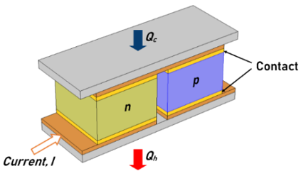
Finite-element simulation is a computational method for solving complex engineering problems of the real-world. The finite element simulations are performed to validate the optimization results of GA. ANSYS® is a useful, common-purpose finite-element method tool. It is used to solve a broad range of engineering problems numerically. Hence ANSYS® is used in the current study. The Thermal-electric module of ANSYS® is capable of providing simultaneous solutions of thermal and electrical fields. The present work makes use of the thermal-electric module for the steady-state analysis of the TEC model. A three-dimensional non-linear finite-element model is setup. The model in this work is set up with one pair of n-type and p-type elements as per the GA result. A new approach to incorporate the effect of electric contact resistance on the performance of TEC is used in the present study. The finite-element simulation includes four additional geometric parts termed as ‘Contact’ and used for modelling of the electric contact resistance effect. These parts have material properties as per the thermo-electric behaviour of electrical contact resistance. The contact geometries are created at each end of the TE elements. The complete schematic of the TEC model for Finite-element simulation to validate GA results is shown in Figure 4.
Figure 4. Schematic of TEC for finite-element simulation to validate GA results
5.1 Finite-element simulation for maximum Qc
To validate GA predictions for maximum Qc, the length of n-type and p-type elements is taken as 1.0 mm, as reported in Table 3. The TE elements are of the square cross-section of 1.27 mm. The distance between n-type and p-type elements is 0.31 mm. The material properties for the simulation are computed at average (Tave) of Th and Tc values obtained during the GA based optimization of Qc. The finite-element simulation input parameters of the modelled TEC are given in Table 5.
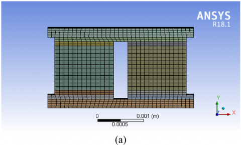
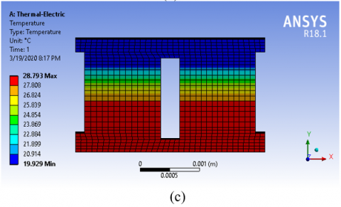
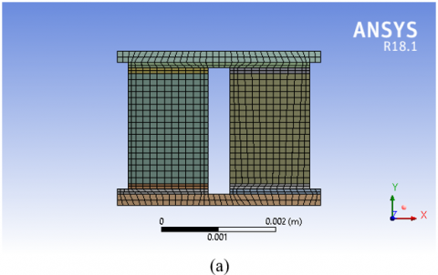
To model adiabatic heat transfer from the exposed surfaces of TEC, a small convection loss of 0.000001 W/mK was applied on all surfaces except the ones on which boundary conditions mentioned in Table 5 are specified. The computationally generated mesh, electric voltage, and temperature distribution across the finite-element model of the thermoelectric cooler are shown in Figure 5.
Table 5. Finite-element simulation input parameters for maximum Qc
|
Description |
Parameter |
Value per pair of TE Elements |
|
Cooling Capacity Current Temperature (hot side of TEC) |
Qc I Tho |
0.1514 W 2.993 A 27.84℃ |
Figure 5. (a) Mesh (b) Voltage distribution (c) Temperature distribution in the finite-element model for maximum QC
The parameters obtained from finite-element simulation are compared with the GA results and reported in Table 6. It is observed that the results for a single pair of TE elements from GA simulation and those obtained from finite-element simulation are in close agreement. The finite-element simulation result represents a 3-D solution based on a numerical technique, while GA results are based on 1-D analytical equations. Hence, the optimization result obtained by GA is verified through the solutions of the thermal-electric module of ANSYS®.
Table 6. Comparison of results for maximum Qc
|
Parameter |
GA |
ANSYS® |
Remarks |
|
Tco Qh P |
20℃ 0.507 W 0.356 W |
20.25℃ 0.508 W 0.357 W |
Value per pair of TE elements |
In this segment, the finite-element simulation for maximum COP is performed with ANSYS® software. The steady-state TEC model consists of TE elements with 2.0 mm length, as reported in Table 4. The TE elements are of the square cross-section of 1.4 mm. The distance between n-type and p-type elements is 0.38 mm. The temperature-dependent material properties are calculated based on the average of Th, and Tc found during GA based optimization of COP. The input parameters of the TEC model for finite-element simulation are given in Table 7.
Table 7. Finite-element simulation input parameters for maximum COP
|
Description |
Parameter |
Value per pair of TE Elements |
|
Cooling Capacity Current Temperature (hot side of TEC) |
Qc I Tho |
0.0165 W 0.283 A 25.09℃ |
The three-dimensional steady-state TEC model is created, and predictions of GA based optimization are tested for maximum COP. For this simulation, the mesh, electric voltage, and temperature distribution are shown in Figure 6. The finite-element simulation results agree well with the GA results. The parameters for GA and finite-element simulation results have been compared and reported in Table 8.
Figure 6. (a) Mesh (b) Voltage distribution (c) Temperature distribution in the finite-element model for maximum COP
The ANSYS® result is consistent with GA based optimization results for the maximization of COP. Hence, the optimization result is verified through the solutions of the thermal-electric module of ANSYS®.
Table 8. Comparison of results for maximum COP
|
Parameter |
GA |
ANSYS® |
Remarks |
|
Tco Qh P |
20℃ 0.021 W 0.004 W |
19.61℃ 0.021 W 0.004 W |
Value per pair of TE elements |
This paper presents an effective method with a new analytical model to improve cooling capacity and coefficient of performance of thermoelectric cooler for a specific need. In order to analyze more than one factor simultaneously, the thermoelectric cooler's current and geometric parameters were set to be variables. The described study emphasized to find out the optimal values of current, length of n-type and p-type TE elements and cross-sectional area of TE elements within size restrictions on space. It was found that length, the cross-sectional area of thermoelectric elements, and input electric current had a great influence on the TEC performance. Performance optimizations to maximize cooling capacity and to maximize COP were successfully performed by the genetic algorithm. The use of this stochastic optimization algorithm based on natural genetics theory proved to be the right option. The genetic algorithm successfully converged to the same optimal results over several runs. The finite-element simulations through ANSYS® validated the GA result.
The work suggests that these design variables should be appropriately selected in practical application. Results revealed that the relationship between the coefficient of performance and cooling capacity is inverse. The maximum cooling capacity does not provide optimum COP and vice-versa. The smaller length of thermoelectric elements facilitates maximum cooling capacity whereas greater length of elements obtains maximum coefficient of performance. The best performance requires specific values of electric current and cross-sectional area of TE elements as per the objective requirements. The appropriate optimum results can be achieved for any space restriction. This study can guide the TEC designers working for some specific cooling targets. The use of microprocessor-based control of input power parameters to get an optimal cooling with the best possible COP under dynamic conditions needs to be explored.
|
A COP I k L N P PD Qc Qh Rhs Rcr Rcu S |
cross-sectional area of TE elements, m2 coefficient of performance electric current, A thermal conductivity, W/m K length of thermoelectric element, m number of thermoelectric couples power input, W packaging density heat absorption rate at the cold side, W heat rejection rate from the hot side, W thermal resistance of heat sink, ℃/W thermal resistance of ceramic, ℃/W thermal resistance of copper, ℃/W available cross-sectional area of TEC, m2 |
|
Tc Th Tco Tho Ta Tave Z |
temperature at the cold side of elements, K temperature at the hot side of elements, K temperature at the cold surface of TEC, K temperature at the hot surface of TEC, K ambient temperature, K average of Tc and Th, K figure of merit, 1/K |
|
Greek symbols |
|
|
a ρ |
Seebeck coefficient, V/K electrical resistivity, Ω m |
[1] Rowe, D.M. (1995). CRC Handbook of Thermoelectrics. CRC Press. https://doi.org/10.1201/9781420049718
[2] Hicks, L.D., Dresselhaus, M.S. (1993). Effect of quantum-well structures on the thermoelectric figure of merit. Physical Review B, 47: 12727. https://doi.org/10.1103/PhysRevB.47.12727
[3] Hicks, L.D., Dresselhaus, M.S. (1993). Thermoelectric figure of merit of a one-dimensional conductor. Physical Review B, 47: 16631. https://doi.org/10.1103/PhysRevB.47.16631
[4] Venkatasubramanian, R., Siivola, E., Colpitts, T., O’Quinn, B. (2001). Thin-film thermoelectric devices with high room-temperature figures of merit. Nature, 413: 597-602. https://doi.org/10.1038/35098012
[5] Su, C.H. (2019). Design, growth and characterization of PbTe-based thermoelectric materials. Progress in Crystal Growth and Characterization of Materials, 65(2): 47-94. https://doi.org/10.1016/j.pcrysgrow.2019.04.001
[6] Tan, G., Zhao, L.D., Kanatzidis, M.G. (2016). Rationally designing high-performance bulk thermoelectric materials. Chemical Reviews, 116(19): 12123-12149. https://doi.org/10.1021/acs.chemrev.6b00255
[7] Poudel, B., Hao, Q., Ma, Y., Lan, Y., Minnich, A., Yu, B., Yan, X., Wang, D.Z., Muto, A. (2008). High-thermoelectric performance of nanostructured bismuth antimony telluride bulk alloys. Science, 320(5876): 634-8. https://doi.org/10.1126/science.1156446
[8] Chen, G., Dresselhaus, M.S., Dresselhaus, G., Fleurial, J.P., Caillat, T. (2003). Recent developments in thermoelectric materials. International Materials Reviews, 48(1): 45-66. https://doi.org/10.1179/095066003225010182
[9] Sootsman, J.R., Chung, D.Y., Kanatzidis, M.G. (2009). New and old concepts in thermoelectric materials. Angewandte Chemie - International Edition, 48(46): 8616-8639. https://doi.org/10.1002/anie.200900598
[10] Alam, H., Ramakrishna, S. (2013). A review on the enhancement of figure of merit from bulk to nano-thermoelectric materials. Nano Energy, 2(2): 190-212. https://doi.org/10.1016/j.nanoen.2012.10.005
[11] Völklein, F., Min, G., Rowe, D.M. (1999). Modelling of a microelectromechanical thermoelectric cooler. Sensors and Actuators, A: Physical, 75(2): 95-101. https://doi.org/10.1016/S0924-4247(99)00002-3
[12] Yu, J., Wang, B. (2009). Enhancing the maximum coefficient of performance of thermoelectric cooling modules using internally cascaded thermoelectric couples. International Journal of Refrigeration, 32(1): 32-39. https://doi.org/10.1016/j.ijrefrig.2008.08.006
[13] Abramzon, B. (2007). Numerical optimization of the thermoelectric cooling devices. Journal of Electronic Packaging, 129(3): 339-347. https://doi.org/10.1115/1.2753959
[14] Pan, Y., Lin, B., Chen, J. (2007). Performance analysis and parametric optimal design of an irreversible multi-couple thermoelectric refrigerator under various operating conditions. Applied Energy, 84(9): 882-892. https://doi.org/10.1016/j.apenergy.2007.02.008
[15] Cheng, Y.H., Lin, W.K. (2005). Geometric optimization of thermoelectric coolers in a confined volume using genetic algorithms. Applied Thermal Engineering, 25(17-18): 2983-2997. https://doi.org/10.1016/j.applthermaleng.2005.03.007
[16] Huang, Y.X., Wang, X.D., Cheng, C.H., Lin, D.T.W. (2013). Geometry optimization of thermoelectric coolers using simplified conjugate-gradient method. Energy, 59: 689-697. https://doi.org/10.1016/j.energy.2013.06.069
[17] Yang, R., Chen, G., Kumar, A.R., Snyder, G.J., Fleurial, J.P. (2005). Transient cooling of thermoelectric coolers and its applications for microdevices. Energy Conversion and Management, 46(9-10): 1407-1421. https://doi.org/10.1016/j.enconman.2004.07.004
[18] Nain, P.K.S., Sharma, S., Giri, J.M. (2010). Non-dimensional multi-objective performance optimization of single stage thermoelectric cooler. Lecture Notes in Computer Science, 404-413. https://doi.org/10.1007/978-3-642-17298-4_44
[19] Shen, L., Zhang, W., Liu, G., Tu, Z., Lu, Q., Chen, H., Huang, J.Q. (2020). Performance enhancement investigation of thermoelectric cooler with segmented configuration. Applied Thermal Engineering, 168: 114852. http://doi.org/10.1016/j.applthermaleng.2019.114852
[20] Nain, P.K.S., Giri, J.M., Sharma, S., Deb, K. (2010). Multi-objective performance optimization of thermo-electric coolers using dimensional structural parameters. Lecture Notes in Computer Science, pp. 607-614. https://doi.org/10.1007/978-3-642-17563-3_71
[21] Jeong, E.S. (2014). A new approach to optimize thermoelectric cooling modules. Cryogenics, 59: 38-43. https://doi.org/10.1016/j.cryogenics.2013.12.003
[22] Lee, H.S. (2013). Optimal design of thermoelectric devices with dimensional analysis. Applied Energy, 106: 79-88. https://doi.org/10.1016/j.apenergy.2013.01.052
[23] Fabián-Mijangos, A., Min, G., Alvarez-Quintana, J. (2017). Enhanced performance thermoelectric module having asymmetrical legs. Energy Conversion and Management, 148: 1372-1381. https://doi.org/10.1016/j.enconman.2017.06.087
[24] Göktun, S. (1996). Optimal performance of a thermoelectric refrigerator. Energy Sources, 18(5): 531-536. https://doi.org/10.1080/00908319608908788
[25] Cheng, Y.H., Shih, C. (2005). Application of genetic algorithm to maximizing the cooling capacity in a thermoelectric cooling system. Proceedings of the IEEE International Conference on Industrial Technology, Hong Kong, China. https://doi.org/10.1109/ICIT.2005.1600648
[26] Thiébaut, E., Goupil, C., Pesty, F., D’Angelo, Y., Guegan, G., Lecoeur, P. (2017). Maximization of the thermoelectric cooling of a graded Peltier device by analytical heat-equation resolution. Physical Review Applied, 8(6). http://doi.org/10.1103/PhysRevApplied.8.064003
[27] Seifert, W., Pluschke, V. (2014). Maximum cooling power of a graded thermoelectric cooler. Physica Status Solidi (B) Basic Research, 251(7): 1416-1425. https://doi.org/10.1002/pssb.201451038
[28] Erturun, U., Erermis, K., Mossi, K. (2014). Effect of various leg geometries on thermo-mechanical and power generation performance of thermoelectric devices. Applied Thermal Engineering, 73(1): 128-141. https://doi.org/10.1016/j.applthermaleng.2014.07.027
[29] Chen, L., Li, J., Sun, F., Wu, C. (2007). Optimum allocation of heat transfer surface area for heating load and COP optimisation of a thermoelectric heat pump. International Journal of Ambient Energy, 28(4): 189-196. https://doi.org/10.1080/01430750.2007.9675043
[30] Fraisse, G., Ramousse, J., Sgorlon, D., Goupil, C. (2013). Comparison of different modeling approaches for thermoelectric elements. Energy Conversion and Management, 65: 351-356. https://doi.org/10.1016/j.enconman.2012.08.022
[31] Deb, K., Agrawal, R.B. (1994). Simulated binary crossover for continuous search space. Complex Systems, 9(2).
[32] Deb, K. (2001). Single-objective GA code in C. https://www.iitk.ac.in/kangal.