Habib Benbouhenni* | Zinelaabidine Boudjema | Abdelkader Belaidi
© 2020 IIETA. This article is published by IIETA and is licensed under the CC BY 4.0 license (http://creativecommons.org/licenses/by/4.0/).
OPEN ACCESS
This work presents a power control for a doubly-fed induction generator (DFIG) using in the wind energy conversion system (WECS) connected to the grid. The proposed control strategy employs two control schemes, a traditional direct power control (DPC) and neural DPC (NDPC) with neural pulse width modulation (NPWM) technique to directly calculate the required rotor control voltage to eliminate the instantaneous errors of active and reactive powers. In this work the advantages of conventional DPC and NDPC-NPWM method are presented, the performance and robustness of these two strategies are compared between them. First, we present a model of wind turbine and DFIG machine, then a synthesis of the strategies and their application in the DFIG power control. Simulation results on a 1.5MW grid-connected DFIG system are provided by MATLAB/SIMULINK.
DFIG, DPC, WECS, NDPC, NPWM, NDPC-NPWM
Currently, variable speed wind power generation systems (WPGS) are continuously increasing their market shared, since they are capable of tracking the wind speed variations by adapting the shaft speed, and thus, achieving the optimal power generation. The mostly used WPGS is based on doubly fed induction generator (DFIG), which rotor connects through back-to-back converters, and stator is connected to the grid directly [1]. The major advantage of these facilities lies in the fact that the power rate of the inverters is around 25-30% of the nominal generator power [2].
The traditional control technique for DFIG-based wind turbine (DFIG-WT) is vector control in which d-q components of rotor currents are directly linked with stator reactive/active power or flux/torque and thus the current components can be used to control the stator reactive and active power, respectively, by transforming all variables into a reference frame fixed to voltage vector or stator flux vector [3]. Regarding this method, an accurate synchronization with the stator flux vector enables a decoupled control of the injection of the stator active power (Ps) and reactive power (Qs), via the q-axis and the d-axis component of the rotor’s currents. Also, to the decoupling control of the stator Qs and Ps, the synchronously rotating reference frame transforms enables the vector control to treat the stator variables of the machine as DC signals. This feature has resulted in its implementation in most DFIG-WT, through the tuning of the controller parameters is not an easy job. Another drawback of the vector control is several transformations involved, as well as the heavenly dependence with the stator flux position measurement or estimation. Moreover, this technique also requires the accurate value of machine parameters such as resistances, and inductances and nonlinear operation of the DFIG is not considered for tuning current controllers [4]. Then the performance of the vector control technique is affected by changing machine parameters and operation conditions. DFIG control mechanisms are reported using the stator flux oriented (SFO) frame with the position of the stator flux space (SFS) estimated through the measurement of the SFS vector in the α-β reference frame [5]. Indirect vector control (IVC) based on fuzzy space vector pulse width modulation (FSVPWM) has been proposed [6]. An SFO DFIG control strategy is proposed, in with the position of the SFS vector is estimated through the measurements of stator voltage and rotor current space vector in the α-β reference frame [7]. Direct vector control (DVC) with FSVPWM is proposed to regulate the Ps and Qs of DFIG-WT [8]. An SFO strategy of a cascaded DFIG is proposed, in which one of the main approaches used to estimate the position of stator flux space vector is to add a delay angle of 90° to the stator voltage space vector [9]. IVC control based on the five-level neural SVPWM technique has been proposed [10]. The author studied a comparison between IVC control and DVC control. To know which one is better than the other [11]. The DVC strategy is proposed, in with the rotor converter is controlled by the three-level neural SVPWM technique [12]. The four-level FSVPWM technique is designed to minimize the power ripple and harmonic distortion of the DFIG controlled by the DVC strategy [13]. The author using three-level NSVPWM to improve IVC control of DFIG-WT [14]. Fuzzy pulse width modulation (FPWM) is proposed to reduce the harmonic distortion of stator current [15]. The FPWM technique is better than the NSVPWM strategy [16]. DVC control based on the four-level NSVPWM technique has been proposed [17]. The Ps and Qs ripples of the DFIG controlled by DVC with a seven-level SVPWM technique were reduced [18]. Other technique approaches are also proposed recently, such as direct power control (DPC) techniques using the SFO frame [19]. DPC strategy is similar to direct torque control (DTC) in principle. In the DPC method, two hysteresis comparators, namely Ps and Qs comparators are selected to determine the inverter instantaneous switching state. In this strategy, the instantaneous switching state of the rotor side converter is determined based on the Ps and Qs errors. This strategy is detailed [20-22]. On the other hand, this strategy gives more harmonic distortion of rotor/stator current and power ripples. Several techniques have been proposed to improve or overcome these deficiencies in the DPC strategy. Twelve sectors DPC control scheme was designed to control the DFIG by using artificial neural networks (ANNs) [23]. Five-level DPC method based on the ANN algorithm (5L-DPC-ANN) is proposed to minimize the power ripple of DFIG-WT [24]. However, the 5L-DPC-ANN control scheme gives a good dynamic response compared to classical DPC. A neural sliding mode control (NSMC) was proposed based on neural pulse width modulation (NPWM) [25]. The rotor flux and electromagnetic torque ripples of DFIG-WT controlled by DTC strategy based on fuzzy super-twisting sliding mode (FSTSM) algorithm were reduced [26]. Reactive and active powers proportional-integral (PI) regulators and seven-level SVPWM technique were combined to replace the traditional switching table and hysteresis comparators [27]. Fuzzy logic controller (FLC) and the SMC method are combined to minimize the harmonic distortion of the rotor current for DFIG-WT [28]. Second-order sliding mode controller (SOSMC) based on the ANN algorithm has been proposed [29]. A DPC strategy based on the neural super-twisting sliding mode (NSTSM) algorithm has been proposed [30]. Reactive and active powers PI regulators and three-level NSVPWM techniques were combined to replace the switching table and classical hysteresis comparators [31]. The DPC strategy based adaptive-network-based fuzzy inference system (ANFIS) of three-phase PWM rectifier have been proposed [32]. The DPC strategy based on neural hysteresis comparators has been proposed [33]. The maximum power point tracking (MPPT) based on the fuzzy logic controller (FLC) is presented [34]. The DPC method based fuzzy logic of three-phase PWM rectifier has been proposed [35]. A modified DPC strategy was proposed based on the backstepping method of the grid [36]. I have concluded from all these proposed strategies to control the DFIG-WT that there is no good technique up to the time and every technique has disadvantages and advantages.
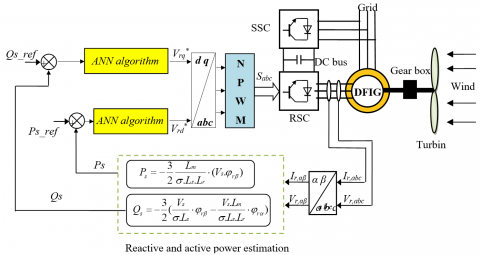
The original contribution is the application of the ANN algorithm and neural PWM (NPWM) technique in the DPC method with three-phase DFIG-WT and simulation investigation of this novel method. In this work, the DPC method with the application of the ANN algorithm and two-level NPWM technique has been considered. The main advantages of the neural DPC control with two-level NPWM technique (NDPC-NPWM) are the simplicity to implement and the minimized ripples of electromagnetic torque, reactive and active powers compared to classical DPC and vector control techniques.
This work is divided into seven sections. In section 1, the introduction is presented. In section 2, the mathematical model of the wind turbine based on the ANFIS-MPPT algorithm is described. The classical DPC method with the switching table has been discussed in section 3. In section 4, the description of the two-level NPWM (2L-NPWM) strategy is presented. Section 5 deals with the description of the neural DPC method with the application of the 2L-NPWM strategy. Simulation studies are presented and discussed in section 6. The work is concluded with a summary.
The mechanical power of the wind turbine is a function of the available power in the wind.
The mechanical power of the wind turbine can be obtained based on (1) [27, 29]:
$\mathop{P}_{w}=\mathop{P}_{v}.\mathop{C}_{p}(\lambda ,\beta )$ (1)
$\mathop{P}_{v}=\frac{\rho \pi \mathop{R}^{2}\mathop{V}_{w}^{3}}{2}$ (2)
where, Vw is the wind speed, ρ is the air density and R is the blade length, Cp is the aerodynamic coefficient of power, β is the blade pitch angle in a pitch-controlled wind turbine, respectively.
The mechanical torque of the wind turbine can be obtained as follow:
$\mathop{T}_{w}=\frac{\mathop{P}_{w}}{\mathop{\Omega }_{t}}=\frac{\mathop{C}_{p}(\lambda ,\beta ).\rho \pi \mathop{R}^{2}\mathop{V}_{w}^{3}}{2\mathop{\Omega }_{t}}$ (3)
where, Cp is a nonlinear function of λ and has a unique maximum value for λ=λopt
The tip speed ratio [25]:
$\lambda =\frac{\mathop{w}_{t}.\mathop{R}_{t}}{\mathop{V}_{w}}$ (4)
where, wt is the angular speed of the wind turbine, Rt is the angular speed of the wind turbine, λ is the tip speed ratio.
The Eq. (5) represents the mathematical equation of Cp. On the other hand, this mathematical equation is detailed in ref. [29]. The aerodynamic coefficient of power is related to the blade pitch angle, the tip speed ration, and the constant values (C1, C2, C3, C4, C5 and C6).
$Cp(\beta ,\lambda )=C1.(\frac{C2}{\lambda i}-C3.\beta -C4).\exp (\frac{-C5}{\lambda i})+C6.\lambda $ (5)
where, C1=0.5176, C2=116, C3=0.4, C4=5, C5=21, C6=0.0068 [24, 29].
$\frac{1}{\lambda i}=\frac{1}{\lambda +0.08.\beta }-\frac{0.035}{^{^{\mathop{\beta }^{3}+1}}}$ (6)
Clearly, the turbine speed has to be changed along with wind speed so that optimal tip speed ration is maintained for maximum power capture and the generator active power matches up to output power of the turbine.
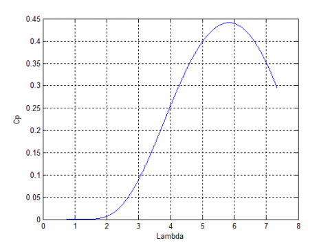
Figure 1 shows the curve of the power coefficient versus λ for a constant value of the patch angle β. It is clear from this figure that the Cp is a nonlinear function. Also, there is a value of λ for which Cp is maximized. On the other hand, this curve is characterized by the optimum point (λopt=5.8, Cpmax= 0.44, and β=0) this value is called the Betz limit, which is the point corresponding to the maximum power coefficient Cp and therefore the most of the mechanical power recovered.
Figure 1. Wind turbine generator Cp-λ characteristics
To extract the maximum power generated, we must maintain λ at the optimal control rotor speed λopt, the measurement of wind speed is difficult, an estimate of its value can be obtained by:
$\mathop{V}_{w}=\frac{\mathop{w}_{t}.\mathop{R}_{t}}{\mathop{\lambda }_{opt}}$ (7)
where, λopt is the optimal tip speed ratio.
The electromagnetic power must be set to the following value:
$\mathop{P}_{ref}=\frac{\pi .\rho }{2}\mathop{C}_{p\max }.\mathop{\mathop{R}_{t}}^{2}\mathop{V}_{w}^{3}$ (8)
where, Pref is the mechanical power of the wind turbine, Cpmax is the maximum value of the Cp.
For the electromagnetic power reference value, it is easy to determine the value of the electromagnetic torque setting:
$\mathop{T}_{ref}=\frac{\mathop{P}_{ref}}{\mathop{w}_{t}}$ (9)
where, wt is the angular speed of the wind turbine, Trefis the torque of wind turbine.
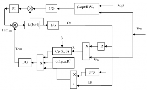
Figure 2. Wind turbine control
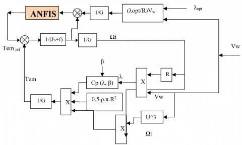
The wind turbine control is shown in Figure 2. The MPPT based on the Kalman filter algorithm, where the PI controller of MPPT was replaced by a kalman filter [37]. The MPPT technique based on fuzzy logic has been proposed [38]. MPPT and neural controller are combined to control the wind turbine [39]. A new particle swarm optimization (PSO) based MPPT control of a wind-driven self-excited induction generator for the pumping system is presented [40]. In this section, the MPPT technique was proposed based on the ANFIS algorithm, where the proposed MPPT technique is simple. On the other hand, the PI controller of the traditional MPPT technique is replaced by the ANFIS controller. Besides, the proposed MPPT technique minimized the tip speed ration and coefficient power compared to the classical MPPT technique and proposed MPPT [29, 38]. The proposed MPPT technique is shown in Figure 3.
Figure 3. MPPT with ANFIS algorithm
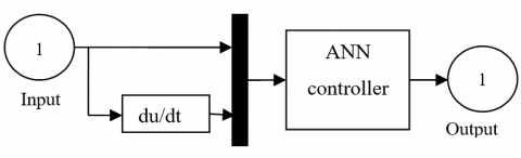
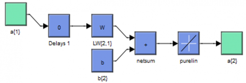
Figure 4. ANFIS controller
The block diagram of the ANFIS controller is shown in Figure 4. ANFIS architecture was first proposed by Jang [41] in 1993. This method is a technique based on observations and engineering experience. This method has the advantage of simplicity and easy implementation. However, the ANFIS algorithm is a widely applied artificial intelligence that combines the advantages of both fuzzy logic and ANN algorithm it is generally used for complex systems in various fields [42, 43]. The ANFIS rules for the proposed system are given in Table 1. On the other hand, the ANN method is widely used in the control of AC machine. However, this method is robust and simple strategy compared to another intelligent technique (fuzzy logic, genetic algorithm and ANFIS method).
In intelligent techniques, there are many types of neural networks. More existing types widely used a feedforward neural network (FNN), radial basis function neural network (RBFNN), modular neural network (MNN), Kohonen self organizing neural network (KSONN), recurrent neural network (RNN), and conventional neural network (CNN). In this paper, we use the FNN method because is a simple and robust technique. The FNN algorithm was the first type of neural network algorithm. This intelligent method is similar to the CNN algorithm, where the neurons have learnable weights and biases. Its application has been in control and electrical engineering. In this intelligent method, the mathematical model of the system is not necessary. This method is based on observation and experimentation. There are several algorithms to training neural networks, the most famous of which are recalled: Gradient descent w/momentum & adaptive lr backpropagation, Gradient descent with adaptive lr backpropagation, Gradient descent with momentum, and Levenberg-Marquardt backpropagation.
Table 1. ANFIS ruls
|
e |
NB |
NM |
NS |
EZ |
PS |
PM |
PB |
|
∆e |
|||||||
|
NB |
NB |
NB |
NB |
NB |
NM |
NS |
EZ |
|
NM |
NB |
NB |
NB |
NM |
NS |
EZ |
PS |
|
NS |
NB |
NB |
NM |
NS |
EZ |
PS |
PM |
|
EZ |
NB |
NM |
NS |
EZ |
PS |
PM |
PB |
|
PS |
NM |
NS |
EZ |
PS |
PM |
PB |
PB |
|
PM |
NS |
EZ |
PS |
PM |
PB |
PB |
PB |
|
PB |
EZ |
PS |
PM |
PB |
PB |
PB |
PB |
Table 2. Parameters of the ALRB algorithm
|
Parameters of the ALR |
Values |
|
Training |
Gradient Descent with momentum & Adaptive LR (traingdx) |
|
TrainParam.Lr |
0.05 |
|
TrainParam.goal |
0 |
|
Performances |
Mean Squard Error (mse) |
|
TrainParam.mu |
0.8 |
|
TrainParam.eposh |
300 |
|
TrainParam.show |
50 |
|
derivative |
Default (default deriv) |
|
Number of hidden layer |
1 |
|
Number of layer 1 |
1 |
|
Number of layer 2 |
1 |
|
Number of neurons in hidden layer |
5 |
|
Number of neurons in layer 2 |
1 |
|
Number of neurons in layer 1 |
2 |
|
Coeff of acceleration of convergence (mc) |
0.9 |
|
Functions of activation |
Tensing, Purling, traingdx |
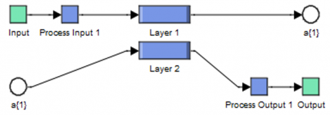
Figure 5. Block diagram of ANN controller
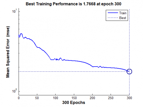
Figure 6. Training performance
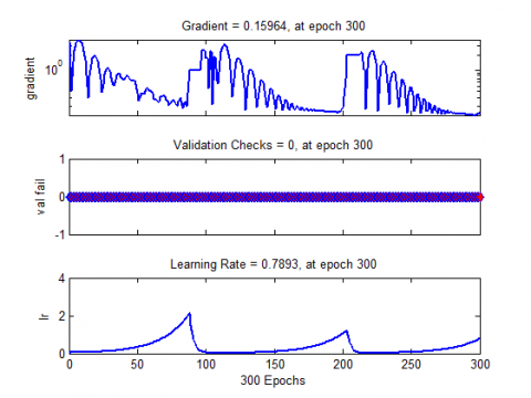
Figure 7. ALR characteristics
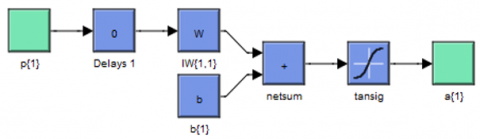
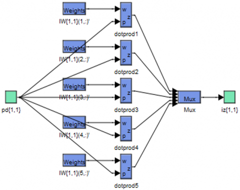
Figure 8. Block diagram of layer 1
Figure 9. Block diagram of layer 2
Figure 10. Block diagram of hidden layer
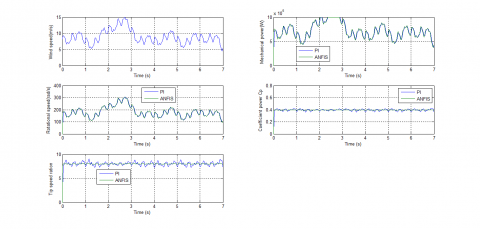
Figure 11. Wind speed
Figure 12. Mechanical power
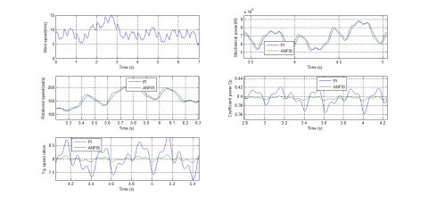
Figures 11-17 show the obtained simulation results. We can see that the mechanical power and rotational speed of the DFIG are proportional to the variation of wind speed. The coefficient power is given by Figure 14, is maintained constant at its value 0.4. Figure 15 shows the waveforms of tip speed ration. The wind tip speed ration is also kept at 8. On the other hand, the MPPT with the ANFIS controller minimizes the ripples presents in coefficient power and tip speed ration compared to the traditional MPPT technique.
Figure 13. Rotational speed
Figure 14. Coefficient power Cp
Figure 15. Tip speed ration
Figure 16. Zoom in the coefficient power
Figure 17. Zoom in the tip speed ration
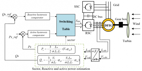
Traditionally, DPC control is a similar to the DTC method, where, many advantages: simplicity in the calculation, fast dynamic response, and robustness against machine parameter mismatches. Figure 18 shows the classical DPC of the DFIG using the switching table. The classical switching table is shown in Table 3. Also, the DPC method imposes some drawbacks such as power ripples and variable switching frequencies. Although several techniques have been proposed to minimize the power ripple and fixed switching frequency. So the DPC strategy based on SVPWM and ANN algorithm has been proposed [44]. This proposed technique provides advantages such as minimized harmonic distortion of stator current of DFIG, robustness against change in the machine parameters. The DPC method based on fuzzy logic is proposed [45]. However, this technique restricts its command on fixed power gained from the turbine. Besides, it does not consider the turbine dynamics connected to the DFIG and its analytical information. The DPC method is presented based on fuzzy logic and genetic algorithm (GA), and an FL-GA algorithm is used to minimize the stator reactive and active power error in reference tracking [46].
Table 3. Switching table of DPC method
|
N |
1 |
2 |
3 |
4 |
5 |
6 |
|
|
Hq |
Hp |
||||||
|
0 |
1 |
6 |
1 |
2 |
3 |
4 |
5 |
|
0 |
0 |
7 |
0 |
7 |
0 |
7 |
|
|
-1 |
2 |
3 |
4 |
5 |
6 |
1 |
|
|
1 |
1 |
5 |
6 |
1 |
2 |
3 |
4 |
|
0 |
7 |
0 |
7 |
0 |
7 |
0 |
|
|
-1 |
3 |
4 |
5 |
6 |
1 |
2 |
|
The magnitude of rotor flux, which can be estimated by:
$\left\{ \begin{matrix} \mathop{\varphi }_{r\alpha }=\int\limits_{0}^{t}{(\mathop{v}_{r\alpha }}-\mathop{R}_{r}\mathop{i}_{r\alpha })dt \\ \mathop{\varphi }_{r\beta }=\int\limits_{0}^{t}{(\mathop{v}_{r\beta }}-\mathop{R}_{r}\mathop{i}_{r\beta })dt \\\end{matrix} \right.$ (10)
The rotor flux amplitude is given by:
$\mathop{\varphi }_{r}=\sqrt{\mathop{\varphi }_{r\alpha }^{2}+\mathop{\varphi }_{r\beta }^{2}}$ (11)
and:
$\left| \overline{\mathop{\varphi }_{r}} \right|=\frac{\left| \overline{\mathop{V}_{r}} \right|}{\mathop{w}_{r}}$ (12)
The rotor flux angle is calculated by:
$\mathop{\theta }_{r}=arctg(\frac{\mathop{\varphi }_{r\beta }}{\mathop{\varphi }_{r\alpha }})$ (13)
Active/reactive power is estimated using (14) and (15).
${{P}_{s}}=-\frac{3}{2}\frac{Lm}{\sigma .Ls.Lr}\cdot (Vs.{{\varphi }_{r\beta }})$ (14)
${{Q}_{s}}=-\frac{3}{2}(\frac{Vs}{\sigma .Ls}\cdot {{\varphi }_{r\beta }}-\frac{Vs.Lm}{\sigma .Ls.Lr}\cdot {{\varphi }_{r\alpha }})$ (15)
where:
$\sigma =1-\frac{\mathop{M}^{2}}{\mathop{L}_{r}\mathop{L}_{s}}$ (16)
Figure 18. Schematic diagram of classical DPC method for DFIG
Figure 19. Schematic diagram of NDPC-NPWM for DFIG
3.1 Design of NPWM technique
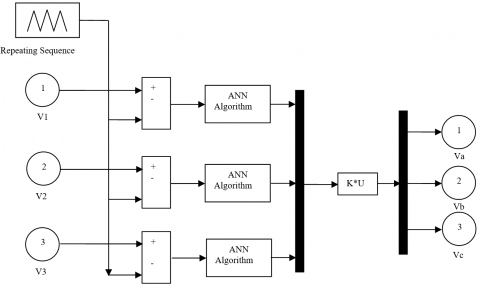
To improve the classical DPC performances, complimentary use of the NPWM technique is proposed. The principle of the NPWM technique is similar to the classical PWM strategy. Benbouhenni [25] explains this strategy carefully. The difference is using the ANN algorithm to replace the classical hysteresis comparators. As shown in Figure 20. Also, the NPWM technique is a simple modulation scheme and algorithm, minimized the harmonic distortion of current and power ripples compared to the classical PWM and SVPWM technique [47].
In this section, the type of neural network used is a backpropagation algorithm. The backpropagation algorithm is one of the most used supervised learning algorithms for neural networks. This algorithm was introduced in the 1980s by Rumelhart. The principle of this algorithm is based on a modification of the synaptic weights from a backpropagation of the error from the output to the entry layer, passing the hidden layer. On the other hand, this algorithm is a simple algorithm and robust compared to other algorithms. In function optimization problems with neural networks, the training algorithm is designed to determine the best network parameters in order to minimize network error. Various function optimization methods can be applied to neural networks model training. One of these methods is the Levenberg-Marquardt (LM) algorithm. This algorithm was developed by Kenneth Levenberg and Donald Marquardt. LM algorithm solves the problem of minimizing a nonlinear function numerically, very fast, and with a stable convergence. This algorithm uses the idea of backpropagation in the calculation of the Jacobian. The LM algorithm is a combination of the gradiant descent algorithm and the Gauss-Newton method.
In NPWM technique, we use one input layer, one hidden layer and an output layer. The input layer it consists of one neuron and one neuron for output layer. The hidden layer has 8 neurons. The parameters of the LM algorithms for the model system are shown in Table 4. In the LM algorithm, the error value is zero. On the other hand, the advantage of a LM algorithm is a robust and simple algorithm compared to the Gradient descent w/momentum & Adaptive LR backpropagation and Gradient descent with momentum. We use trainlm in Matlab/Simulink to accomplish the neural networks this is after determining the value of: Epoch, goal, mu, Lr, show, mc and Number of neurons in hidden layer (see Table 4).
Figure 20. Schematic diagram of NPWM technique
Table 4. Parameters of the LM algorithm
|
Parameters of the LM |
Values |
|
TrainParam.Lr |
0.005 |
|
TrainParam.goal |
0 |
|
TrainParam.mu |
0.9 |
|
TrainParam.eposh |
1000 |
|
TrainParam.show |
50 |
|
Number of hidden layer |
1 |
|
Number of hidden layer |
1 |
|
Number of layer 1 |
1 |
|
Number of layer 2 |
1 |
|
Number of neurons in hidden layer |
8 |
|
Number of neurons in layer 2 |
1 |
|
Number of neurons in layer 1 |
1 |
|
Coeff of acceleration of convergence (mc) |
0.9 |
|
Functions of activation |
Tensing, Purling, trainlm |
The ANN algorithm is one of the intelligent techniques used today. This algorithm based on observations and engineering experience. However, this algorithm is widely used for the AC machine and simplicity is the best advantage of the ANN algorithm. In the ANN algorithm, an exact mathematical model is not necessary. The design of the ANN algorithm helps in achieving minimized power ripple, harmonic distortion (THD) of stator current, a simple algorithm, and robustness against disturbances and is simple to implement compared to the traditional algorithms.
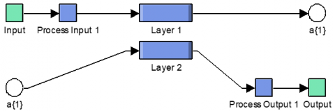
In this part, the ANN algorithm used is that of the backpropagation with LM algorithm. In this algorithm we used the following activation functions: Tensing, Purling and trainlm. This algorithm determines the initial weight and this is after determining the number of each input layer, output layer and hidden layer. The number of input and output layers imposed by the system. On the other hand, the number of hidden layers imposed by the backpropagation network. In backpropagation neural networks, the number of the hidden layers is one layer. There are several parameters of the LM algorithm that are shown in Table 5. The architecture of the ANN algorithm used to perform the DPC method is an ANN algorithm with one linear input node, 8 neurons in the hidden layer, and one neuron in the output layer. As shown in Figure 21.
Figure 21. Schematic diagram of ANN algorithm
The simulation results of the NDPC-NPWM method of a 1.5 MW DFIG are compared with the classical DPC method.
The controls system was tested under deferent operating conditions such as a sudden change of load reactive and active powers. The performance analysis is done with electromagnetic torque, harmonic distortion of stator current, reactive/active powers. DFIG used for the simulations has the following parameters: Pn = 1.5 MW, Vn = 398 V, f = 50 Hz, J = 1000 Kg.m2, fr= 0.0024 Nm/s, Ls = 0.0137 H, Rs = 0.012 $\Omega$, Rr = 0.021 $\Omega$, Lr = 0.0136 H, M = 0.0135 H [48, 49].
Table 5. LM algorithm
|
Parameters |
Values |
|
Number of hidden layer |
1 |
|
TrainParam.Lr |
0.005 |
|
Number of layer 1 |
1 |
|
Number of layer 2 |
1 |
|
TrainParam.show |
50 |
|
TrainParam.eposh |
1000 |
|
Coeff of acceleration of convergence (mc) |
0.9 |
|
Number of neurons in layer 1 |
1 |
|
TrainParam.goal |
0 |
|
TrainParam.mu |
0.9 |
|
Number of neurons in hidden layer |
8 |
|
Number of neurons in layer 2 |
1 |
|
Functions of activation |
Tensing, Purling, trainlm |
|
Net.trainParam.lr_inc |
1.05 |
|
Net.trainParam.lr_dec |
0.7 |
|
Net.trainParam.max_fail |
6 |
|
Net.trainParam.min_grad |
1e-5 |
|
Net.trainPram.time |
inf |
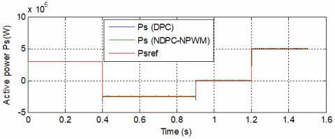
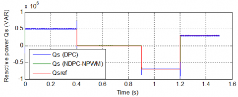
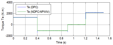
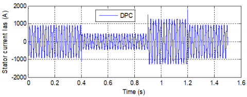
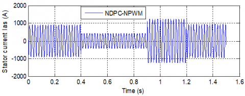
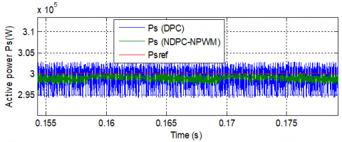
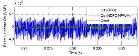
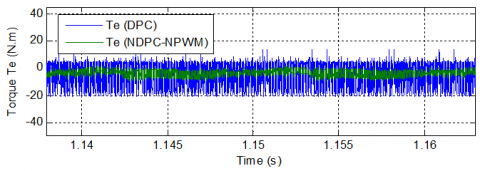
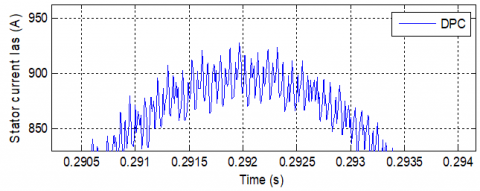
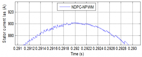
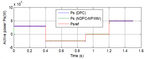
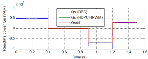
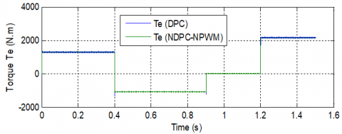
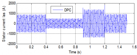
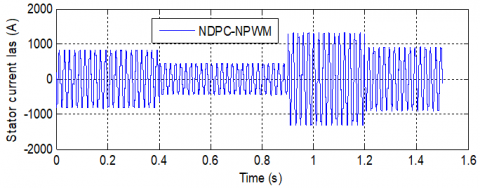
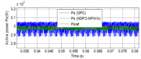
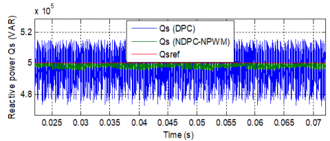
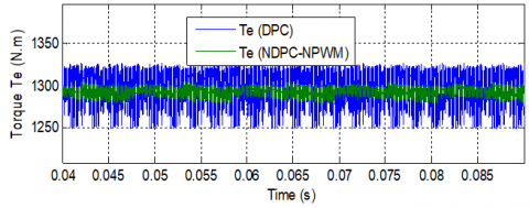
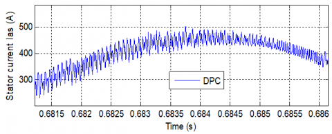
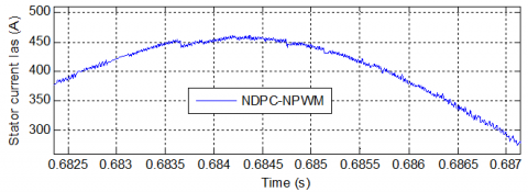
For the classical DPC and proposed DPC method, the active power, and reactive power tracks almost perfectly their reference values (Psref and Qsref) (See Figures 22 and 23). The reactive and active powers are decoupled from each other in the NDPC-NPWM with a rapid time response, without overshoot, and with a minimal static error compared to classical DPC strategy. Figure 24 shows the electromagnetic torque of the both DPC method. Figure 25 shows the stator current of the proposed DPC method and the traditional DPC technique. We can see that torque and stator current of the DFIG are proportional to the variation of active/reactive power reference values. Active power response comparing curves are shown in Figure 28. See figure the active power ripples are significantly reduced when the NDPC-NPWM method is in use. Figure 29 shows the reactive power responses of both the DPC method. It is found that the NDPC-NPWM method exhibits smooth response and lesser ripple in reactive power as compared to the classical DPC strategy and DPC with PI controller [25]. On the other hand, the NDPC-NPWM method minimized the torque ripples compared to the traditional DPC strategy (See Figure 30). Figure 31 shows the zoom in the stator current of both strategies. This figure shows that the ripples of stator current for the NDPC-NPWM method have minimized compared to the conventional DPC method.
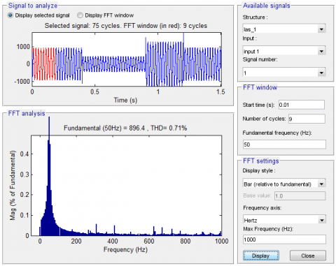
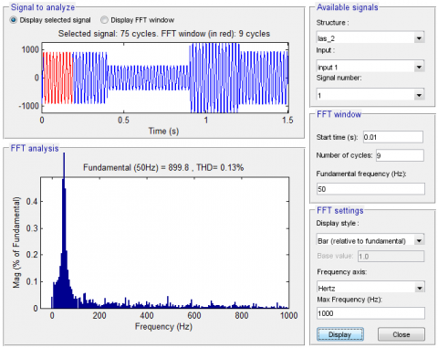
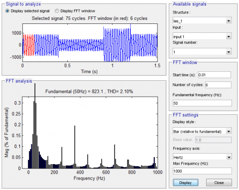
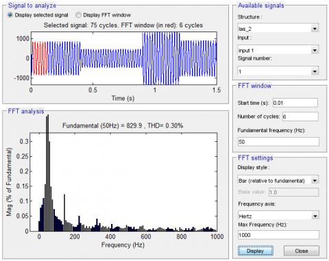
From the simulation results presented in Figures 26 and 27, it is apparent that the THD value of stator current for the NDPC-NPWM method is considerably reduced compared to conventional DPC method. Table 6 represents a comparative study between the proposed DPC method and several types of controls suggested in several articles. We can see the proposed DPC method minimized the THD value of current compared to DPC-PI, DPC, DPC-ANN, DPC-MRAC, FOC, SMC, FMC, DPC-T2FLC, and DPC-NFC. So, the proposed control can be said to be solid and robust.
Table 6. Comparative analysis of THD value (RTT)
|
|
THD (%) |
|
|
Ref. [44] |
DPC-PI |
2.59 |
|
DPC-ANN |
1.09 |
|
|
Ref. [50] |
DPC-T2FLC |
1.14 |
|
DPC-NFC |
0.78 |
|
|
Ref. [51] |
FOC |
3.7 |
|
Ref. [52] |
SMC |
3.05 |
|
FSMC |
2.85 |
|
|
Ref. [53] |
DPC-MRAC |
1.01 |
|
Proposed method |
DPC |
0.71 |
|
NDPC-NPWM |
0.13 |
|
Figure 22. Active power (RTT)
Figure 23. Reactive power (RTT)
Figure 24. Electromagnetic torque (RTT)
(a) DPC
(b) NDPC-NPWM
Figure 25. Stator current Ias (RTT)
Figure 26. Spectrum harmonic of stator current (DPC)
Figure 27. Spectrum harmonic of stator current (NDPC-NPWM)
Figure 28. Zoom in the active power (RTT)
Figure 29. Zoom in the reactive power (RTT)
Figure 30. Zoom in the electromagnetic torque (RTT)
(a) DPC
(b) NDPC-NPWM
Figure 31. Zoom in the stator current Ias (RTT)
4.2 Robustness test (RT)
In this part, the DFIG parameters have been intentionally changed such as the values of the resistances Rsand Rrare multiplied by 2 and the values of the inductances Lsand Lrare multiplied by 0.5. Simulation results are presented in Figures 32-37. As it’s shown by these figures, these variations present a clear effect on electromagnetic torque, reactive power, active power, and stator current curves and that the effect appears more important for the conventional DPC method than that with NDPC-NPWM (see Figures 38-41). On the other hand, these results show that the THD value of stator current in the NDPC-NPWM method has been minimized significantly (see Figures 36-37). Table 7 shows the comparative analysis of THD values. Thus, it can be concluded that the proposed NDPC-NPWM method is more robust than the conventional DPC strategy.
Figure 32. Active power (RT)
Figure 33. Reactive power (RT)
Figure 34. Electromagnetic torque (RT)
(a) DPC
(b) NDPC-NPWM
Figure 35. Stator current (RT)
Figure 36. Spectrum harmonic of stator current (DPC)
Figure 37. Spectrum harmonic of stator current (NDPC-NPWM)
Figure 38. Zoom in the active stator power (RT)
Figure 39. Zoom in the reactive stator power (RT)
Figure 40. Zoom in the torque (RT)
(a) DPC
(b) NDPC-NPWM
Figure 41. Zoom in the stator current (RT)
Table 7. Comparative analysis of THD value (RT)
|
|
THD (%) |
|
|
DPC |
NDPC-NPWM |
|
|
Stator current |
2.10 |
0.30 |
In this work, a new DPC scheme based on the ANN algorithm and NPWM technique for a DFIG-WT is presented. A comparison of this method with a traditional DPC method is elaborated by using different simulation tests. The results obtained showed the superiority of the proposed technique compared to the classical DPC method. The performances brought by the proposed technique appeared especially in the reduction of the DFIG powers ripples while keeping the robustness of the control. These results can actively contribute to improving the conditions for connecting the DFIG-based wind system to the electricity grid.
|
DFIG |
Doubly fed induction generator |
|
DPC |
Direct power control |
|
NSOSMC |
Neuro-second order sliding mode controller |
|
NSVPWM |
Neural space vector pulse width modulation |
|
NPWM |
Neural pulse width modulation |
|
PI |
Proportional-integral |
|
NSTSM |
Neural super-twisting sliding mode |
|
FPWM |
Fuzzy pulse width modulation |
|
ANFIS |
Adaptive network-based fuzzy inference system |
|
ANN |
Artificial neural network |
|
Lr, Ls |
Stator and rotor self-inductances, H |
|
Lm |
Mutual inductance, H |
|
Rr, Rs |
Stator and rotor resistances, Ω |
|
ѱr, ѱs |
Rotor and Stator flux vectors, Wb |
|
Is, Ir |
Rotor and stator current vectors, A |
|
Vs, Vr |
Rotor and stator voltage vectors, V |
|
Ps, Qs |
Active and reactive powers, Kw |
|
r, s |
Rotor, stator |
|
d, q |
Synchronous d-q axis |
[1] Fihakhir, A.M., Bouhamida, M. (2016). Nonlinear control of a doubly fed induction generator driven wind turbine. Electrotehnica Electronica Automatica (EEA), 64(2): 23-30. https://doi.org/10.1016/j.ijepes.2018.03.012
[2] Boudjema, Z., Taleb, R., Djerriri, Y., Yahdou, A. (2017). A novel direct torque control using second order continuous sliding mode of a doubly fed induction generator for a wind energy conversion system. Turkish Journal of Electrical Engineering & Computer Sciences, 25(2): 965-975. https://doi.org/10.3906/elk-1510-89
[3] Shehata, E.G., Gerges, M., Salama, M. (2013). Direct power control of DFIGs based wind energy generation systems under distorted grid voltage conditions. International Journal of Electrical Power & Energy Systems, 53: 956-966. https://doi.org/10.1016/j.ijepes.2013.06.006
[4] Rahul Charles, C.M., Vinod, V., Anju, J. (2018). Field oriented control of DFIG based wind energy system using battery energy storage system. Procedia Technology, 24: 1203-1210. https://doi.org/10.1016/j.protcy.2016.05.247
[5] Chowdhury, B., Chellapilla, S. (2006). Double-fed induction generator control for variable speed wind power generation. Electric Power Systems Research, 76(9): 786-800. https://doi.org/10.1016/j.epsr.2005.10.013
[6] Benbouhenni, H., Boudjema, Z., Belaidi, A. (2019). Indirect vector control of a DFIG supplied by a two-level FSVM inverter for wind turbine system. Majlesi Journal of Electrical Engineering. 13(1): 45-54.
[7] Morel, L., Godfroid, H., Mirzaian, A., Kauffmann, J.M. (1998). Double-fed induction machine: Converter optimization and field oriented control without position sensor. IEEE Proceedings: Electric Power Applications, 145(4): 360-368. https://doi.org/10.1049/ip-epa:19981982
[8] Hopfensperger, B., Atkinson, D., Lakim, R.A. (1999). Stator flux oriented control of a cascaded doubly-fed induction machine. IEEE Proceedings: Electric Power Applications, 146(6): 597-605. https://doi.org/10.1049/ip-epa:19990590
[9] Xu, L., Cartwright, P. (2006). Direct active and reactive power control of DFIG for wind energy generation. IEEE Transactions on Energy Conversion, 21(3): 750-758. https://doi.org/10.1109/TEC.2006.875472
[10] Benbouhenni, B. (2019). Intelligence indirect vector control of a DFIG based wind turbines. Majlesi Journal of Electrical Engineering, 13(3): 27-35.
[11] Benbouhenni, H. (2018). Comparative study between different vector control methods applied to DFIG wind turbines. Majlesi Journal of Mechatronic Systems, 7(4): 15-23.
[12] Benbouhenni, H., Boudjema, Z., Belaidi, A. (2018). Direct vector command based on three-level NSVM of a doubly fed induction generator for wind energy conversion. In 2018 International Conference on Applied Smart Systems (ICASS), pp. 1-8. https://doi.org/10.1109/ICASS.2018.8651957
[13] Benbouhenni, H., Boudjema, Z., Belaidi, A. (2019). Intelligent SVM technique of a multi-level inverter for a DFIG-based wind turbine system. International Journal of Digital Signals and Smart Systems, 3(1-3): 4-19. https://doi.org/10.1504/IJDSSS.2019.103372
[14] Benbouhenni, H., Boudjema, Z., Belaidi, A. (2018). DFIG-based wind turbine system using three-level neural space vector modulation technique. Majlesi Journal of Mechatronic Systems, 7(2): 35-45.
[15] Benbouhenni, H. (2019). A comparison study between fuzzy PWM and SVM inverter in NSMC control of stator active and reactive power control of a DFIG based wind turbine systems. International Journal of Applied Power Engineering (IJAPE), 8(1): 78-92.
[16] Benbouhenni, H. (2017). Comparison study between FPWM and NSVM inverter in neuro-sliding mode control of reactive and active power control of a DFIG-based wind energy. Majlesi Journal of Energy Management, 6(4): 15-23.
[17] Benbouhenni, H., Boudjema, Z., Belaidi, A. (2019). Using four-level NSVM technique to improve DVC control of a DFIG based wind turbine systems. Periodica Polytechnica Electrical Engineering and Computer Science, 63(3): 144-150. https://doi.org/10.3311/PPee.13636
[18] Benbouhenni, H. (2020). Comparison study between seven-level SVPWM and two-level SVPWM strategy in direct vector control of a DFIG-based wind energy conversion systems. International Journal of Applied Power Engineering (IJAPE), 9(1): 12-21. http://doi.org/10.11591/ijape.v9.i1.pp%25p
[19] Zhi, D.W., Xu, L. (2007). Direct power control of DFIG with constant switching frequency and improved transient performance. IEEE Transactions on Energy Conversion, 22(1): 110-118. https://doi.org/10.1109/TEC.2006.889549
[20] Jou, S., Lee, S., Park, Y., Lee, K. (2009). Direct power control of a DFIG in wind turbines to improve dynamic responses. J. Power Electron, 9(5): 781-790.
[21] Yaichi, I., Semmah, A., Wira, P., Djeriri, Y. (2019). Super-twisting sliding mode control of a doubly-fed induction generator based on the svm strategy. Periodica Polytechnica Electrical Engineering and Computer Science, 63(3): 178-190. https://doi.org/10.3311/PPee.13726
[22] Kadri, A., Marzougui, H., Bacha, F. (2019). Implementation of direct power control based on stator flux estimation using low-pass filter estimator for doubly fed induction generator–wind energy conversion system. Proceedings of the Institution of Mechanical Engineers, Part I: Journal of Systems and Control Engineering, 233(7): 764-778. https://doi.org/10.1177/0959651818818895
[23] Benbouhenni, H., Boudjema, Z., Belaidi, A. (2018). Sensorless twelve sectors implementation of neural DPC controlled DFIG for reactive and active powers ripples reduction. Majlesi Journal of Energy Management, 7(2): 13-21.
[24] Benbouhenni, H. (2019). Application of five-level NPC inverter in DPC-ANN of doubly fed induction generator for wind power generation systems. International Journal of Smart Grid, 3(3): 128-137. https://doi.org/10.1016/j.renene.2009.09.008
[25] Benbouhenni, H. (2019). Sliding mode with neural network regulateur for DFIG using two-level NPWM strategy. Iranian Journal of Electrical & Electronic Engineering, 15(3): 411-419. https://doi.org/10.22068/IJEEE.15.3.411
[26] Benbouhenni, H. (2018). A comparative study between DTC-NSTMC and DTC-FSTSMC control scheme for a DFIG-based wind turbine. Majlesi Journal of Energy Management, 7(4): 43-53.
[27] Benbouhenni, H. (2019). Direct power control of a DFIG fed by a seven-level inverter using SVM strategy. International Journal of Smart Grid, 3(2): 54-62.
[28] Benbouhenni, H. (2019). A comparative study between FSMC and FSOSMC strategy for a DFIG-based wind turbine system. Majlesi Journal of Mechatronic Systems, 8(2): 7-14.
[29] Benbouhenni, H., Boudjema, Z., Belaidi, A. (2018). Neuro-second order sliding mode control of a DFIG supplied by a two-level NSVM inverter for wind turbine system. Iranian Journal of Electrical & Electronic Engineering, 14(4): 362-373. https://doi.org/10.22068/IJEEE.14.4.362
[30] Benbouhenni, H., Boudjema, Z., Belaidi, A. (2020). Direct power control with NSTSM algorithm for DFIG using SVPWM technique. Iranian Journal of Electrical & Electronic Engineering, In Press.
[31] Benbouhenni, H. (2019). A direct power control of the doubly fed induction generator based on the three-level NSVPWM technique. International Journal of Smart Grid, 3(4): 216-225.
[32] Mustapha, J., Dheeraj, J., Mohammed, A., Abderrahim, B. (2018). Direct Power Neuro-Fuzzy Controller Scheme of Three-Phase PWM Rectifiers for Power Quality Improvement. Procedia Computer Science, 132: 595-605. https://doi.org/10.1016/j.procs.2018.05.013
[33] Benbouhenni, H., Boudjema, Z., Belaidi, A. (2020). Twelve sectors DPC control based on neural hysteresis comparators of the DFIG integrated to wind power. International Journal of Smart Grid-ijSmarGrid, 4(2).
[34] Harrage, A., Messalti, S. (2017). A variable step size fuzzy MPPT controller improving energy conversion of variable speed DFIG wind turbine. Revue des Energies Renouvelables, 20(2): 295-308.
[35] Abdelouahab, B., Fateh, K., Jean-Paul, G. (2009). Fuzzy-logic-based switching state selection for direct power control of three-phase PWM rectifier. IEEE Transactions on Industrial Electronics, 56(6): 1984-1992. https://doi.org/10.1109/TIE.2009.2014746
[36] Youcefa, B.E., Massoum, A., Barkat, S., Wira, P. (2020). Backstepping predictive direct power control of grid-connected photovoltaic system considering power quality issue. Majlesi Journal of Electrical Engineering, 14(1): 8-23.
[37] Serhoud, H., Benattous, D. (2017). Sensorless optimal power control of doubly fed induction wind generator based on extended Kalman filter. Electrotehnica, Electronica, Automatica, 65(3): 34-41.
[38] Harrage, A., Messalti, S. (2017). A variable step size fuzzy MPPT controller improving energy conversion of variable speed DFIG wind turbine. Revue des Energies Renouvelables, 20(2): 295-308.
[39] Mohammed, Y., Mohammed-Karim, F., Abdelkrim, M. (2014). A neural network based MPPT technique controller for photovoltaic pumping system. International Journal of Power Electronics and Drive Systems, 4(2): 241-255. https://doi.org/10.11591/ijpeds.v4i2.5875
[40] Zeddini, M.A., Sakly, R.P.A., Minouni, M.F. (2016). PSO-based MPPT control of wind-driven self-excited induction generator for pumping system. Renewable Energy, 95: 162-177. https://doi.org/10.1016/j.renene.2016.04.008
[41] Jang, J.S.R. (1993). ANFIS: Adaptive-Network-Based Fuzzy Inference System. IEEE Transactions on Systems Man & Cybernetics, 23: 665-685. https://doi.org/10.1109/21.256541
[42] Melin, P., Castillo, O. (2001). Intelligent control of complex electrochemical systems with a neuro-fuzzy-genetic approach. IEEE Trans. Industrial Electronics, 48(5): 951-955. https://doi.org/10.1109/41.954559
[43] Sun, Y., Xu, J., Qiang, H., Lin, G. (2019). Adaptive neural-fuzzy robust position control scheme for Maglev train systems with experimental verification. IEEE Trans. on Industrial Electronics, 66(11): 8589-8599. https://doi.org/10.1109/TIE.2019.2891409
[44] Benbouhenni, H., Boudjema, Z., Belaidi, A. (2020). Power ripple reduction of DPC DFIG drive using ANN controller. Acta Electrotechnica et Informatica, 20(1): 15-22. https://doi.org/10.15546/aeei-2020-0003
[45] Pichan, M., Rastegar, H., Monfared, M. (2013). Two fuzzy-based direct power control strategies for induction generators in wind energy conversion systems. Energy, 51: 154-162. https://doi.org/10.1016/j.energy.2012.12.047
[46] Heydari, E., Rafiee, M., Pichan, M. (2018). Fuzzy-genetic algorithm-based direct power control strategy for DFIG. Iranian Journal of Electrical and Electronic Engineering, 14(4): 353-361.
[47] Benbouhenni, H., Boudjema, Z., Belaidi, A. (2020). Comparison study between NPWM and NSVPWM strategy in FSMC control of stator reactive and active powers control of a DFIG-based wind turbine system. International Journal of Applied Power Engineering (IJAPE), 9(2): 159-172. http://doi.org/10.11591/ijape.v9.i2.pp%25p
[48] Benbouhenni, H., Boudjema, Z., Belaidi, A. (2019). Higher control scheme using neural second order sliding mode and ANFIS-SVM strategy for a DFIG-based wind turbine. International Journal of Advances in Telecommunications, Electrotechnics, Signals and Systems, 8(2): 17-28. http://dx.doi.org/10.11601/ijates.v8i2.263
[49] Benbouhenni, H. (2018). New hybrid five-level space vector modulation strategy to minimize current distortion and power ripple for a DFIG controlled by NSOSMC control. Majlesi Journal of Energy Management, 7(2): 33-44.
[50] Amrane, F., Chaiba, A. (2016). A novel direct power control for grid-connected doubly fed induction generator based on hybrid artificial intelligent control with space vector modulation. Rev. Roum. Sci. Tech.-Electrotechn. Et Energ, 61(3): 263-268.
[51] Amrane, F., Chaiba, A., Badr Eddine, B., Saad, M. (2016). Design and implementation of high performance field oriented control for grid-connected doubly fed induction generator via hysteresis rotor current controller. Rev. Roum. Sci. Tech.-Electrotechn. Et Energ, 61(4): 319-324.
[52] Boudjema, Z., Meroufel, A., Djerriri, Y., Bounadja, E. (2013). Fuzzy sliding mode control of a doubly fed induction generator for energy conversion. Carpathian Journal of Electronic and Computer Engineering, 6(2): 7-14.
[53] Amrane, F., Chaiba, A., Mekhilef, S. (2016). High performances of grid-connected DFIG based on direct power control with fixed switching frequency via MPPT strategy using MRAC and neuro-fuzzy control. Journal of Power Technologies, 96(1): 27-39.