Reza Alayi* | Reza Nemati | Ali Shamel | Alibakhsh Kasaeian | Maedeh Kiani Sarkaleh | Mohammad Hossein Ahmadi
OPEN ACCESS
Today, the issue of energy is very important for this purpose utilizing energy losses is very important. One of these ways is the use of heat dissipation in thermal systems. many attempts are doing to develop cogeneration systems taking into account cost, safety and environmental issues that gas turbine system of such a system can be noted. One important application of gas turbine cycle because of cycle high temperatures is to use them for hybrid cycle. For this purpose, the solid oxide fuel cell can be used that is very suitable for boiler input due to the high air temperature. In this regard, two different scenarios have been considered. In the first scenario, only the gas turbines cycle is used where the first law efficiency, second law efficiency and exergy destruction of the total cycle are 42.02 %, 50.28 % and 38960 KW, respectively. In this case, the most exergy destruction is related to combustion chamber. In the second scenario, fuel cell gas turbine cycle will be used, where the first law efficiency, second law efficiency and exergy destruction of the total cycle are 46 %, 56.84 % and 810 740 KW, respectively. In this case, the most exergy destruction is related to combustion chamber.
modeling, energetic, exergetic, SOFC, gas turbine
Although fuel cells have recently been proposed as a way to produce electrical energy, its history is dates back to the 19th century and the work of British Scientist Sir William Grove. He built the first fuel cell in 1839 with exemplify water electrolysis reaction during the reverse reaction in the presence of platinum catalyst. Several attempts were made in the early twentieth century in order to fuel cell development that neither was successful due to lack of scientific understanding [1-2-3].
But today, due to the growing trend of energy consumption in the world and its impact on the environment, using the methods and power production systems, in addition to high efficiency, have less pollution have been place in the priority. High-temperature fuel cells such as solid oxide fuel cells, due to high efficiency in converting chemical energy of fossil fuels into electrical energy and low emission of pollutants are one of these cases [3-4]. The high temperature fuel cell combined with power generation cycle has caused that the resulted hybrid system to be considered as a proposal for new heating systems [5-6].
Hybrid systems are power generation systems in which a heat engine such as gas turbines with a non-heat engine, such as fuel cells has direct and indirect combination [7-8]. Due to the high efficiency of this type of hybrid systems than gas turbine or only fuel cell as well as to reduce emissions, the systems will play significant impact on how to power generation and energy in the near future. Research results show that hybrid system efficiency is much higher than the efficiency of gas micro turbines and fuel cells alone that with this type of system can achieved up than 65 % higher efficiency [9-10].
In 2016, Shamel and et al. [11] conducted a research called designing a PID controller to control a fuel cell voltage using the imperialist competitive algorithm. In 2017, Siddiqui et al. [12] conducted a research called analysis and performance assessment of a new solar-based multigeneration system integrated with ammonia fuel cell and solid oxide fuel cell-gas turbine combined cycle, which showed that Increase of 19.3% in energy efficiency as compared to single generation system. In 2017, Choudhary et al. [13] undertook a research on the novel and optimal integration of SOFC-ICGT hybrid cycle: Energy analysis and entropy generation minimization. In 2017, Sadeghi et al. [14] conducted a research on the energy and economic comparison of SOFC-GT, MCFC-GT, and SOFC-MCFC-GT hybrid systems. In 2018, Sghaier et al. [15] presented energetic and exergetic parametric study of a SOFC-GT hybrid power plant. Finally, which showed that the increase of the ambient temperature, the humidity and the extraction fraction reduces the overall power plant efficiencies. In 2018 Khani et al. [16] conducted energy and Exergy Analysis of a Novel Combined Power/Cooling Production Cycle Based on Solid Oxide Fuel Cell. In 2018, Pirkandi et al. [17] conducted a study on a thermodynamic performance analysis of three solid oxide fuel cell and gas microturbine hybrid systems for application in auxiliary power units. In 2018, Gholamian et al. [18] conducted an evolutionary based multi-criteria optimization of an integrated energy system with SOFC, gas turbine, and hydrogen production via electrolysis. In 2019, Roy et al. [19] conducted a research on the techno-economic and environmental analyses of a biomass based system employing solid oxide fuel cell, externally fired gas turbine and organic Rankine cycle.
The aim of this study was to investigate the thermodynamic performance and exergy of the hybrid system gas turbine-powered solid oxide fuel cell to play the fuel cell in a hybrid cycle and supply the greater part of their production power.
Today, the major share of electrical energy generated by the nuclear power plants, but nuclear power plants compared to the fossil power plants are less efficient. Given that the source of enriched uranium fuel is expensive, therefore solutions that can optimize energy conversion systems such as hybrid power plants will have a great importance. In addition to energy, the proposed solutions must consider economic issues of this type of power plant due to the high initial investment and their operation costs. Exergy analysis in power plants helps engineers and analysts to increase efficiency and reduce energy losses that from the economic point of view are fully justified.
Energy Conservation law is one of the fundamental laws of nature. This principle says energy while the interaction can be converted from one form to another, but its whole remains constant; that is energy cannot be created or destroyed. The first law of thermodynamics states the Energy Conservation law and says that energy is one of the thermodynamic properties. The second law says energy has quantity and quality and the actual processes occur in order to reduce energy quality.
A division of analyzes presented in the field of thermodynamics. Then, the energy analysis processes have been investigated and a brief description of the first and second law of thermodynamics for cycle is given. Finally, a detailed survey will be discussed because of the importance of Exergy analysis.
The analysis based on Second Law of Thermodynamics that so-called Exergy analysis has been the head of thermodynamic in the last three decades. Exergy analysis though historically goes back to the years before 1970, with the energy crisis in the early seventies that interest into the analysis based on the Second Law exponentially growing.
Exergy is the maximum useful work that can obtain from the amount of energy or the flow of materials. According to the second law of thermodynamics, in each actual process, entropy production is synonymous with the destruction of exergy in the process. The main objective of Exergy analysis is to identify the location and amount of different irreversible processes in a thermodynamic system that recognizing that they can determine the amount and how to improve the performance of the system.
Exergy analysis, using the first and second laws of thermodynamics at the same time while definition of the environment as a reference will be trying to answer the following questions:
1. The maximum work achievable from a heat engine such as thermal power plant
2. The minimum work required in refrigeration cycles
3. Implementation with minimal entropy production processes.
In thermo-economic analysis, the economic value of materials and energy that enters or exits the system is considered. In this analysis we tried to establish a balance between the costs of energy flow by applying economic concepts with thermodynamic concepts and giving economic value to the flow of energy and exergy in such a way that thermodynamic cycle product occurs with a minimum total cost.
As Exergy analysis, thermo-economic analysis as well has a particular interest from the early 70's. And most recently, the so-called Exergy-economic is common.
Exergy analysis methods, thermo-economic analysis and irreversible thermodynamics define the loss in different thermodynamic processes. It seems the next logical step in the research should be focused to optimum design of processes and devices of a system, so that losses may be reduced to minimum. This design has been resulted in a relatively new activity in the thermodynamic that so called design with a minimum production of entropy or thermodynamic design.
In thermodynamic design, the key work is that thermodynamic cycle design methods and its devices to be modified so that production of entropy in total system has the least possible amount. For example, in the design of heat exchanger try to select dimensions of fluid passage channels such that, in addition to the mass flow rate, entropy is also produced at least. As another example, the size of the fins in the heat exchangers must be chosen such that the required heat rate is transfer and at the same time minimize the entropy production.
Irreversibility of the machine is mainly caused by two factors heat transfer and fluid flow friction. In most cases, reduce the irreversibility leads to increase an irreversible in other machine. Therefore, in thermodynamic designing try to specified the minimum irreversibility point in total devices of a system.
As mentioned earlier, thermodynamic modeling is in fact the result of a change in research methodology. Modeling and different methods of operations research for years have been used on a limited basis in various fields of science, but their use has taken significant growth in the last decade. Usually, to achieve certain theories associated with several assumptions that in addition to these assumptions, tests are also being carried out under conditions. These tests, in addition to high costs, in some cases associated with risks. In this context, thermodynamic modeling as a low-cost and safe tool finds a special place in scientific research. Using modeling to search was presented for the first time in space research and then in nuclear research.
Mass and energy balances for a steady state control volume is as follow:
$\sum_{i n}\dot m-\sum_{o u t}\dot m=0$ (1)
$\sum_{i n} m h+\sum_{j} \cdot Q_{j}=\sum_{o u t} m h+\sum_{k} \dot{W}_{k}$ (2)
where subscripts in and out are input and output flow to control volume, respectively. And is referred to heat transfer from control surface, work done, mass flow and fluid enthalpy Cycle First Law Return is calculated as follows:
$\eta_{I}=\frac{\dot{W}_{net}}{\dot{Q}_{i n}}$ (3)
In the above equation, represents the heat entering the cycle and is network by cycle. To calculate the net cycle work in hybrid cycle, equation 4 is used [19].
$\dot{W}_{n e t}=\dot{W}_{t}-\dot{W}_{\operatorname{comp}}$ (4)
In the above equation, and are the work done by the turbine and work required for compressors, respectively.
Exergy as well as energy has several components. In the absence of nuclear fields, magnetic, electrical effects and surface tension could be wrote the following equation for flow Exergy of a material ($\vec{E}_{j}$):
\({{\dot{E}}_{j}}={{\dot{E}}_{k}}+{{\dot{E}}_{p}}+{{\dot{E}}_{ph}}+{{\dot{E}}_{di}}+{{\dot{E}}_{ch}}\) (5)
In this equation:
$\dot{E}_k$ : Flow kinetic Exergy of material that is obtained from the following equation:
$\dot{E}_{k}=\dot{m} \times \frac{V^{2}}{2}$ (6)
$\dot{E}_p$ : Flow potential Exergy of material that is obtained from the following equation:
$\dot{E}_{p}=\dot{m} \times g \times Z$ (7)
$\dot{E}_{p h}$ : Physical Exergy (thermomechanical) is the most accessible work of a substance in a condition that substance from its initial state while a completely reversible process and just heat exchange with the environment reaches to a limited dead state (pressure P0 and temperature T0)
Its value per unit mass flow rate is derived from the following equation:
$e_{p h}=\left(h-h_{0}\right)-T_{0}\left(s-s_{0}\right)$ (8)
Exergy flow physical change from state1 matter to the second is:
$e_{p h 2}-e_{p h 1}=\left(h_{2}-h_{1}\right)-T_{0}\left(s_{2}-s_{1}\right)$ (9)
$\dot{E}_{p h}=\dot{m}\left[\left(h-h_{0}\right)-T_{0}\left(s-s_{0}\right)\right]$ (10)
$\dot{E}_{d i}$ : Diffusion Exergy is the most accessible work from a substance when that substance is reached from the limited dead state to completely dead (pressure P0,X and temperatureT0). This pressure is the partial pressure of that substance in the environment.
$\dot{E}_{c h}$ : Chemical Exergy of the accessible work from a material produced in the environmental condition (pressure P0 and temperatureT0), so, that the substance provide chemical reaction with the components of the environment and the products eventually reach the state of environment.
In the hybrid cycle, the physical components before the combustion chamber and the Exergy physical and chemical components after the combustion chamber is considered.
This theorem states that Exergy destruction amounts to a volume control if the environment is in the absolute temperature T0, is derived from the following equation:
$\dot{I}=T_{0} \dot{S}_{g e n}$ (11)
In this equation, $\dot{S}_{g e n}$ is net entropy production in volume control and is calculated as follows:
$\dot{S}_{g e n}=\frac{d S_{c v}}{d t}-\sum_{j} \frac{\dot{Q}_{j}}{T_{j}}-\left(\sum_{i n} \dot{m} s-\sum_{o u t} \dot{m} s\right) \geq 0$ (12)
In the above equation Tj is the surface temperature where heat $\dot{Q}_{j}$ is transferred.
Based on the concept of Exergy, for a system that works in steady state and has input and output Exergy, Exergy balance is defined as follows:
$\sum_{i n} \dot{m} e+\sum_{j}\left(1-\frac{T_{0}}{T_{j}}\right) \times \dot{Q}_{j}-\sum_{o i t} \dot{m} e+\sum_{k} \dot{W}_{k}=\dot{E}_{D, c v}$ (13)
In the above equation, $\dot{E}_{D, c v}$ is Exergy destruction into the volume control and e shows the Exergy related to the substance flow. The second term on the left side of the equation represents Exergy of heat transfer.
The Return of Cycles Second Law is defined as follows:
$\eta_{I I}=\frac{\dot{W}_{n e t}}{\dot{E}_{in}}$ (14)
In the above equation, $\dot{E}_{i n}$ is refers to the Exergy of total input into cycle. Given that Exergy released in the combustion chamber can be considered as the total input Exergy, so the hybrid cycle can be written as:
$\dot{E}_{i n}=\dot{Q}_{c o r e}\left(1-\frac{T_{0}}{T_{r}}\right)$ (15)
In the above equation, $\dot{Q}_{\text {core}}$ and Tr is the heat generated in the reactor and shell temperature of the reactor core, respectively. From the Exergy balance 13, the parts of a cycle as volume control can be achieved by the following general relationship:
$\dot{E}_{F, k}=\dot{E}_{P, k}+\dot{E}_{D, k}+\dot{E}_{L, k}$ (16)
In the above equation, $\dot{E}_{F, k}$ refers to input Exergy rate to the volume control as the fuel Exergy, $\dot{E}_{P, k}$ , product Exergy rate or produced by the volume control, $\dot{E}_{D, k}$, Exergy destruction in that component due to its irreversible and $\dot{E}_{L, k}$ is Exergy losses or Exergy discarded in that component.
Exergy balance for total cycle can be obtained as follows:
$\dot{E}_{F, t o t}=\dot{E}_{P, t o t}+\sum_{k} \dot{E}_{D, k}+\dot{E}_{L, t o t}$ (17)
In order to better compare of the results, we use the Exergy destruction ratio 1 as a percentage which is obtained from the following equation:
$y_{k}=\left(\frac{\dot{E}_{D, k}}{\dot{E}_{F, t o t}}\right) \times 100$ (18)
$y_{k}^{*}=\left(\frac{\dot{E}_{D, k}}{\dot{E}_{D, t o t}}\right) \times 100$ (19)
The numerical results obtained from the analyses on the cycle are studied. These data of the simulation cycle using equations have been used in EES software in table 1.
Table 1. Energy analysis of gas turbine cycle
|
ex (kj/kmol) |
s (kj/kmol.k) |
h (kj/kmol) |
P (bar) |
T (K) |
Material flow |
State point |
|
0 |
199,2 |
-4712 |
1,013 |
298,2 |
air |
1 |
|
8681 |
201,4 |
4631 |
10,13 |
610,8 |
air |
2 |
|
12997 |
212,3 |
12180 |
9,624 |
850 |
air |
3 |
|
30959 |
235,1 |
8971 |
9,142 |
1520 |
Combustion product |
4 |
|
11839 |
238,2 |
-9235 |
1,099 |
1011 |
Combustion product |
5 |
|
6878 |
230,3 |
-16548 |
1,066 |
793,1 |
Combustion product |
6 |
|
1015 |
211,4 |
-28048 |
1,013 |
429 |
Combustion product |
7 |
|
79,29 |
6,601 |
1920 |
20 |
298,2 |
water |
8 |
|
16495 |
114,2 |
50420 |
20 |
485,6 |
water |
9 |
|
830476 |
165,7 |
-74595 |
12 |
298,2 |
methane |
10 |
As a result, for the net work of hybrid cycle gas turbine and SOFC, we have:
$\dot{W}_{n e t}=74163 k W$
For the second law efficiency, we have:
$\eta_{I I, c y c}=56.48 \%$
SOFC increases the cycle work and therefore the cycle Exergy output. As a result, the second law or Second Law Exergy efficiency will increase to 56.48. It should be noted that the addition of SOFC, in addition to raising the efficiency of the exergy second law increases total exergy destruction. In this case, the fuel cell voltage will be 0.76 voltages.
The results of the exergic analysis of hybrid cycle significantly increased the amount of Exergy destruction. And that is why in SOFC that methane fuel is a significant Exergy has entered the cycle. And this in turn, in each volume control increases Exergy destruction due to existing relationships in the previous season. According to the results, it is clear that before SOFC, due to small variations of Exergy, exergy destruction rate slightly increased.
Table 2. Hybrid cycle energy of gas turbine power analysis and SOFC
|
ex (kj/kmol) |
s (kj/kmol.k) |
h (kj/kmol) |
P (bar) |
T (K) |
Material flow |
State point |
|
0 |
199,2 |
-4712 |
1,013 |
298,2 |
air |
1 |
|
8681 |
201,4 |
4631 |
10,13 |
610,8 |
air |
2 |
|
12977 |
212,3 |
12180 |
9,624 |
850 |
air |
3 |
|
15178 |
215,9 |
15443 |
9,624 |
950 |
Combustion product |
4 |
|
30677 |
235,2 |
12592 |
8,685 |
1520 |
Combustion product |
5 |
|
11944 |
238,2 |
-5252 |
1,099 |
1018 |
Combustion product |
6 |
|
6941 |
230,4 |
-12599 |
1,066 |
799,5 |
Combustion product |
7 |
|
1184 |
212,8 |
-23595 |
1,013 |
451,3 |
Combustion product |
8 |
|
79,29 |
6,601 |
1920 |
20 |
298,2 |
water |
9 |
|
16495 |
114,2 |
50420 |
20 |
485,6 |
water |
10 |
|
830476 |
165,7 |
-74595 |
12 |
298,2 |
methane |
11 |
|
830476 |
165,7 |
-74595 |
12 |
298,2 |
methane |
12 |
Table 3. Exergy Analysis of gas turbines cycle and SOFC
|
ED,K(kw) |
|
|
2208 |
Air compressor |
|
2751 |
Air preheter |
|
3043 |
turbine |
|
774310 |
sofc |
|
21633 |
Combustion Chamber |
|
6974 |
hrsg |
|
810740 |
totall |
Figure 1. Effect of input temperature of compressor on compressor work
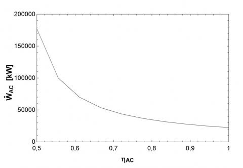
Figure 2 display the effect of compressor efficiency on compressor work. By increasing the efficiency of the compressor, the compressor work is reduced and net working cycle will increase. It is worth noting that the high level of net working represents net output Exergy is high.
Figure 3 is shown the effect of compressor inlet temperature on compressor Exergy destruction. Increase in compressor inlet temperature will increase compressor Exergy destruction and this is because the Fuel cycles Exergy will increase significantly that have negative impact on total cycle Exergy destruction.
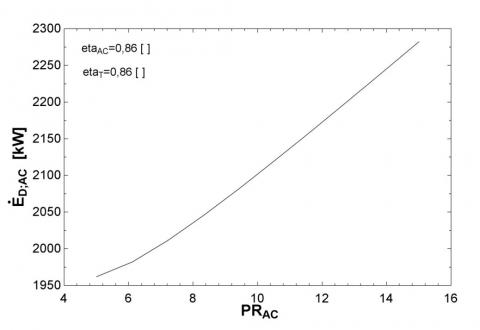
Figure 4 is shown the effect of compressor pressure ratio on compressor Exergy destruction. Increase in compressor pressure ratio will increase the compressor Exergy destruction. This is because the Fuel cycles Exergy will increase significantly that have negative impact on total cycle Exergy destruction.
Figure 2. Effect on compressor efficiency on Compressor work
Figure 3. Impact of compressor inlet temperature on compressor Exergy destruction
Figure 4. Impact of compressor pressure ratio on compressor Exergy destruction
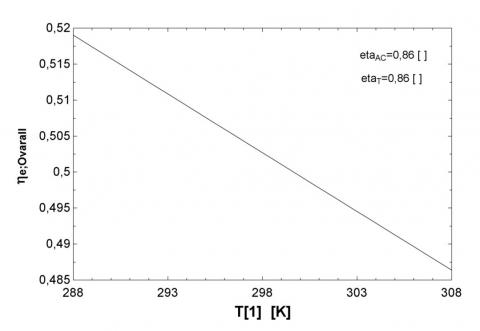
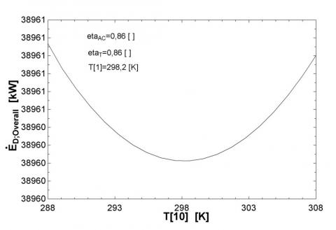
Figure 5 is shown the effect of compressor inlet temperature on total Exergy efficiency. Increase in compressor inlet temperature will increase compressor Exergy destruction and this has negative impact on total cycle Exergy destruction. So in general, the increase of compressor inlet temperature will have a negative impact on the first or second law.
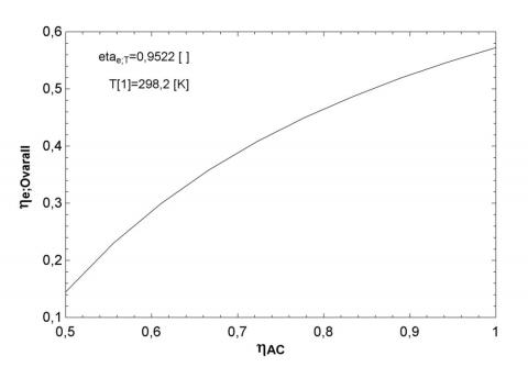
Figure 6 is shown the effect of compressor efficiency on total Exergy efficiency. Increasing the efficiency of the compressor reduces the compressor work rate. As a result, net working cycle is increased. Increase in net working cycle leads to an increase cycle product Exergy and in turn total cycle Exergy efficiency.
Figure 5. The impact of the compressor inlet temperature on total Exergy efficiency
Figure 6. the impact of the compressor efficiency on total Exergy efficiency
Figure 7 is shown the effect of the combustion chamber inlet temperature on the combustion chamber Exergy destruction. We will see that by increasing the inlet temperature of the combustion chamber, the combustion chamber destruction Exergy is increased. This is because that as temperatures rise, Exergy of Fuel combustion chamber or combustion chamber input Exergy will be increases.
Figure 8 is shown the effect of inlet temperature of the combustion chamber on total Exergy destruction. According to the results obtained in the previous section, by increasing the inlet temperature of the combustion chamber, Exergy of combustion chamber and in turn total Exergy destruction will be reduced. It should be noted that increasing the total amount of Exergy destruction, total efficiency of the cycle second Law is reduced. On the other hand, it must be said that with the increase of combustion chamber inlet temperature, total cycle inlet Exergy will be rises which leads to decrease the rate of the second law efficiency.
Figure 7. The effect of the combustion chamber inlet temperature on the combustion chamber Exergy destruction
Figure 8. The effect of the combustion chamber inlet temperature on total Exergy destruction
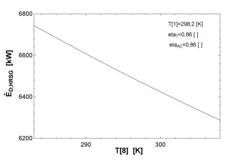
Figure 9 is shown the effect of HRSG water inlet temperature on HRSG Exergy destruction. Water inlet temperature increase makes Exergy amount of waste water was low in HRSG and this in turn reduces total Exergy destruction. Results of reduce total Exergy destruction we see in Figure 10.
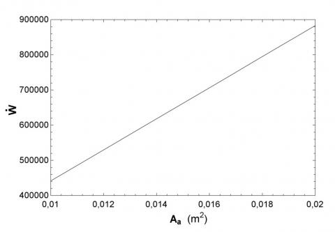
Figure 11 is shown the effect of area on SOFC the Production energy. It is known that by increasing the area of fuel cell, the fuel cell output will increase. So always choose a larger area will be in our favor.
Figure 9. The effect of HRSG water inlet temperature on the Exergy destruction HRSG
Figure 10. The effect of HRSG water inlet temperature on total Exergy destruction
Figure 11. Impact of area on the productive energy SOFC
Figure 12. Impact of cell inlet temperature on productive energy SOFC
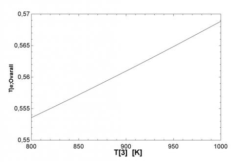
Figure 13. Impact of output temperature from SOFC on the Exergy efficiency of total hybrid cycle
Figure 12 is shown the effect of cell inlet temperature on energy efficiency SOFC. It is known that by increasing the cell inlet temperature, the reaction is carried out at a higher temperature in SOFC and causes the voltage and productive work became more in SOFC. This leads to increased efficiency of the first and second law as Figure 13.
[1] Choudhary T, Sahu MK. (2019). Energy and exergy analysis of solid oxide fuel cell integrated with gas turbine cycle — “A Hybrid Cycle”. In Renewable Energy and its Innovative Technologies, pp. 139-153. https://doi.org/10.1007/978-981-13-2116-0_12
[2] Choudhary T, Sahu M, Krishna S. (2017). Thermodynamic analysis of solid oxide fuel cell gas turbine hybrid system for aircraft power generation. SAE Technical Pape 2017-01-2062. https://doi.org/10.4271/2017-01-2062
[3] Habibollahzade A, Gholamian E, Behzadi A. (2019). Multi-objective optimization and comparative performance analysis of hybrid biomass-based solid oxide fuel cell/solid oxide electrolyzer cell/gas turbine using different gasification agents. Applied Energy 233: 985-1002. https://doi.org/10.1016/j.apenergy.2018.10.075
[4] Lee YD, Ahn KY, Morosuk T, Tsatsaronis G. (2018). Exergetic and exergoeconomic evaluation of an SOFC-Engine hybrid power generation system. Energy 145: 810-822. https://doi.org/10.1016/j.energy.2017.12.102
[5] Ebrahimi M, Moradpoor I. (2016). Combined solid oxide fuel cell, micro-gas turbine and organic Rankine cycle for power generation (SOFC–MGT–ORC). Energy Conversion and Management 116: 120-133. https://doi.org/10.1016/j.enconman.2016.02.080
[6] Choudhary T. (2017). Thermodynamic assessment of SOFC-ICGT hybrid cycle: Energy analysis and entropy generation minimization. Energy 134: 1013-1028. https://doi.org/10.1016/j.energy.2017.06.064
[7] Eveloy V, Karunkeyoon W, Rodgers P, Al Alili A. (2016). Energy, exergy and economic analysis of an integrated solid oxide fuel cell–gas turbine–organic Rankine power generation system. International Journal of Hydrogen Energy 41(31): 13843-13858. https://doi.org/10.1016/j.ijhydene.2016.01.146
[8] Eisavi B, Chitsaz A, Hosseinpour J, Ranjbar F. (2018). Thermo-environmental and economic comparison of three different arrangements of solid oxide fuel cell-gas turbine (SOFC-GT) hybrid systems. Energy Conversion and Management 168: 343-356. https://doi.org/10.1016/j.enconman.2018.04.088
[9] Saebea D, Magistri L, Massardo A, Arpornwichanop A. (2017). Cycle analysis of solid oxide fuel cell-gas turbine hybrid systems integrated ethanol steam reformer: Energy management. Energy 127: 743-755. https://doi.org/10.1016/j.energy.2017.03.105
[10] Ahmadi M, Sadaghiani M, Pourfayaz F, Ghazvini M, Mahian O, Mehrpooya M, Wongwises S. (2018). Energy and exergy analyses of a solid oxide fuel cell-gas turbine-organic Rankine cycle power plant with liquefied natural gas as heat sink. Entropy 20(7): 484. https://doi.org/10.3390/e20070484
[11] Shamel A, Marefati M, Alayi R, Gholaminia B, Rohl H. (2016). Designing a PID controller to control a fuel cell voltage using the imperialist competitive algorithm. Advances in Science and Technology Research Journal 10(30): 176-181. https://doi.org/10.12913/22998624/62629
[12] Siddiqui O, Dincer I. (2017). Analysis and performance assessment of a new solar-based multigeneration system integrated with ammonia fuel cell and solid oxide fuel cell-gas turbine combined cycle. Journal of Power Sources 370: 138-154. https://doi.org/10.1016/j.jpowsour.2017.10.008
[13] Choudhary T. (2017). Novel and optimal integration of SOFC-ICGT hybrid cycle: Energy analysis and entropy generation minimization. International Journal of Hydrogen Energy 42(23): 15597-15612. https://doi.org/10.1016/j.ijhydene.2017.04.277
[14] Sadeghi S. (2017). Energy and economic comparison of SOFC-GT, MCFC-GT, and SOFC-MCFC-GT hybrid systems. Iranian Journal of Hydrogen & Fuel Cell 4: 275-287. https://doi.org/10.22104/ijhfc.2018.2708.1163
[15] Sghaier SF, Khir T, Brahim AB. (2018). Energetic and exergetic parametric study of a SOFC-GT hybrid power plant. International Journal of Hydrogen Energy 43(6): 3542-3554. https://doi.org/10.1016/j.ijhydene.2017.08.216
[16] Khani L, Mahmoudi SMS, Chitsaz A. (2018). Energy and exergy analysis of a novel combined power/cooling production cycle based on solid oxide fuel cell. In Exergy for A Better Environment and Improved Sustainability 1: 1293-1309. https://doi.org/10.1007/978-3-319-62572-0_83
[17] Pirkandi J, Jahromi M, Sajadi SZ, Ommian M. (2018). Thermodynamic performance analysis of three solid oxide fuel cell and gas microturbine hybrid systems for application in auxiliary power units. Clean Technologies and Environmental Policy 20(5): 1047-1060. https://doi.org/10.1007/s10098-018-1534-2
[18] Gholamian E, Hanafizadeh P, Habibollahzade A, Ahmadi P. (2018). Evolutionary based multi-criteria optimization of an integrated energy system with SOFC, gas turbine, and hydrogen production via electrolysis. International Journal of Hydrogen Energy 43(33): 16201-16214. https://doi.org/10.1016/j.ijhydene.2018.06.130
[19] Roy D, Samanta S, Ghosh S. (2019). Techno-economic and environmental analyses of a biomass based system employing solid oxide fuel cell, externally fired gas turbine and organic Rankine cycle. Journal of Cleaner Production 225: 36-57. https://doi.org/10.1016/j.jclepro.2019.03.261