OPEN ACCESS
This paper describes an experimental greenhouse environment inspection vehicle which is loaded with ZigBee terminal nodes and various environment inspection sensors and can measure greenhouse environmental parameters in real time. The master controller of the greenhouse environment inspection vehicle is designed with 51 single-chip microcomputers as the core. Through sensors loaded on the ZigBee terminal nodes, the temperature, illumination intensity, and humidity of the greenhouse are measured and the acquired data are sent to the console. The serial port control of the greenhouse inspection vehicle utilizes an MFC interface and button control on the vehicle through the ZigBee coordinator.
ZigBee, Z-Stack, data acquisition, button control, serial port control.
The growth process of crops is very vulnerable to the surrounding environment. Greenhouse technology could be used to cultivate crops, and through the monitoring and control of environmental factors, such as temperature, humidity, light, and other environmental factors, crop quality and yield could be improved. Greenhouse system is a complex system with multivariable, nonlinear and high time-delay, and the internal factors are strongly coupled. To accurately control greenhouse environmental factors, the first task is data acquisition; of temperature, humidity, light, and other environmental factors. However, the vast majority of existing greenhouse environment detection and control system need to build sensor networks [1-9], as they are expensive to implement in small greenhouses or laboratory greenhouses. Greenhouse environmental temperature is a parameter that is constantly and slowly changing and can be monitored by a greenhouse environment inspection vehicle loaded with ZigBee terminal nodes and various environment inspection sensors. This vehicle can acquire greenhouse environmental parameters in real time, and then the data it sends to the console can be used to make adjustments to the greenhouse environment as necessary. The system is low in cost and can be arranged quickly and easily, making it potentially very valuable and effective for farmers and others tasked with managing greenhouse facilities.
The overall structure of the proposed system is shown in Fig. 1.Sensors connected to the ZigBee terminal nodes monitor the greenhouse environmental parameters while sen ding action commands to the master controller of the inspection vehicle; the master controller sends concrete movement commands to the driver to make the vehicle move. The operator can also refer to the MFC interface of the console, and send control orders and environment inspection orders through PC serial port to the ZigBee coordinator. After receiving orders from the PC and through the router, the coordinator sends them to the ZigBee terminal nodes to execute concrete tasks [2]. Those nodes carry out environmental inspection of the greenhouse and drive the vehicle, thus realizing PC serial port remote control. There also are buttons on the coordinator which the operators can press remotely control the vehicle’s movement, and a gyro sensor that ensures the vehicle stays balanced while moving.
Figure 1. System structure
3.1 Control circuit design
The information transformation section was established with CC2530 as the core. It altogether includes the CC2530 single-chip microcomputer as well as a crystal oscillator, antenna interface, antenna mast, I/O extending interface circuit, power circuit, and LED circuit [3-7]. The master controller of the inspection vehicle contains AT89C52 as the core, and the MENTORII contains L293D as the core [4]. The master controller circuit includes a matrix keyboard, single-chip microcomputer minimum system, display socket, and pin extending circuit [8].
3.2 Control circuit connection
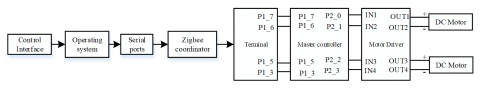
The circuit connection of the PC series port in the remotely controlled inspection vehicle is shown in Fig. 4.The ZigBee coordinator module receives control information from the upper computer through the series port. A 5V DC power supply is connected to the power ports of the ZigBee terminal module and the motor driver. The P1_7, P1_6, P1_5, and P1_3 ports of the ZigBee terminal nodes are connected to the P1_7, P1_6, P1_5, and P1_3 ports of the master control panel of the vehicle, and the P2_0, P2_1, P2_2, and P2_3 ports of the master control panel are connected to the IN1, IN2, IN3, and IN4 ports of the motor drivers, respectively.The four I/O output ports of the driver are connected to the “+” and “-” of the two DC motors.
Figure 2. Serial port remote controlcircuit connection
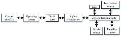
The circuit connection of the signal acquisition center is shown in Fig. 3. The DS18B20 used to measure temperature is a single-bus device. The middle pin is connected to a 4.7k pull-up resistor and the P1-1of the CC2530, and the P9 and P1_5 ports of the CC2530 are connected to the gas sensor and photosensitive sensor, respectively. The AOUT port of the gas sensor is connected to the P0_7 port of the CC2530, the serial port gyroscope is connected to the serial port of the CC2530, the I/O at the RX end is connected to the P0_2 port of the ZigBee module, and the I/O at the TX end is connected to the P0_3 port of the ZigBee module. The VCC of theDS18B20 is connected to aVC3.3V power supply, and those of other sensors are connected to a VC5V power supply.
Figure 3. The circuit connection of signal acquisition
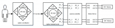
The circuit connection of the vehicle’s remote control center is shown in Fig. 4. There are five buttons on the CC2530 coordinator: UP, DN, LT, RT, and PUSH which can be pressed to make the vehicle move forward, move backward, turn left, turn right, and stop.
The power ports of the ZigBee coordinator, ZigBee terminal nodes, and DC motor driver are connected to a 5V DC power supply. The P1_7, P1_6, P1_5, and P1_3 of the ZigBee terminal nodes are connected to the P1_7, P1_6, P1_5, and P1_3 of the vehicle’s master controller, and the P2_0, P2_1, P2_2, and P2_3 of the master controller are connected to the IN1, IN2, IN3, and IN4 of the DC motor driver, respectively. The OUT1, OUT2, OUT3, and OUT4 of the driver are connected to the positive and negative electrodes of the two DC motors.
Figure 4. Remote control circuit connection
The system software includes the motor program of the inspection vehicle, the ZigBee wireless communication node program, and upper computer interface. The codes of the vehicle motor program were edited in Keil μVision4 software. The ZigBee wireless communication node program was developed based on the ZigBee2007/PRO protocol stack ZStack-2.0.0-1.2.0. The IAR Embedded WorkbenchV7.30B for 8051(IAR EW8051) was used to design the software, and the interface was built in Visual Studio 2010.
4.1 Basic movement subprogram of the inspection vehicle
The inspection vehicle remote control subprogram includes the basic movements of the vehicle and state management of the ZigBee terminal. If the ZigBee coordinator receives button information or a PC serial port control order, it conducts state management on the specified ZigBee terminal and sends the relevant signal to the ZigBee terminal nodes. The nodes send processed information to the master controller of the inspection vehicle, then drive the DC motor to make the vehicle move [2, 3, 9, 10].
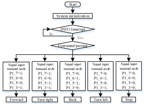
The inspection vehicle has four wheels which are controlled by four DC motors. Its speed is regulated under the PWM method [11]. Each motor needs three control signals: EN1, IN1, and IN2. EN1 is an enable signal, and IN1 and IN2 control the rotation direction of the motor. One PWM signal connects to the EN1 pin; when the IN1 and IN2 are 1 and 0, respectively, the motor rotates positively (and vice versa).Through different rotation direction and speed adjustments, the four motors realize forward, backward, left-turn, and right-turn motions of the inspection vehicle. The concrete control program flow is shown in Fig. 5. P1_7, P1_6, P1_5, and P1_3 are input signals of the single-chip microcomputer IO.
Figure 5. Program flow of inspection vehicle’s basic movements
4.2 Subprogram for remote control ofthe inspection vehicle
A flow chart of the coordinator subprogram remotely controlled by the inspection vehicle is shown in Fig. 6[10-13].
Head files declaration:
#include "OSAL.h"
#include "AF.h"
#include "ZDApp.h"
#include "ZDObject.h"
#include "ZDProfile.h"
#include <string.h>
#include "Coordinator.h"
#include "DebugTrace.h"
#if !defined(WIN32)
#include "OnBoard.h"
#endif
#include "hal_lcd.h"
#include "hal_led.h"
#include "hal_key.h"
#include "hal_uart.h"
Macro definition:
const cId_t GenericApp_ClusterList
[GENERICAPP_MAX_CLUSTERS]={ }
Device descriptor:
const SimpleDescriptionFormat_t GenericApp_SimpleDesc={}
Variable definition:
endPointDesc_t GenericApp_epDesc;
byte GenericApp_TaskID;
byte GenericApp_TransID;
void GenericApp_HandleKeys
(byte shift,byte keys );
Task initialization:
void GenericApp_Init(byte task_id){ }
Task processing function:
UINT16 GenericApp_ProcessEvent
(byte task_id,UINT16 events ){ }
Button processing subfunction:
static void GenericApp_HandleKeys( uint8 shift, uint8 keys ){ }
h file of ZigBee coordinator:
#ifndef COORDINATOR_H
#define COORDINATOR_H
#include"ZComDef.h"
#define GENERICAPP_ENDPOINT 10
#define GENERICAPP_PROFID 0x0F04
#define GENERICAPP_DEVICEID 0X0001
#define GENERICAPP_DEVICE_VERSION 0
#define GENERICAPP_FLAGS 0
#define GENERICAPP_MAX_CLUSTERS 1
#define GENERICAPP_CLUSTERID 1
extern void GenericApp_Init(byte task_id);
extern UINT16 GenericApp_ProcessEvent(byte task_id,UINT16 events);
#endif
Figure 6. Coordinator program flow of remotely controlled inspection vehicle
A control flow chart of the terminal node software remotely controlled by the inspection vehicle buttons is shown in Fig. 7.The head files declaration, macro definition, device descriptor, and task initialization subfunctions are the same as relevant subfunctions in the coordinator software design remotely controlled by the buttons, so they are not repeated here.
Variable definition subfunction:
endPointDesc_t GenericApp_epDesc;
byte GenericApp_TaskID;
byte GenericApp_TransID;
void GenericApp_MessageMSGCB
(afIncomingMSGPacket_t*pckt);
afAddrType_t my_DstAddr;
Task processing subfunction:
UINT16 GenericApp_ProcessEvent
(byte task_id,UINT16 events ){ }
void GenericApp_MessageMSGCB
(afIncomingMSGPacket_t *pkt){ }
Figure 7. Terminal nodesoftware program flowof remotely controlled inspection vehicle
The program flow of the remotely controlled master controller is shown in Fig. 8.This part of the system is mainly responsible for the basic movement functions of the inspection vehicle.
Figure 8. Master controller software program flow of remotely controlled inspection vehicle
4.3 Environmental parameter acquisition program
The sensor measures the temperature, light intensity, and humidity of the environment as well as movement data of the vehicle itself, then sends the information to the ZigBee terminal nodes. After processing, the information is sent to the ZigBee coordinator wirelessly [9], then to the computer through the serial port, where it is displayed.
The program flow of the ZigBee coordinator for environmental parameter acquisition is shown in Fig. 9.The codes, head files declaration, macro definition, device descriptor and task initialization code subfunction [10-12] of the inspection vehicle are the same as the program controlled by buttons.
The following variable definition was added:
static void rxCB(uint8 port,uint8 event);
static uint8 SerialApp_Buf[SERIAL_APP_TX_MAX];
Figure 9. Coordinator software program flow for environmental parameter acquisition
Structure function:
typedef union w{ } TEMPERATURE;
typedef union y{ }SHIDU;
typedef union g{ }GUANGQIANG;
The task processing function has added:
void GenericApp_MessageMSGCB
(afIncomingMSGPacket_t *pkt){ }
Serial port function:
static void rxCB(uint8 port,uint8 event){ }
The ZigBee terminal node program flow of environmental parameter acquisition is shown in Fig. 10.The head files declaration, macro definition, and device descriptor subfunction are consistent with corresponding subfunctions in the ZigBee terminal node program controlled by there mote buttons [10-13].
On the basis of the remotely controlled terminal node program, the following variable definition was added:
void GenericApp_Send_wd_Message(void);
void GenericApp_Send_gq_Message(void);
void GenericApp_Send_sd_Message(void);
void rxCB(uint8 port,uint8 event);
static uint8 SerialApp_Buf[SERIAL_APP_TX_MAX];
static uint8 SerialApp_Len;
uint16 myApp_ReadLightLevel( void );
uint16 myApp_ReadGasLevel( void );
int8 readTemp(void);
uint16 LightLevel;
afAddrType_t my_DstAddr;
Structure function:
typedef union w{ } TEMPERATURE;
typedef union s{ }YANWU;
typedef union g{ }GUANGQIANG;
On the basis of button control, task initialization includesthe serial port initialization function and wireless information transmission modes of the terminal nodes.
The task processing function would judge the scanned event, and call for scanned executable event function:
UINT16 GenericApp_ProcessEvent(byte task_id,UINT16 events ){ }
After acquiring information from the sensor, the corresponding values are calculated and sent to the program of the coordinator:
void GenericApp_Send_wd_Message(void){ }
void GenericApp_Send_sd_Message(void){ }
void GenericApp_Send_gq_Message(void){ }
Serial communication subfunction:
static void rxCB(uint8 port,uint8 event)
Figure 10. Terminal node program flow of environmental parameter acquisition
Based on the codes of coordinator h.file of the button-controlled inspection vehicle, the ZigBee coordinator h.file acquired via environmental parameters was added [13]:
#define GENERICAPP_wd_CLUSTERID2
#define GENERICAPP_sd_CLUSTERID 3
#define GENERICAPP_gq_CLUSTERID4
#define GENERICAPP_aj_CLUSTERID5
#define GENERICAPP_ck_CLUSTERID 6
#define GENERICAPP_jjsd_CLUSTERID 7
#define GENERICAPP_jsd_CLUSTERID 8
#define GENERICAPP_jd_CLUSTERID 9
#define SEND_DATA_EVENT 0x0001
#if !defined( SERIAL_APP_TX_MAX )
#define SERIAL_APP_TX_MAX 11
#endif
4.4 Program design ofserial port remotely controlled inspection vehicle
At the PC operation interface, the user presses the button to send serial port information to the ZigBee coordinator which then analyzes the serial port information and wirelessly sends corresponding information to the ZigBee terminal nodes. After being processed by the terminal nodes, the data is sent to the master controller of the inspection vehicle, then the vehicle moves accordingly.
The program flow of the ZigBee coordinator of the inspection vehicle is shown in Fig. 11.The head file declaration, macro definition, device descriptor, task initialization, and task processing subfunctions [10-12] are consistent with the subprograms of the ZigBee coordinator program of the remotely controlled inspection vehicle.
Figure 11. Coordinator software program flow of inspection vehicle remotely controlled via serial port
Variable definition:
static void rxCB(uint8 port,uint8 event);
Serial port function:
static void rxCB(uint8 port,uint8 event){ }
The program flow of the ZigBee terminal nodes of theremotely controlled inspection vehicle is shown in Fig. 12.The head file declaration, macro definition, device descriptor, variable definition, and task initialization subfunctions are consistent with corresponding subfunctions in the ZigBee terminal nodes of the button-controlled vehicle. Based on the subfunctions in the ZigBee terminal nodes, the task processing subfunction was given a code function controlled via serial port [10-13].
On the basis of the .h file of the vehicle’s coordinator, the ZigBee coordinator .h file of the vehicle was added as follows:
#define GENERICAPP_ck_CLUSTERID 6
Figure 12. Terminal node program flow ofinspection vehicle remotely controlled via serial port
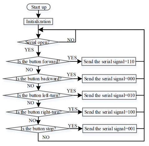
4.5 Upper computer software for remotely controlled inspection vehicle
The serial-port-controlled inspection vehicle interface, as built in Visual Studio 2010, is used to inspect button information and send it to the ZigBee coordinator through the serial port, then to the ZigBee terminal nodes. After receiving task data, the terminal nodes send it to the master controller to control the vehicle’s movement. The program flow of the vehicle remotely controlled via serial port is shown in Fig. 13.
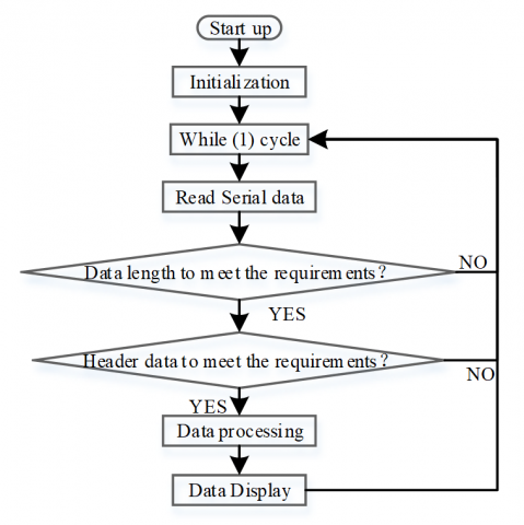
The environmental parameters acquired by the ZigBee terminal nodes, after being wirelessly sent to the coordinator, are written into the serial port. The data is processed in the upper computer software and displayed on the console in terms of certain norms and frequency [2, 3, 10, 12]. The program flow of the data acquisition center of the upper computer display interface is shown in Fig. 14.
Figure 13. Program flow of upper computer software of remotely controlled inspection vehicle
Figure 14. PC software program flow for data acquisition and display
In this study, we designed a greenhouse environment inspection control system based on ZigBee. The proposed system could be utilized in small greenhouses and laboratory greenhouses to allow remote inspection of the environmental information without necessitating that wireless sensor networks be established. The system is altogether quite economic and practical.
This research is supported by Water Science and Technology Project of Shaanxi Province in China (No. 2015slkj-11); Teaching reform project of Northwest A&F University (No. JY1302053); Students’ Innovative Research Plan of Northwest A&F University (1201510712120).
[1] J. Ma, L. Lin and X. Liu, “A fuzzy comprehensive evaluation of the applicability of intelligent greenhouse control systems,” Sensor Letters, vol. 11, no. 6, pp. 1396-1402, 2013.
[2] D.H. Park, B.J. Kang and K.R. Cho, “A Study on greenhouse automatic control system based on wireless sensor network,” Wireless Personal Communications, vol. 56, no. 1, pp. 117-130, 2011.
[3] J. Lin, Li Kong and F. Wang, “Wireless sensor network-based viticulture environmental monitoring system,” Journal of Drainage and Irrigation Machinery Engineering, vol. 32, no. 7, pp. 637-644, 2014. (in Chinese with English abstract)
[4] S. Park, M. Choi and B. Kang, “Design and implementation of smart energy management system for reducing power consumption using ZigBee wireless communication module,” Procedia Computer Science, vol. 19, pp. 662-668, 2013.
[5] Q. Zhang, X. Yang and Y. Zhou, “A wireless solution for greenhouse monitoring and control system based on ZigBee technology,” Journal of Zhejiang University: Science A, vol. 8, no. 10, pp. 1584-1587, 2007.
[6] W. Yang, K. Lv and M. Li, “The wireless intelligent controller of greenhouse based on zigbee,” Sensor Letters, vol. 11, no. 6, pp. 1321-1325, 2013.
[7] L. Gao, M. Cheng and J. Tang, “A wireless greenhouse monitoring system based on solar energy,” Telkomnika - Indonesian Journal of Electrical Engineering, vol. 11, no. 9, pp. 5448-5454, 2013.
[8] F. Shariff, N.A. Rahim and W.P. Hew, “Zigbee-based data acquisition system for online monitoring of grid-connected photovoltaic system,” Expert Systems with Applications, vol. 42, no. 3, pp. 1730–1742, 2015.
[9] X. Yan, “The design and research of greenhouse environmental monitoring system based on wireless network,” International Journal of Applied Environmental Sciences, vol. 8, no. 13, pp. 1737-1746, 2013.
[10] H. Luo, P. Yang and Y. Li, “An intelligent controlling system for greenhouse environment based on the architecture of the internet of things,” Sensor Letters, vol. 10, no. 1, pp. 514-522, 2012.
[11] T. Li, M. Zhang and Y. Ji, “Management of CO2 in a tomato greenhouse using WSN and BPNN techniques,” International Journal of Agricultural and Biological Engineering, vol. 8, no. 4, pp. 43-51, 2015.
[12] X. Li, X. Cheng and K. Yan, “A monitoring system for vegetable greenhouses based on a wireless sensor network,” Sensors (Switzerland), vol. 10, no. 10, pp. 8963-8980, 2010.
[13] D.H. Park, B.J. Kang and K.R. Cho, “A study on greenhouse automatic control system based on wireless sensor network,” Wireless Personal Communications, vol. 56, no. 1, pp. 117-130, 2011.