OPEN ACCESS
Aiming at overcoming the shortcomings of existing fatigue analysis methods in the calculation of gear, a new technique of precise modeling and fatigue analysis for spur gears is proposed based on machining principle. The spur gear tooth profile equations are derived from the blade profile equations based on plane engagement theory. According to the geometric relationship,a precise assembly model of the gear pair is established, then transient analysis has been done during its working process to find the maximum stress positions. In these positions, fatigue analyses are done to get gears’ safety factors. Compared with the conventional model, the results showing that the precise model has a higher strength, the conventional model and traditional gear design method are conservative.
Plane engagement principle, Precise model, The maximum stress position, Fatigue analysis
Fatigue failure is the main form of gear failure. Tooth surface pitting reduces transmission performance and increases operating noise. Tooth fracture will cause more serious consequences. So, gear as a key component of mechanical transmission, its fatigue life should be predicted and designed precisely.
Precise model is the basis of the subsequent analysis. Song Liwei [1] had established the conventional model in which the root transitional curve was replaced by arc, so the results of tooth root bending stress were inaccurate. Fu yongtao [2], Liu Lifang [3] only derived the root transitional curve equations but didn’t provide the boundary conditions, which would increase the difficulty of modeling while linking up with the adjacent tooth profiles. In the aspect of gear fatigue analysis: Wang Zhenghong [4] analyzed the bending fatigue life of gear in the maximum stress position, but the tooth transition line of the model was replaced by root arc, so that the analysis results were not meaningful. Wei Rui [5] applied linear distribution force at the pitch circle on a single tooth of planetary gear train, the gear tooth root bending fatigue life got in this way was irrational. Xue Yunfeng [6] analyzed fatigue life of planetary gear train with the two-dimensional model, “amplification factor” between the static analysis and dynamic analysis was proposed, but there was a big deviation in simplifying gear as plane strain problem which can’t take the uneven load distribution into account.
Based on planar meshing principle and the geometric relationship, the precise assembly model of spur gears has been established. The meshing process is simulated in ANSYS simulation environment, extracting the maximum stress positions [7~9] and doing fatigue analysis with Workbench fatigue module in their maximum stress positions, then the fatigue life and the safety factor of the gears are available.
According to plane engagement theory, the process that blade machines gear has been simulated. The gear tooth profile parametric equations have been deduced from the blade profile parameter equations. According to the tooth profile parametric equations, a simplified finite assembly element model of spur gears has been established. Each gear tooth profile section is represented by the equations.
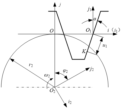
As shown in figure 1 to figure 3, So is fixed coordinate systems. Moveable coordinate systems So1 and So2 are rigidly connected to the gear and the blade of the generating machine, respectively. Initially, these three coordinate systems are coincident. So1 moves along x-axis. So2 revolves around z-axis.
According to plane engagement theory and the relative coordinate relations in figure 1, the equations of working part of the gear tooth can be expressed as formula 1. The parameters in the figure indicate the significance as follows: α is the blade profile angle; u1 indicates the signed distance from a point on the edge of the blade to the origin of the blade coordinate system; r2 is the pitch circle radius of gear; φ2 is the rotational angle of the gear; ω2 is the rotational speed of the gear.
Figure 1. Machining principle of working part of gear tooth
$\left. \begin{matrix} {{x}_{2}}={{u}_{1}}\sin \left( \alpha -{{\phi }_{2}} \right)+{{r}_{2}}\left( {{\phi }_{2}}\cos {{\phi }_{2}}-\sin {{\phi }_{2}} \right) \\ {{y}_{2}}={{u}_{1}}\cos \left( \alpha -{{\phi }_{2}} \right)+{{r}_{2}}\left( {{\phi }_{2}}\sin {{\phi }_{2}}+\cos {{\phi }_{2}} \right) \\ {{u}_{1}}+{{r}_{2}}{{\phi }_{2}}\sin \alpha =0 \\\end{matrix} \right\}$ (1)
Here:$-\frac{\left( {{h}_{1}}-{{r}_{0}}+{{r}_{0}}\sin \alpha \right)}{\cos \alpha }\le {{u}_{1}}\le \left( \sqrt{r_{2}^{2}+r_{a}^{2}}-{{r}_{2}}\sin \alpha \right)\tan \alpha $, ra is the tip circle radius of gear.
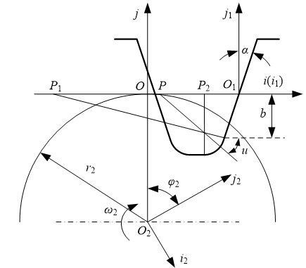
According to plane engagement theory and the relative coordinate relations in figure 2, the equations of the transitional curve can be obtained by equations 2 and equation 3. The new parameter in the figure indicates the significance as follows: u is the angel between x-axis and a line through point P and the fillet center, P can move from P1 to P2 , so the angle ranges from α to π/2.
Figure 2. Machining principle of transitional curve
$\left. \begin{matrix} {{x}_{2}}={{x}_{1}}\text{cos}{{\phi }_{2}}-{{y}_{1}}\sin {{\phi }_{2}}+{{r}_{2}}\left( {{\phi }_{2}}\cos {{\phi }_{2}}-\sin {{\phi }_{2}} \right) \\ {{y}_{2}}={{x}_{1}}\sin {{\phi }_{2}}+{{y}_{1}}\cos {{\phi }_{2}}+{{r}_{2}}\left( {{\phi }_{2}}\sin {{\phi }_{2}}+\cos {{\phi }_{2}} \right) \\ {{x}_{1}}=\left( {{r}_{0}}\cos u-{{r}_{0}}\cos \alpha -\left( {{h}_{1}}-{{r}_{0}}+{{r}_{0}}\sin \alpha \right)\tan \alpha \right) \\ {{y}_{1}}=\left( {{r}_{0}}-{{h}_{1}}-{{r}_{0}}\sin u \right) \\\end{matrix} \right\}$ (2)
$\left( {{r}_{2}}{{\phi }_{2}}-{{r}_{0}}\cos \alpha -\left( {{h}_{1}}-{{r}_{0}}+{{r}_{0}}\sin \alpha \right)\tan \alpha \right)\tan u-\left( {{h}_{1}}-{{r}_{0}} \right)=0$ (3)
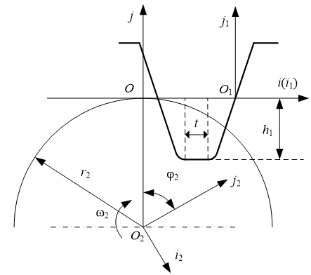
The equations of tooth root profile can be obtained according to plane engagement theory and the relative coordinate relations in figure 3, as shown in formula 4. t is blade top width.
Figure 3. Machining principle of tooth root profile
$\left. \begin{matrix} {{x}_{2}}=\text{x}\cos {{\phi }_{2}}+{{h}_{1}}\sin {{\phi }_{2}}+{{r}_{2}}\left( {{\phi }_{2}}\cos {{\phi }_{2}}-\sin {{\phi }_{2}} \right) \\ {{y}_{2}}=\text{x}s\text{in}{{\phi }_{2}}-{{h}_{1}}\cos {{\phi }_{2}}+{{r}_{2}}\left( {{\phi }_{2}}\sin {{\phi }_{2}}+\cos {{\phi }_{2}} \right) \\ {{r}_{2}}{{\phi }_{2}}=0 \\\end{matrix} \right\}$ (4)
Here:$H-\frac{t}{2}\le x\le H$, x represents the x-axis coordinate values, $H={{r}_{0}}(\tan \alpha -\cos \alpha )-\left( {{h}_{1}}+{{r}_{0}}\sin \alpha \right)\tan \alpha $.
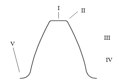
All of above equations constitute the tooth profiles. Additionally, tip circle is formed by blank naturally, as showed in figure 4 (line I). In order to avoid the appearance of severe contact stress, grinding is also needed to process tip fillet, as showed in figure 4 (line II). In this paper, the model has taken all above factors into account.
3.1 Simplified finite element model of the spur gears
Precise modeling of spur gears includes two aspects: precise modeling of single gear and precise assembly. The gear tooth profile has been built based on the tooth profile parameter equations, as shown in figure 4. Lines III, IV, V represent working part of gear tooth, transitional curve and tooth root profile respectively. These three parts are formed by the cutting tool.
Figure 4. Tooth profile of spur gear
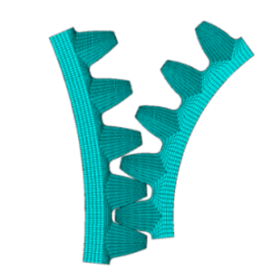
A simplified finite element assembly model has been established, as shown in figure 5.
Figure 5. Simplified finite element assembly model
3.2 Transient meshing analysis of spur gears
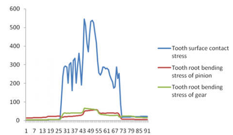
As for a pair of gears, their bending and contact stresses are pulsating cycle. The extreme stresses that the gears suffered contribute to the value of fatigue life. The maximum stress positions have been obtained by transient analysis, including the maximum tooth root bending stress positions and the maximum tooth surface contact stress position of pinion and gear. Because of the engaging line characteristics of spur gears, transient meshing analysis can be done by slices to reduce computation time.
After doing transient meshing analysis towards the slice model, stress curves can be obtained by reading results. As shown in figure 6, the three ultimate stress positions vary. By reading the load step number corresponding to the ultimate position, the angle between the ultimate position and the initial position can be available to establish the engagement model at corresponding positions.
Figure 6. Stress curves of gears transient meshing analysis
The way that section titles and other headings are displayed in these instructions, is meant to be followed in your paper.
Because the function of workbench in modeling and meshing is less powerful than ANSYS, therefore it’s better to establish model in ANSYS first, then import it to the workbench.
Two necessary conditions for fatigue analysis are material properties and load spectra. Material properties are acquired by experimental test and load spectra are obtained by static analysis. Pinion material is 40Cr (Quenched and tempered) and gear material is 45 steel (Quenched and tempered), their elasticity modulus E are 0.211Gpa, 0.209Gpa, their Poisson's ratio v are 0.277, 0.269. Based on the figures of bending and contact fatigue life factor in the failure probability of 1%, some suitable points can be found from the figures. As for high cycle stress fatigue, the fatigue model used is three-parameter power function model [10], the equation is as follows:
$\log {{N}_{f}}={{A}_{1}}+{{A}_{2}}\log ({{S}_{eq}}-{{A}_{3}})$ (5)
Here: Nf is cycle life; Seq is equivalent stress; A1, A2, A3 are undetermined Coefficients.
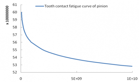
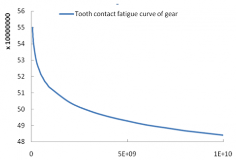
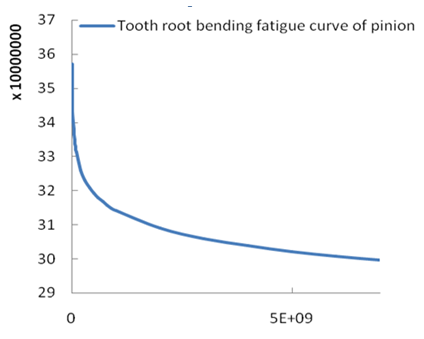
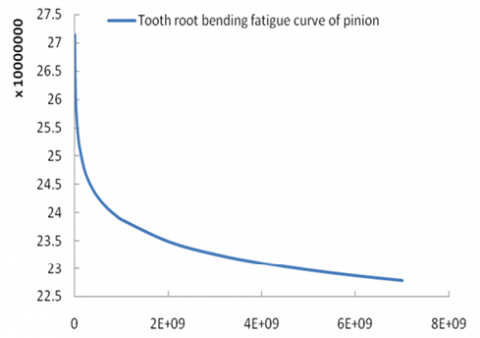
Substituting the points into above equation, bending and contact fatigue S-N curves of pinion and gear can be drawn out, as shown below:
Figure 7. Tooth contact fatigue life curve of pinion
Figure 8. Tooth contact fatigue life curve of gear
Figure 9. Tooth root bending fatigue life curve of pinion
Figure 10. Tooth root bending fatigue life curve of gear
In static analysis system, the driving gear is applied fixed constraint and the driven gear is applied load torque.
The next step is inserting fatigue tool after static analysis, solving and setting the corresponding parameters. By comparing the results of the dynamics and statics analysis, an amplification factor K1 (1.5~1.8) is required in static analysis to simulate the working status of the gear better, this article takes 1.5. Since workbench can only identify the equivalent stress in fatigue analysis, another amplification factor K2 will be needed to enlarge the equivalent stress to the contact stress for contact fatigue analysis.
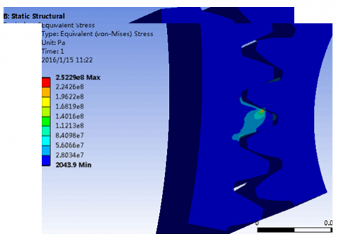
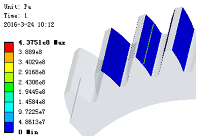
The equivalent stress cloud or pressure cloud of gears can be obtained after solving, as follows:
Figure 11. The equivalent stress cloud
Figure 12. The equivalent pressure cloud
The following figure is a contact safety factor cloud.
Figure 13. Contact fatigue safety factors cloud
To verifying the rationality and effectiveness of the proposed method, the analysis results of two kinds of models in same method have been contrasted. In this example, the speed of driving gear n1 is 960r / min, input power P1 is 10KW, the design life is 15 years. Gears structural parameters corresponding to the two different models are shown in Table 1 and Table 2.
Table 1. The gears’ parameters of processing model
|
|
pinion |
wheel |
|
Number of gear teeth |
31 |
99 |
|
Modulus m (mm) |
2 |
2 |
|
Blade tip fillet radius(mm) |
0.3m |
0.3m |
|
Tooth width (mm) |
70 |
65 |
|
Modification coefficient |
0.502 |
0.503 |
|
|
pinion |
wheel |
|
Number of gear teeth |
31 |
99 |
|
Modulus m (mm) |
2 |
2 |
|
Tooth root fillet radius(mm) |
0.38m |
0.38m |
|
Tooth width (mm) |
70 |
65 |
|
Modification coefficient |
0.502 |
0.503 |
The results of traditional design methods for calculating safety factor are as follows: Contact fatigue safety factor is 1.0215; pinion tooth root bending fatigue safety factor is 2.64, gear tooth root bending fatigue safety factor is 2.04.
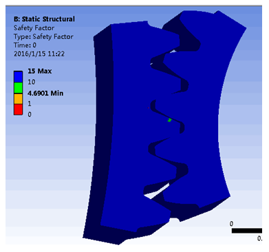
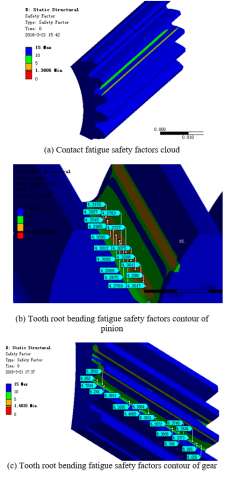
The safety factor contours obtained from the conventional model are shown as follows:
Figure 14. Safety factors clouds of the conventional model
From the figure 14, the results of the conventional model are available as follows: the tooth surface contact fatigue safety factor is 1.3806, pinion tooth root bending fatigue safety factor is about 4.2, gear tooth root bending fatigue safety factor is about 6.
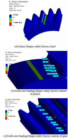
It can be read from the figures 15 that, the results of processing model are as follows: the tooth surface contact fatigue safety factor is 1.5086, pinion tooth root bending fatigue safety factor is about 11.5, gear tooth root bending fatigue safety factor is about 13.
The safety factor contours obtained from processing model are shown as follows:
Figure 15. Safety factors clouds of the processing model
By comparison: the safety factors got in conventional gear design method have greater redundancy. The results obtained by the two modeling methods show that the processing model has a larger safety factor, especially in the part of the tooth root.
Based on plane engagement theory and the blade profile equations, the spur gear tooth profile equations are derived. On this basis, the precise assembly model of gears is achieved. The meshing process is simulated in ANSYS simulation environment, extracting the maximum stress positions and doing fatigue analysis with Workbench fatigue module in the positions, then the value of fatigue life and safety factor of the gears are obtained. Through the fatigue analysis results in corresponding positions, gear life and safety factor can be read directly. The results obtained by the two modeling methods show that the processing model has a larger safety factor, especially in the part of the tooth root.
This work is supported by the National Natural Science Foundation of China (Grant No.51375282), the Special Funds for Cultivation of Taishan Scholars, the Shandong Provincial Natural Science Foundation of China (Grant No.ZR2015EM017 & ZR2014EEM021), the Science and Technology Development Program of Shandong Province (Grant No.2014GGX103043), and the Innovation Foundation for Graduate Students of Shandong University of Science and Technology (Grant No.YC150211).
[1] Song Liwei, Li Fengfeng and Zheng tianhu, “The strength of spur gear based on Pro/e and ABAQUS,” Mechanical Research & Applications, vol. 27, no. 4, pp.68-70, 2014 (in Chinese).
[2] Fu Yongtao, Gu Lichen, Li Liang, et al., “Parametric Modeling of displacement helical gear based on UG redevelopment,” Mechanical transmission, vol. 38, no. 1, pp.62-66, 2014 (in Chinese).
[3] Liu Lifang, “Helical gear modeling and stress analysis,” M.S. thesis, Northeastern Univ., Shenyang, CHN, 2012.
[4] Wang Hongzheng, “Bending fatigue life analysis of helical gear reducer in horizontal shaft boring machine,” Value Engineering, vol. 31, no. 23, pp. 43-45, 2012 (in Chinese).
[5] Wei Rui, Xie Feng, Shao Shichao, et al., “Fatigue life prediction of Benz bridge wheel reducer,” Machinery, vol. 39, no. 11, pp. 1-4, 2012 (in Chinese).
[6] Xue Yunfeng, Wang Jiaming, He Qichang, et al., “Fatigue analysis of large tub reducer gear system,” Computer Aided Engineering, vol. 23, no. 1, pp. 16-20, 2014 (in Chinese).
[7] Li X., Li C., Li S., et al., “Contact dynamics analysis of helical gear based on precise tooth surface model,” International Review on Computers and Software, vol. 7, no. 3, 2012.
[8] Li X., Li C., Geng D., et al., “Accurate numerical analysis of gear strength based on finite element method,” Journal of Theoretical and Applied Information Technology, vol. 46, no. 2, 2012.
[9] Li Xueyi, Li Sanshuai and Zeng Qingliang, “Study on the strength of mine carburized gears reducer based on dynamics,” Journal of China Coal Society, vol. 36, no. 7, pp.1127-1231, 2011.
[10] Li Chi, Zhang Guodong, Xu Chao, et al., “Research on fatigue S-N curves of high cycle stress,” Gas Turbine Experiment and Research, no. 2, pp. 39-43, 2008.