OPEN ACCESS
The aim of this study is to numerically examine the improvement techniques of the heat transfer in inclined tubes. The passive enhancement techniques are some of the most important means to improve heat transfer rates in engineering devices. In this research a passive enhancement technique (vortex generation) is combined with the tube inclination in order to improve heat transfer rates in solar concentrator absorber. Fins, acting as vortex generators, were attached to the internal wall of the tubes at different positions. A numerical simulation was performed using fluent software in which the finite volume method was used to solve the governing equations. The heat transfer rates obtained numerically were compared to those calculated using well known correlation (i.e. correlation of Shah and London) or others obtained experimentally. Through this study, it was found that the influence of fins on heat transfer rates is more important for the laminar regime than for the turbulent one for all considered inclinations. The optimal inclinations, which allow increasing the heat transfer, have also been determined for both laminar and turbulent flows. The findings of this research can be used to improve the heat transfer rates and therefore the efficiency of the solar concentrator absorber.
heat transfer improvement, passive techniques, solar concentrator absorber, forced convection, heat transfer rate, numerical simulation
The engineering devices thermal performances remain limited due to the low thermal conductivities of classical working fluids. The heat transfer enhancement in the solar concentrator absorber can reduces the energy requirement as well as tube material and cost saving. However, heat transfer can be improved by modifying the flow behavior, the boundary conditions or by acting on the fluid thermo-physical properties. In order to improve thermal performances of engineering equipments, several heat transfer enhancement techniques have been used in the literature. Passive enhancement methods, that use surface or geometrical modifications by incorporating inserts or additional devices [1], are considered to be some of the most important means to enhance heat transfer in heat exchange devices that allow also reducing their size and manufacturing cost [2]. Therefore, several studies have been devoted to heat transfer enhancement techniques [3-7]. The inclinations of tubes, the use of an external magnetic field, the attachment of fins or the use of other heat transfer fluids, such as nanofluids [8] , supercritical CO2 or refrigerants, affect in a significant way the characteristics and behavior of the flow and can improve heat transfer rates. Many studies have been devoted to the heat transfer in horizontal, vertical tubes or those with inclinations. For example, authors in [9] studied numerically the characteristics of convective heat transfer of supercritical CO2 in a circular horizontal tube with low Reynolds numbers (between 210 and 1800). The results show that an increase of Nusselt number has been obtained with a Reynolds number of 210. Several experimental studies [10-11] have been conducted concerning heat transfer and pressure drop characteristics of supercritical CO2 inside horizontal or inclined tubes. An empirical correlation has been proposed and it has been found that Gnielinski correlation predicts accurately the heat transfer coefficient. In [12], an experimental study has been carried out of the evaporating two-phase heat transfer of refrigerants in a smooth tube with various inclinations. The tube inclination effects on heat transfer coefficient have been considered by several researchers and an optimal inclination has been determined. Kundu et al. [13] presented the results of an experimental study of the evaporation of R407C refrigerant inside a smooth tube with various inclinations. An empirical correlation has been developed to predict the heat transfer coefficient during the evaporation of R407C inside the inclined tube. In [14], an experimental study has been carried out in a stainless steel tube using the R134a refrigerant at supercritical pressures and for various mass velocities. The experimental heat transfer coefficient and pressure drop have been compared to Petrov and Popov and Gnielinski correlations and a good agreement has been achieved. Orfi et al. [15] studied numerically the heat transfer and fluid flow of an incompressible fluid in inclined circular tube. They compared the obtained results to those of the horizontal case. The results show an improvement of the average heat transfer coefficient compared to an only forced convective flow. In [16], the components of axial and radial velocities for the mixed convention of water in an isothermal inclined tube have been measured using the PIV technique. The results showed that the inclinations of the tube have an impact on the flow behavior.
This paper investigates numerically the single phase heat transfer and fluid flow in a tube for various inclinations combined with fins used as vortex generators, with the aim to improve the heat transfer in tube receivers used in solar collectors. For that purpose, different tube inclinations are studied and combined with different fin positions in order to find the optimum configuration, which allows obtaining the highest heat transfer rates.
The remainder of this paper is organized as follows: Section 2 introduces the governing equations of the problem with the appropriate boundary conditions, Section 3 describes the numerical simulation procedure and Section 4 discusses the obtained results.
A numerical model of two dimensional, steady state and incompressible fluid flow and heat transfer through tubes is developed based on mass, momentum, and energy conservation equations as flows:
$\frac{\partial \rho {{u}_{1}}}{\partial x}+\frac{\partial \rho {{u}_{2}}}{\partial y}+\frac{\partial \rho {{u}_{3}}}{\partial z}=0$ (1)
$\sum\limits_{j=1}^{3}{\frac{\partial (\rho {{u}_{i}}{{u}_{j}})}{\partial {{x}_{j}}}}=-\frac{\partial p}{\partial {{x}_{i}}}+\sum\limits_{j=1}^{3}{\frac{\partial }{\partial {{x}_{j}}}\left[ \mu \left( \frac{\partial {{u}_{i}}}{\partial {{x}_{j}}}+\frac{\partial {{u}_{j}}}{\partial {{x}_{i}}}-\frac{2}{3}{{\delta }_{ij}}\sum\limits_{i=1}^{3}{\frac{\partial {{u}_{i}}}{\partial {{x}_{i}}}} \right) \right]}$ (2)
$\sum\limits_{j=1}^{3}{\frac{\partial (\rho E{{u}_{j}})}{\partial {{x}_{j}}}}=\sum\limits_{i=1}^{3}{{}}\sum\limits_{j=1}^{3}{\left( \frac{\partial }{\partial {{x}_{j}}}({{\tau }_{ij}}){{u}_{i}} \right)-\sum\limits_{j=1}^{3}{\frac{\partial }{\partial {{x}_{j}}}{{q}_{j}}}}$ (3)
The physical properties of the fluid are assumed to be constant.
For the considered configuration, the boundary conditions are given by:
$\frac{\partial T}{\partial y}=0, \frac{\partial P}{\partial y}=0, \frac{\partial u}{\partial y}=0$
$\left\{ \begin{align} & {{T}_{f}}(x,t)={{T}_{s}}(x,t) \\ & -{{\lambda }_{f}}\left( \frac{\partial {{T}_{f}}(x,t)}{\partial y} \right)=-{{\lambda }_{s}}\left( \frac{\partial {{T}_{s}}(x,t)}{\partial y} \right) \\\end{align} \right.$ (4)
The average convective heat transfer coefficient and the average Nusselt number are calculated as follows:
$h\,=\,\frac{1}{L}\int\limits_{0}^{L}{{{h}_{l}}dy}$ (5)
$Nu\,=\,\frac{1}{L}\int\limits_{0}^{L}{N{{u}_{l}}dy}$ (6)
With hl and Nul are respectively, the local convective heat transfer coefficient and the local Nusselt number. L is the tube length.
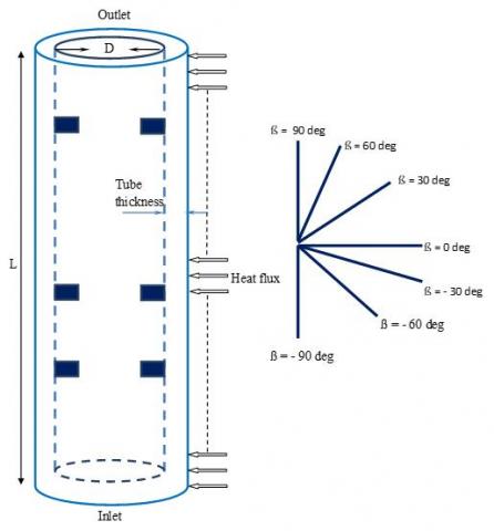
The studied tube has a 500 m length, an inner diameter of 10 mm and a 1 mm thickness. The fins are located at 50, 200 and 400 mm from the inlet of the tube (Figure 1). Various inclinations of the tube have been considered: (ß = 0, -30 deg, 30 deg, -60 deg, 60 deg, -90 deg and 90 deg). Fluent software, which is based on the finite volume method, was used to solve the governing equations. SIMPLE algorithm was chosen for the resolution of the pressure-velocity coupling with the RNG k-ε for turbulence modeling. The conjugated heat transfer conditions at the fluid-solid interface have also been considered. The importance of such coupling conditions has been stressed out by several researchers [17-20], particularly for transient regimes corresponding to operating conditions such as startup, shutoff, or any change in the operating conditions of many applications such as heat exchangers [2].
Figure 1. Geometry of the studied tube
3.1 Grid independence study
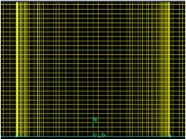
In order to choose the most appropriate mesh, a grid independence study was conducted. The independence on mesh size is evaluated through low variation of average heat transfer coefficients. For that purpose, five different meshes have been tested; their details are mentioned in Table 1. Heat transfer coefficients calculated using the numerical procedure and corresponding to each chosen mesh are also shown in Table 1. It is clear that from the third mesh (Mesh 3), the value of the convective heat transfer coefficient remains constant. Therefore, Mesh 1 and Mesh 2 are not suitable and Mesh 3 has been selected for this numerical study, because it gives the same results as Mesh 4 and Mesh 5 but with a small grid size. For the chosen mesh (Mesh 3) shown in Figure 2, a total number of 270,000 elements have been generated in the fluid zone and 30,000 elements in the solid zone
Table 1. Details of the different tested meshes and corresponding average heat transfer coefficients
|
Mesh |
Number of elements fluid zone |
Number of elements solid zone |
Average heat transfer rate W/m2.K |
|
Mesh 1 |
30,000 |
10,000 |
944.9524 |
|
Mesh 2 |
120,000 |
20,000 |
908.4986 |
|
Mesh 3 |
270,000 |
30,000 |
913.217 |
|
Mesh 4 |
300,000 |
35,000 |
913.216 |
|
Mesh 5 |
320,000 |
40,000 |
913.215 |
3.2 Validation of the numerical procedure
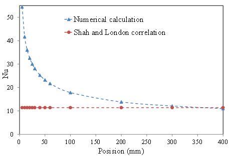
In order to validate the numerical procedure, the calculated Nusselt number in the tube using our numerical procedure has been compared to that obtained by other authors for similar conditions. Figure 3 shows the comparison of local Nusselt number obtained numerically for a vertical tube in a laminar regime with that obtained using Shah and London correlation [21]. The correlation of Shah and London is given as follows:
For the thermally developed region and a constant heat flux, the Nusselt number is given by (for Re.Pr.D/L ≥ 33.3 and Re < 2200):
$Nu=\,1.953\,{{(\operatorname{Re}.\Pr .\frac{D}{L})}^{0.33}}$ (7)
From Figure 3, it can be seen that for x ≥ 200, the two curves tend to the same value that corresponds to the well-established thermal flow.
Figure 3. Local Nusselt number calculated numerically, compared to that obtained by Shah and London correlation [21] for Re = 1500
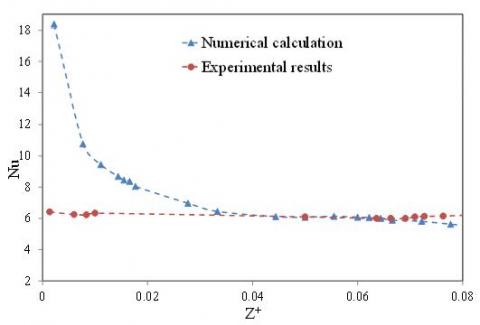
Another validation of the numerical simulation has also been carried out for the case of a horizontal tube. For that purpose, the calculated local Nusselt number in the horizontal tube using the numerical procedure has been compared to that obtained experimentally by [22]. In [22], an experimental work has been carried out in order to study the local and average thermal transfer rates for thermally developed laminar flow of air in a horizontal tube with various Reynolds numbers (between 400 and 1600). Figures 4 and 5 show the comparison of the Nusselt number obtained experimentally and the numerical ones as function of the dimensionless axial distance Z+ with a low thermal heat flux q = 92 W/m2 and various Reynolds number. Z+ being defined as follows:
${{Z}^{+}}=\,\frac{x}{D}\operatorname{Re}.\Pr$ (8)
It can be seen that for all Reynolds numbers, the Nusselt numbers obtained using the two approaches (experimental or numerical) are very close and have the same tendency
Figure 4. Local Nusselt number calculated numerically, compared to that obtained experimentally [22] for Re = 800
Figure 5. Local Nusselt number calculated numerically, compared to that obtained experimentally [22] for Re=1100
As a conclusion, our numerical procedure has been validated. Therefore, further parametric and detailed study can be performed.
4.1 Configuration without fins
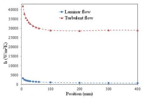
Before considering the inclined tubes and the attachment of fins, it is useful to analyze the results obtained for the reference case of a vertical tube without fins. Figure 6 shows the variation of a local heat transfer coefficient for both laminar and turbulent regimes. It can be clearly noticed that, as expected, the turbulent heat transfer coefficient is much greater than the laminar one.
Figure 6. Local heat transfer coefficient for a vertical tube without fins
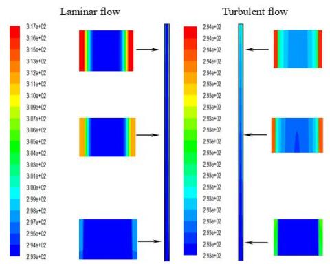
Figure 7 shows the temperature fields in a vertical tube for laminar and turbulent flows with Reynolds number of 1500 and 15,000 respectively.
Figure 7. Temperature fields in the vertical tube without fins
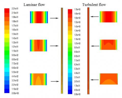
For both cases, the same heat flux was applied at the external tube wall. It can be noticed that the temperature difference between the wall and the fluid is very small at the tube inlet for both cases. This explains the high value of the heat transfer coefficient at this location. Beyond the inlet of the tube this temperature difference becomes larger, inducing thus a decrease of heat transfer coefficient values. The temperature distribution in the fluid zone is more homogeneous in the case of the turbulent flow, thus giving a better heat exchange between the wall and the fluid, which induces high values of turbulent heat transfer coefficient compared to the laminar one. The homogeneous temperature distribution of the turbulent regime is due to the better mixing of the flow in the tube when compared to the laminar regime, as shown in Figure 8.
Figure 8. Velocity contours in the vertical tube without fins
4.2 Configuration with fins
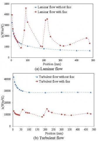
In order to explore heat transfer rates when inserting fins, the local heat transfer coefficient corresponding to the tube with fins has been compared to that without fins for both laminar and turbulent flows (Figure 9).
Figure 9. Local heat transfer coefficient in a vertical tube, with and without fins
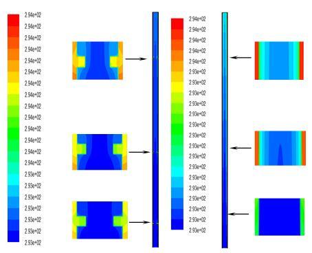
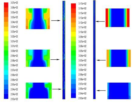
It can be clearly seen that the wall-fluid temperature gradient in the case of the tube with attached fins is larger than that corresponding to the tube without fins for the turbulent flow (Figure 10). However, for the laminar flow, the opposite behavior is observed (Figure 11). Since the local heat transfer coefficient is given by the wall heat flux divided by the wall-fluid temperature gradient, thus it increases when the wall-fluid temperature gradient decreases and vice versa.
Figure 10. Temperature fields in the vertical tube with and without fins, for the turbulent flow
Figure 11. Temperature fields in the vertical tube with and without fins, for the laminar flow
4.3 Inclined tubes
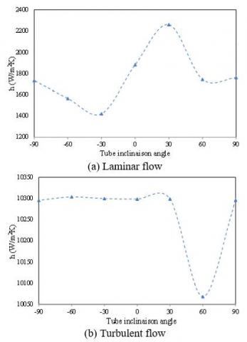
In order to investigate the effect of tube inclinations on heat transfer rates, some typical results are presented concerning the average heat transfer coefficient in the tube. Figure 12 shows the average heat transfer coefficient in the tube without fins for various inclinations for both laminar and turbulent flow. It can be noticed that the optimal inclination angle corresponding to the highest heat transfer coefficient is (- 60 degrees) for the turbulent flow and (90 degrees) for the laminar one.
Figure 13 shows the average heat transfer coefficient in the tube with fins for various inclinations for both laminar and turbulent flow. In that case, it can also be noticed that the optimal inclination angle is (- 60 degrees) for the turbulent flow but for the laminar one the optimal inclination angle is (30 degrees).
Figure 12. Average heat transfer coefficient at different inclinations for a tube without fins
Figure 13. Average heat transfer coefficient at different inclinations for a tube with fins
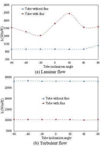
By comparing the results corresponding to the tube with attached fins to that without fins (Figure 14), it can be concluded that, as for the vertical tube, the heat transfer coefficient corresponding to the turbulent flow for the tube without fins is higher than that for the tube with fins for all inclinations. Unlike the laminar flow, for which the heat transfer coefficient in the tube with fins, is larger than that in the tube without fins for all inclinations. It can also be noticed that for the tube with attached fins, the heat transfer coefficient decreases when the inclination angle varies from - 90 to - 30 degrees, then it increases to reach its maximum value for ß = 30 and decreases subsequently. It can be concluded that the attachment of fins in the tubes is only useful for the laminar flow since it allows increasing heat transfer rates.
Figure 14. Average heat transfer coefficient in a tube with or without fins at different inclinations
Convective heat transfer of water for laminar or turbulent regimes in a tube with various inclinations has been studied. The developed numerical simulation procedure has been validated by comparing the obtained results with those of other authors. It has been noticed that convective heat transfer for a turbulent regime is larger than that for the laminar one for all inclinations. The attachment of fins allows increasing the rates of heat transfer for the laminar regime. For the turbulent regime, the fins reduce the heat transfer rates. Such results have been observed for all considered inclinations. The optimal angles which allow transferring the maximum of heat have also been determined. According to the calculations, it has been noticed that the best angle for the turbulent regime in inclined conducts with or without fins is (ß = - 60 deg.). According to the calculations, it has also been concluded that the best angle for the laminar regime in inclined conducts with fins is (ß = 30 deg.).
The numerical study conducted in this paper allowed concluding that it is possible to increase heat transfer rates in inclined tubes, used as receivers in solar collectors, by attaching fins which act as vortex generators in laminar convective flows.
For further research, we suggest studying the three-dimensional case with fins attached only at the bottom of the absorber of the solar concentrator where the solar heat flux is concentrated.
|
D |
diameter of the tube, m |
|
|
E |
energy, J |
|
|
h |
heat transfer coefficient, W.m-2. K-1 |
|
|
L |
length of the tube, m |
|
|
Nu |
Nusselt number, dimensionless |
|
|
P |
pressure, Bar |
|
|
Pr |
Pransdtl number, dimensionless |
|
|
q |
heat flux, W.m-2 |
|
|
Re |
Reynolds number, dimensionless |
|
|
T |
temperature, K |
|
|
u |
velocity, m.s-1 |
|
|
Z+ |
dimensionless axial distance |
|
|
Greek symbols |
|
|
|
b |
tube inclination angle, degrees |
|
|
λ |
thermal conductivity, W.m-1. K-1 |
|
|
µ |
dynamic viscosity, kg. m-1.s-1 |
|
|
ρ |
density, kg. m-3 |
|
|
Subscripts |
|
|
|
f |
fluid |
|
|
l |
local |
|
|
s |
solid |
|
[1] Liu, S., Sakar, M. (2013). A comprehensive review on passive heat transfer enhancements in pipe exchangers. Renewable and Sustainable Energy Reviews, 19: 64-81. https://doi.org/10.1016/j.rser.2012.11.021
[2] Mebarki, G., Rahal, S. (2016). Passive control of two-phase flow thermal instabilities in a vertical tube evaporator. Journal of Thermal Science and Engineering Applications, 8(4): 6 pages. https://doi.org/10.1115/1.4034092
[3] Ji, W., Jacobi, A., He, Y., Tao, W. (2015). Summary and evaluation on single-phase heat transfer enhancement techniques of liquid laminar and turbulent pipe flow. International Journal of Heat and Mass Transfer, 88: 735-754. https://doi.org/10.1016/j.ijheatmasstransfer.2015.04.008
[4] Kim, D., Yu, D., Jerng, D., Kim, M., Ahn, S. (2015). Review of boiling heat transfer enhancement on micro/nanostructured surfaces. Experimental Thermal and Fluid Science, 66: 173-196. https://doi.org/10.1016/j.expthermflusci.2015.03.023
[5] Bergles, A.E. (2011). Recent developments in enhanced heat transfer. Heat and Mass Transfer, 47(8): 1001-1008. https://doi.org/10.1007/s00231-011-0872-y
[6] Wang, X., Jiao, Y., Niu, Y., Yang J. (2015). Study on enhanced heat transfer features of nano-magnetic fluid heat pipe under magnetic field. International Journal of Heat and Technology, 33(1): 137-144. https://doi.org/10.18280/ijht.330119
[7] Suvanjan, B., Himadri, C., Alexander, S., Kamal, U. (2016). Convective heat transfer enhancement and entropy generation of laminar flow of water through a wavy channel. International Journal of Heat and Technology, 34(4): 727-733. https://doi.org/10.18280/ijht.340425
[8] Buonomo, B., Cascetta, F., Cirillo, L., Nardini, S. (2018). Application of nanofluids in solar cooling system: Dynamic simulation by means of TRNSYS software. Modelling, Measurement and Control B, 87(3): 143-150. https://doi.org/10.18280/mmc_b.870305
[9] Zhang, X.R., Yamaguchi, H. (2007). Forced convection heat transfer of supercritical CO2 in a horizontal circular tube. The Journal of Supercritical Fluids, 41(3): 412-420. https://doi.org/10.1016/j.supflu.2006.11.003
[10] Dang, C.B., Hihara, E. (2004). In-tube cooling of supercritical carbon dioxide. Part 1: experimental measurement. International Journal of Refrigeration, 27(7): 736-747. https://doi.org/10.1016/j.ijrefrig.2004.04.018
[11] Yang, C., Xu, J., Wang, X., Zhang, W. (2013). Mixed convective flow and heat transfer of supercritical CO2 in circular tubes at various inclination angles. International Journal of Heat and Mass Transfer, 64: 212-223. https://doi.org/10.1016/j.ijheatmasstransfer.2013.04.033
[12] Kundu, A., Kumar, R., Gupta, A. (2014). Evaporative heat transfer of R134a and R407c inside a smooth tube with different inclinations. International Journal of Heat and Mass Transfer, 76: 523-533. https://doi.org/10.1016/j.ijheatmasstransfer.2014.04.056
[13] Kundu, A., Kuman, R., Gupta, A. (2014). Flow boiling heat transfer characteristics of R407c inside a smooth tube with different inclinations. International Journal of Refrigeration, 45: 1-12. https://doi.org/10.1016/10.1016/j.ijrefrig.2014.06.009
[14] Zhao, C.R., Jiang, P.X. (2011). Experimental study of in-tube cooling heat transfer and pressure drop characteristics of R134a at supercritical pressures. Experimental Thermal and Fluid Science, 35(7): 1293-1303. https://doi.org/10.1016/j.expthermflusci.2011.04.017
[15] Orfi, J., Galanis, N., Nguyen, C.T. (1997). developpement simultane hydrodynamique et thermique d’un ecoulement laminaire dans un tube incline en regime de convection mixte. Revue Générale de Thermique, 36(2): 83-92. https://doi.org/10.1016/S0035-3159(99)80053-1
[16] Maré, T., Galanis, N., Voicu, I., Miriel, J. (2006). Experimental analysis of mixed convection in inclined tubes. Applied Thermal Engineering, 26(14-15): 1677-1683. https://doi.org/10.1016/j.applthermaleng.2005.11.011
[17] Ates, A., Darici, S., Bilir, S. (2010). Unsteady conjugated heat transfer in thick walled pipes involving two-dimensional wall and axial fluid conduction with uniform heat flux boundary condition. International Journal of Heat and Mass Transfer, 53(23-24): 5058-5064. https://doi.org/10.1016/j.ijheatmasstransfer.2010.07.059
[18] Du, S.Y., Zhao, Y.H. (2012). Numerical study of conjugated heat transfer in evaporating thin-films near the contact line. International Journal of Heat and Mass Transfer, 55(1-3): 61-68. https://doi.org/10.1016/j.ijheatmasstransfer.2011.08.039
[19] Mebarki, G., Rahal, S. (2013). Numerical simulation and control of two-phase flow with evaporation in a vertical tube submitted to a conjugate heat transfer. Journal of Energy and Power Engineering, 7(7): 1282-1292. https://doi.org/10.17265/1934-8975/2013.07.010
[20] Bahreini, M., Ramiar A., Ranjbar, A.A. (2017). Numerical simulation of subcooled flow boiling under conjugate heat transfer and microgravity condition in a vertical mini channel. Applied Thermal Engineering, 113: 170-185. https://doi.org/10.1016/j.applthermaleng.2016.11.016
[21] Shah, R.K., London, A.L. (1978). Laminar flow forced convection in ducts. Advances in Heat Transfer, Thomas I., James P.H. (Eds), Academic Press, Burlington.
[22] Mohammed, H.A., Salman, Y.K. (2007). Free and forced convection heat transfer in the thermal entry region for laminar flow inside a circular cylinder horizontally oriented. Energy Conversion and Management, 48(7): 2185-2995. https://doi.org/doi.org/10.1016/j.enconman.2006.12.016