Senthil Murugan S.* | Noorul Haq A. | Sathiya P.
© 2020 IIETA. This article is published by IIETA and is licensed under the CC BY 4.0 license (http://creativecommons.org/licenses/by/4.0/).
OPEN ACCESS
This study discusses the dissimilar joining between AA6063 aluminium and AISI304L stainless steel of flat faying surfaces through a rotary friction welding process at different welding conditions as per L9 orthogonal array and the characterization of bimetal joints. The effect of welding parameters on the mechanical properties and the minimum level of welding conditions required for the metals joining were discussed. Bonding between the metals and the narrow heat-affected zone were observed from microscopy study. Energy dispersive x-ray analysis revealed the elements present at the weld interface and molybdenum formation. Fractography result on the tested specimens showed the dimple rupture during the fracture. The tensile test showed the plastic deformation near the weld joint for friction pressure 15 MPa and above. The maximum peak load and elongation of joint were around 12 kN and 12% respectively. 18 MPa friction pressure, 24 MPa upset pressure and 5 sec. friction time showed good bond strength and the maximum tensile strength of 189 MPa with 92 % of joint efficiency. Axial shortening was obtained in the range of 13-27 mm and a maximum of 26.9 mm during experiments. In joints, microhardness was decreasing towards AISI304L base metal from weld interface and conversely increasing towards AA6063 base metal. Impact tests showed the conversion of brittle into ductile fractures when increasing friction pressure and maximum impact energy observed was 38 Joule.
friction, dissimilar joint, weld interface, aluminium 6063, austenitic stainless steel 304L, solid-state joining
Joining of ferrous and non-ferrous materials is difficult due to their different properties and chemical compositions. As demand for joining dissimilar alloys, Friction welding (FW), which is a solid-state joining process as it does not cause melting of the base metal, is used [1]. So, it is well-liked among the welding techniques for joining the dissimilar metals. Friction joining methods are a cost-effective [2], and eco-friendly as it produces no pollution to the environment, and an occupationally safer method than conventional welding technologies [3]. Polami et al. [4] emphasised the application of FW in joining bimetallic parts and the importance of dissimilar joints in reducing the fuel cost in heavy-duty trucks. Design engineers are increasingly faced with the need to join dissimilar materials as they are seeking creative new structures or parts with tailor-engineered properties [5, 6]. Dissimilar metals are welded together in order to maximize the benefits that each metal produces while minimizing the drawbacks. For instance, Steel is a strong, cheap and easy-to-work-with metal, so is often the go-to choice for many industries like the automotive sector. Aluminium, on the other hand, is not as cheap or as strong and is more complicated to work with, but is much lighter than steel. Alongside this, it is resistant to corrosion and rust. So, a combination of these two metals is a great way to maximize these benefits. FW generates mechanical friction between the faying surfaces of two metals to be welded to plastically fuse the materials to develop a bond between them [7, 8]. The principle of the RFW consists of three main steps namely part rotation, friction generation and application of pressure. The significance of FW is the bonding temperature which is lesser than the melting temperature of the base metals and the suitability for high production in industries. Interface temperature is raised due to friction by spinning one part against another part and then applying a forging force to bond the weldment [9, 10]. FW yields very high strength, low-stress weld with no weld defects such as porosity, voids etc. [11, 12]. Here, in most cases, the joint strength is equal to base metal strength and it can avoid fastening to join two metals. Another primary advantage of friction welding is that it allows for the joining of dissimilar materials such as steel to stainless steel, aluminium to steel or copper, and a host of other combinations using various materials that are not weldable through traditional methods. It has a very narrow HAZ that differentiates FW with other welding techniques [13, 14]. During fusion welding of dissimilar materials, a lot of intermetallic compounds are formed at the weld interface and that will lead to poor strength of the welding since they have different chemical and mechanical qualities. The grain size of HAZ is directly proportional to the heat input during welding [15]. But intermetallic compounds can be reduced by friction welding [16]. The tensile strength can be attained when the intermetallic (FexAly) quantity is reduced. Linear friction welding, in which joint can be formed through the combination of frictional heat and force, is also successfully applied to join ceramic reinforced composite materials for aerospace applications [17]. The new method was also developed in friction welding (inertia) to address the efficiency by torque load cell attached to the non-rotating workpiece, while the rotating part is determined from the deceleration rate of the flywheel [18]. Nanotechnology research is about to deposit nanolayer films on specimens to reduce defects during friction welding [19]. Many explorations have been tried in friction welding with the interlayer. When TiNi alloy is welded to stainless steel, a large amount of brittle Fe2Ti intermetallics, which is brittle, at the weld interface, would be formed [20]. These intermetallic compound formations can be reduced with the application of interlayer. When Nickel (Ni) interlayer is used it changes the microstructure at the weld interface area and improve the joint strength. Meshram and Reddy [21] joined AA6061 and AISI4340 by the FW with a silver (Ag) interlayer and proved that Ag replaced Fe2Al5 intermetallics and reduced the width of the intermetallic layer. The weld quality prediction with the integrated numerical tool was pronounced and the numerical network can be effective in predicting the occurrence of solid bonding based on the heat inputs such as insufficient heat, sound joints, and instability [22]. A new technique called friction crush welding (FCW) offers versatile applications in welding sheet metals. According to the article [23], the results are material dependents and aluminium alloy joint reaches bond strength of 90 % of its base metal strength and this process is able to produce high-quality welds. The majority of the intermetallics acts as brittle and reduces the mechanical properties [24]. The possibility of joining alumina composite with AA6061 alloy by the FW is proved through the study conducted and the study inferred that the interface was thick and had a mixture of silicon (Si) and magnesium (Mg), and aluminium (Al) oxide [25]. But plastic deformed zone (FPDZ) zone, which is a contrast to the deformed zone (DZ), were identified in the weld interface. Guo et al. [26] did a study of joining 7A04 aluminium alloy and AZ31 magnesium alloy dissimilar welding by inertia friction welding (IFW). The intermetallics Al12Mg17, Al3Mg2 were identified in the weld interface and its layer thickness was decreased in micron size (µm) when increasing FP. From the literature, it is understood that FW is quite good for joining aluminium alloy with other metal combination (ferrous/ nonferrous/ ceramic). As demand of joining low carbon content ferrous & heat treatable non-ferrous dissimilar metal rods in industries with a small diameter, and as no research of joining of ɸ12 mm AISI-AA rods through RFW with low friction and upset pressures are noted from the literature, the objective of the study is fixed to eco-friendly fabricate AISI-AA dissimilar joints with sufficient weld joint at different welding conditions (FP=12, 15, 18 MPa, UP=18, 21, 24 MPa, FT=3, 5, 7 sec..,). The significances of this work are not only to fabricate dissimilar joint with minimum material loss/axial shortening, the minimum energy utilisation, and the safety precautions to the welding operators by handling low welding pressure conditions without damaging the weld specimen during the FW. These points motivate to continue this study on the frictional joining work as the accepted level of weld properties is required in industrial applications.
2.1 Materials
One of the materials used in this study for dissimilar welding was AA6063 (IS: 63400), which is an aluminium alloy with magnesium and silicon as the alloying elements for architectural and industrial application due to its excellent extrusion property. Another material for the study was AISI304L (SS), which prevents sensitization during welding and is widely used in industries due to its excellent resistance to corrosion in the atmosphere and moderate strength [27]. The letter ‘L’ stands for low carbon content maximum of 0.03%. The elements presented in the materials and their values in the mass fraction are given in Tables 1 and 2 and the compositions of the materials were confirmed with optical emission spectrography (OES) as per the standard ASTM E1251. The properties of both base metals relevant to this study are compared and presented in Table 3. 304L does not require post-weld annealing and has greater immunity to intergranular corrosion which means the cracking that can occur along grain boundaries of steel in the presence of tensile stress.
Table 1. Chemical composition of AA6063
|
Elements |
Si |
Mn |
Cu |
Fe |
Zn |
Mg |
Ti |
Cr |
Al |
|
Weight % |
0.50 |
0.044 |
0.029 |
0.26 |
0.061 |
0.41 |
0.020 |
0.01 |
98.58 |
|
Elements |
C |
Si |
Mn |
P |
S |
Cr |
Ni |
Al |
Fe |
|
Weight% |
0.023 |
0.38 |
1.43 |
0.034 |
0.009 |
19.15 |
8.09 |
0.1 |
Balance |
|
Properties |
AA6063 |
AISI304L |
|
Vickers hardness (Hv) |
80 |
159 |
|
Tensile strength (MPa) |
205 |
485 |
|
Yield strength (MPa) |
170 |
170 |
|
Elongation (%) |
8-10 |
40 |
|
Melting point (°C) |
655 |
1450 |
|
Density (g/cm3) |
2.7 |
8.03 |
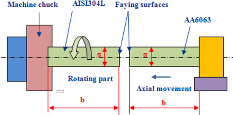
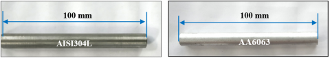
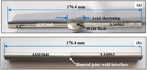
The friction welding machine (Model: KAKA, German make-capable of 15 ton.) was used for the experiments. The features of the machine are 3000 rpm maximum, 5-ton heating force maximum, and 15-ton upsetting force maximum. The machine can be used for welding of rods/pipes having a maximum welding area of 1000 mm-2 and can also be used for many similar and dissimilar material combinations. In this study, the joints of dissimilar alloys were fabricated through a rotary friction welding process with combined welding parameters as per L9 orthogonal array. To reduce the problem of generating intermetallic compounds while the FW process, the welding parameters must be considered for the sound welding joints. The formation of FeAl3 brittle phase can be avoided by increasing the welding speed [28]. AA6063 is a soft material but AISI304L is moderately hard, so reasonable friction pressure may be enough to get good bonding between them [29, 30]. Friction pressure (FP), upset pressure (UP), forging time, friction time (FT), Rotation speed, and the axial penetration rate are the important parameters in friction welding method [31, 32]. Normally UP is maintained greater than FP. The varying and the constant parameters and their values used for the experiments at room temperature are given in Table 4. The various welding conditions and the experimental trials to be carried out according to L9 orthogonal array are given in Table 5. Schematic description of the experimental work tried in this study is given in Figure 1. Cylindrical rods of length 100 mm and diameter of 12 mm were machined for the weld specimens (Figure 2). Faying surface cleanliness in terms of contaminants is important since it reduces the quality of joints [33]. Here, Acetone was used to remove such contaminants (grease, dust, oil, rust, etc) before the FW to minimize organic contaminants in the welding region. After the welding, the formation of honeycomb shape on the friction welded specimen is clearly shown in Figure 3a (image of Exp. 5) and the axial length reduction was also noted in the aluminium side than that of the steel side. The bimetal joint with weld flash of aluminium expelled during FW is seen in Figure 3a and the machined joint for further study is also shown in Figure 3b. Weld flash mainly happens due to the low melting point of aluminium than that of stainless steel. The plasticized materials called flash came out due to the rotational speed of the chuck, but the quantity and intensity of flash were varied with different welding parameters. If friction pressure (FP) and feed rate are increased, the quantity of flash also increased and material loss also increased.
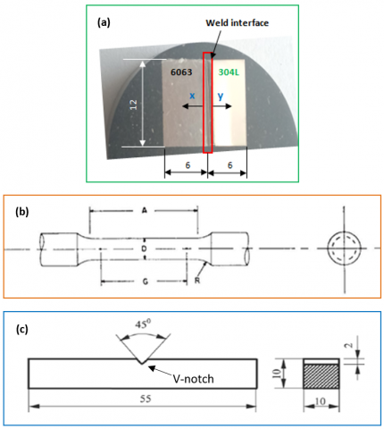
The decision was taken during the experiment that the low friction & upset pressures (for Exp. 1, 2, 3) were inadequate to cause ring shape flash formation and the low flash was extruded from the weld interface. For analyzing the weld joint integrity, initially, drop test, which means to drop the welded specimen from the one-meter height, was done on friction welded specimen to identify the failure. Once the specimen succeeds in the drop test, tensile strength, hardness and impact values were measured for all welded samples with the sophisticated equipment. Sample preparation for the entire test is crucial to evaluate the properties of welded samples. Here, the samples were prepared as per American Society for Testing and Materials (ASTM) standards. Microhardness distribution was evaluated (Figure 4c) using Vickers hardness tester along the various zones like base metal (BM), weld interface area and heat-affected zone (HAZ) of both AA6063 and AISI304L sides. Dwelling time of 15 seconds was maintained for the hardness measurement. Tensile properties of the weld specimen were measured using a testing machine (MTS 10 kN INSIGHT) as per ASTM E8 standard (Figure 4b). Impact energy is a measure (in terms of Joules) of the amount of energy that a material can absorb before fracturing by a suddenly applied load under a high rate of deformation. Impact energy of welded samples were measured by Charpy impact test at room temperature as the temperature influences the impact toughness [34]. Samples and V-notch have to be carefully prepared according to the standard ASTM E23 (Figure 4c) in such a way that no grooves appear at the base of the notch. The sample dimensions for impact testing were 55 mm length, 10 mm width & height, 45°angle of the notch, 2 mm notch height and 8 mm height of ‘below notch’. Metallography has been the study of the microscopic structure of metals and alloys and weld joints. By analyzing materials’ microstructure, its performance and reliability can be better understood. Micro-characterization includes the identifications of grain size, porosity and voids, dendritic growth, cracks and other defects, stress corrosion cracking, weld and heat-affected zones, identification of deleterious intermetallic phases in the welded joints. In this work, optical microscopy (OM) and field emission scanning electron microscopy (FESEM) were used for microstructures analysis of welded joint and for the fracture analysis on the specimen after tensile and impact testing. The samples were cut from the welded portion and polished for the morphological study. Since the joints prepared by exp. no.5 (FP-15 MPa, UP-21, FT- 7 sec) show good results considering overall properties and the welding conditions are the minima required for the acceptable joints, the specimens prepared from exp. 5 is used for the microstructure and fracture characterisation. The corrosion study on the welds by salt spray testing at 35 °C was done according to ASTM B117-16 standard and no corrosion was found in the weld zone.
Table 4. Experimental parameters and their levels for this study
|
Parameters |
Level 1 |
level 2 |
level 3 |
|
Friction pressure (MPa) |
12 |
15 |
18 |
|
Upset pressure (MPa) |
18 |
21 |
24 |
|
Friction Time (sec.) |
3 |
5 |
7 |
|
Whereas, constant parameters and their values: Rotational speed=1300 rpm, upset time= 3 seconds, and axial penetration rate during FW=3 m/min. |
|||
|
Experimental Trials |
Welding conditions for various welding trials |
||
|
Friction pressure FP (MPa) |
Upset pressure UP (MPa) |
Friction time FT (sec.) |
|
|
Exp.1 |
12 |
18 |
3 |
|
Exp.2 |
12 |
21 |
5 |
|
Exp.3 |
12 |
24 |
7 |
|
Exp.4 |
15 |
18 |
5 |
|
Exp.5 |
15 |
21 |
7 |
|
Exp.6 |
15 |
24 |
3 |
|
Exp.7 |
18 |
18 |
7 |
|
Exp.8 |
18 |
21 |
3 |
|
Exp.9 |
18 |
24 |
5 |
Figure 2. Weld specimens (ϕ12 mm dia.) prepared for dissimilar frictional joining
Figure 3. Bimetal joint prepared by welding conditions at experiment no. 5, where (a) bimetal weld (ϕ12mm dia.) before machining, (b) bimetal weld (ϕ12mm dia.) after flash removal machining
Figure 4. Test specimen dimension (in ‘mm’) for (a) microhardness measurement at x, y direction towards base metal from WI, (b) tensile test where, D-9 dia., G-45, A-54, R-8, (c) V-notch impact test
3.1 Microstructure characterization
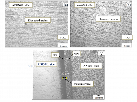
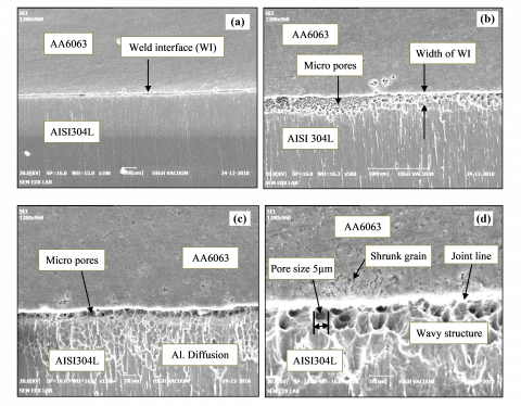
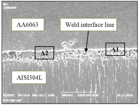
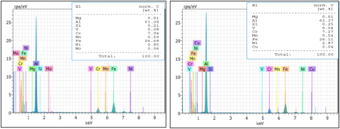
Microstructural changes after the FW by reason of deformation and heat generation were noted and given in Figure 5 (a-c). From the Figure 5a, deformed stainless steel with grains modified is observed and Figure 4b shows the deformation on the aluminium side that shows the effect of FP, UP and FT and influence of penetration and friction between the faying surfaces during FW. Welding interface in the dissimilar joint is clearly visible in Figure 4c and the width of the weld interface was noted as 20 microns. The microimages are evident that the weld has good bonding between AISI304L (SS) and AA6063 (Al.) dissimilar metals. The microstructural pattern on stainless steel side of fine grains and the deformed region is manifest of increase in hardness near the weld interface or HAZ than the base metal (BM) away from the weld interface. The SEM images of the dissimilar joint are shown in Figure 6. The images were taken at various regions nearby weld interface under high vacuum. The different images were identified and given in this paper. From the SEM images (Figures 6.a to 6.d), the weld interface or welded joint of dissimilar metals is evident and clearly visible and the strong nature is also recorded and it was observed that the strong weld was formed due to friction during welding between the two dissimilar metals. The Figures clearly show the weld boundary between two metals. Figures 6 a & b proved the formation of an interface between SS and Al. in a perfect manner with dimple nature during friction welding and intermetallic nearby is also noted. The width of the weld interface (WI) is a maximum of 15-20 microns and calculated from Figures 6 c & d. The elongated grains are also visible nearby SS joint it may improve the strength of the weld nearby SS zone and the deformation is there in Al. zone it may worsen the strength nearby the aluminium zone of the weld. Figure 6 d (10 µm size) also shows the formation of micropores or voids in the weld interface along with the heat-affected zone and also grains. Though the size of the pores of 5µm is identified in the weld joint line, the bimetal joint is good and the diffusion during the FW with increased friction pressure forms a wavy structure in a 6063 zone in the image of the welded joint. The damaged grains are also noted due to huge force during the FW, it also proves the development of ductility partially. The pore sizes are noted as 5 microns maximum. Thus, the SEM images are the proof for partially ductile natures, deformed zone, good WI and enough pressure for FW joint. Energy-dispersive X-ray Spectroscopy (EDX) analysis was used to measure the composition, nature of the matrix and chemical element distribution and analyze fracture surface at the welded zone. EDX was performed for investigating the phases during the welding at weld boundary of two dissimilar metals. The observation was with 15 kV. The results of the welded joint obviously show the major elements present and quality of the welded joint. Figure 7 shows dissimilar weld boundary regions 1 and 2 (A1, A2 of figure 8) from where EDX analysis was done to identify the components available in the weld joint. Figure 8 was the EDX charts for various regions nearby weld joint for the intensity of components present at regions 1 & 2. The elements formed at the interface/joint during welding were observed by EDX spectra. In the spectra, the elements presented are Mg, Al, Si, V, Cr, Mn, Fe, Ni, and Cu but in some areas the element ‘Mo’ formation was also observed in EDX spectrum at region A2. ‘Mo’ improves the pitting corrosion properties of the joint. The ‘Mo’ was formed from the carbide phase of M23C6 at the austenite grain surfaces where ‘M’ is the mixture of metal atoms of iron, molybdenum, chromium and manganese depending on the steel composition and temperature in weld interface. 26 % ‘Fe’ content value is high next to the aluminium percentage of 62.37 followed by chromium 7.27%, from this ‘Fe’ content value’s change; it is proved the diffusion of ‘Fe’ into AA6063 zone. EDX shows the Fe-Al intermetallics like Fe2Al5 formation. Here the percentage of nickel (Ni) was noted as 2.87, a small amount of the Ni is enough to form nickel-based intermetallic compounds. There is a possibility to raise the corrosion resistance of the welded specimen since it contains a huge amount of chromium. EDX analysis defined on SEM microstructure in welding boundary of the friction welded SS-Al dissimilar joints. The EDX results taken from areas 1, 2 respectively in welded joint and the formation of intermetallics was also confirmed with the spectra obtained. The weight of the alloying elements present is shown in the spectrum of the welded joints. It is observed that in some areas nearby weld interface small amount of molybdenum (Mo) is recorded that means the corrosion resistance of weld zone would be much better due to FW than that of base AISI304L. The percentage of aluminium is recorded around 62% in both spectra at A1 & A2 compared with the value of 98% of aluminium (Al) in the base metal. Similarly, the iron (Fe) content is also recorded as 26% nearby interface region, which is a prime one to have ‘Fe’ related intermetallic. In the welded joint, the amount of Nickel (Ni) and Chromium (Cr) was observed as 7% and 3% respectively. Thus, the reduction of ‘Al’ and ‘Fe’ content confirmed the joint of dissimilar metals, the formation of the intermetallics and the reaction between AISI304L and AA6063 during the friction welding.
Figure 5. Optical micrographs of welded specimen (of Exp. no. 5) and joint interface. a & b - HAZ of AISI304L and AA6063 part in dissimilar joint respectively, c- Weld interface of bimetal joint.
Figure 6. SEM images of weld joint at the conditions of Exp. no. 5 (a to d)
Figure 7. EDX scan areas in weld interface of specimen from exp. no. 5
Figure 8. EDX spectrum at region A2, A1
3.2 Mechanical characterization
3.2.1 Microhardness
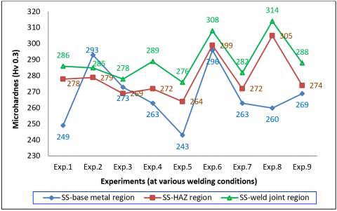
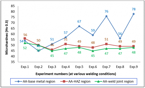
The hardness distribution across the weld is from weld interface towards base metals asymmetrical and the plots were drawn with the hardness values observed across the weld region from its centre. From results, it is observed that the hardness values of HAZ are higher than that for the base metal in AISI304L side. The thing is pointing out that the HAZ was narrow and was not affected by forces while friction welding at different experiments [35]. But in case of AA6063 side, the hardness values of HAZ are comparatively lower than the base metal since it was severely affected by the obligation generated by the insertion of AISI304L side (rotating part) into AA6063 side (stationary part). That will frame soft nature near the weld interface zone and this softness reduced the hardness. Aluminium recrystallized on account of friction heat and deformation, thus aluminium softened and there was a change in both materials in hardness after the FW. The microhardness value is of maximum at the nearby AISI304L weld interface. During this study, it was observed that the hardness on AISI304L side of the welded specimen decreases as it is advanced towards the end side of the specimen. But conversely, that was to AA6063 side. Figure 9 & 10 shows the microhardness distribution along the weld zones of both AA and SS from weld interface according to the different welding conditions (experiments 1-9, Table 5) done during FW. From the average values, the graphs are drawn. Figure 8 shows the microhardness of stainless steel side and figure 9 is for the aluminium side of bimetal weldment. The maximum hardness was recorded as 314 Hv0.3 at weld interface nearby AISI304L for the 8th experiment, in which the FT was 3 sec. This value is compared to the first experiment since it had experimented with less mechanical/axial force due to low FP, UP but same FT. The reason for high hardness nearby SS weld joint is the grain refinement during FW at opt welding parameters. The small grains increase hardness. In figure 8, the hardness values are varied as per the changes took place in welding parameters during FW. Exp. 6 having 308 Hv0.3 was also with 3 sec. FT. FW with 3 sec. shows good microhardness in SS side. For SS base metal, the hardness value kept a maximum of 296 Hv for the 6th experiment. Whereas at weld joint region of the AA side, the hardness was decreased due to the shrunk grains by FW force as shown in figure 9. Experiment 1 shows maximum hardness nearby AA weld joint in Figure 9. The microhardness nearby AA weld region is lower than AA base metal region. Considering figure 9, the hardness value at HAZ is moderate between base metal and weld zone. From the figure 9, the hardness values at HAZ of AA region & weld interface region are higher for exp. 1 than others, but the hardness at AA base metal region is higher for the 9th experiment than others. Though the hardness value for the 7th experiment is good, the 9th experiment is much better than 7th as it has maximum hardness at AA weld region (78 Hv 0.3) and AA base metal region (48 Hv0.3). The maximum hardness value 52 Hv0.3 and 56 Hv0.3 were recorded at interface and HAZ of AA region respectively for 1st experiment with low parameters. In HAZ of aluminium (Al.) zone, the hardness distribution was observed as low and not acceptable changes in value among all experiments. The hardness distribution range is 48-58 MPa in HAZ of aluminium due to the heavy force acted onto HAZ of AA6063 during FW. But in aluminium base metals, the values are initially almost maintained constant and start to increase gradually. Put differently, the value of HAZ for the aluminium zone was inferior to that of AA base metal. The hardness of AISI304L HAZ is about 5 times greater than that of AA6063. The hardness value is not clearly identified and may be negligible in the dissimilar weld interface [36]. The hardness values changed when the friction pressures were changed as it is one of the most influencing factors on the hardness of weld joint. From the results, it is supposed that friction time (FT) 3 seconds in welding conditions showed reasonable results. From the consequence, FT is vital for hardness distribution among various zones. FT 7 sec. is having low hardness due to deformation and more time for rising soft nature on weld metals during the FW.
Figure 9. Microhardness for all experiments at various regions in weld zone along SS304L side of dissimilar weld joint
Figure 10. Microhardness for all experiments at various regions in weld zone along AA6063 side on dissimilar weld joint
3.2.2 Impact energy and fracture study
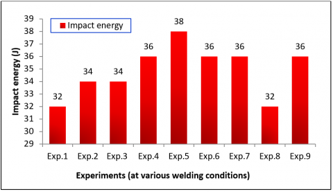
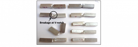
During the impact test, the values were observed for all experiments (Table 5) and are reported in Figure 11. The breakage was held at the V-notch (portion at weld joint) of all specimens as shown in figure 12. From the test, it was observed that the formation of ductility was good for the experiments done with friction pressure 15 MPa & 18 MPa but the weld joints prepared by friction pressure 12 MPa shows brittleness. The maximum energy observed was around 38 joules for the 5th experiment with 7 seconds friction time and 15 MPa friction pressure. The common factor between the 1st and 8th experiment is the friction time of 3 sec. and both have the lowest impact value of 32 Joule. Measurement of impact energy of the weldment or new materials is mandatory for almost all engineering applications to identify the tendency of fracture during sudden load. From the results obtained, friction pressure and friction time play an important role in improving the toughness value. At the time of FW between SS and AA alloys, the category of Fe-Al intermetallics formation was possible and could it stable more at low welding conditions by reducing the toughness value.
Figure 11. Impact energy values of friction-welded dissimilar joints
The fracture analysis was done for further failure investigation on the impact tested specimen made based on exp. 5 welding conditions since it showed maximum value. Scanning electron microscope (SEM) images are suitable for the fractography analysis on the fractured joint [37]. Figure 13a shows the fractography images of SEM images of fractured specimens after the impact test. Figure 13a shows the formation of dimple fracture and less degree brittleness on the weld and a congested kind of portion was observed. Figure 13b is the proof of the ring pattern formation on the AA6063 due to the rotary motion of the FW machine, it shows enough FP was achieved during FW. Similarly, Figures 13c & 13d are of AISI304L portions of impact tested specimen. These are also showing the attachment of debris in a few micron sizes of aluminium 6063 onto AISI304L during the testing. The plain surface was observed in SS part of dissimilar FW welded joint after the impact test and shown in figure 13c but it showed little brittleness. The ring formation on the SS portion is visible in Figure 13d, which shows the frictional joining and much rotation of 304L part and strong response between the AA and SS parts during the FW. While comparing the ring patterns on the AA and SS (Figure b, d respectively) parts after impact testing, it was found that a number of rings more in AA part dimple fracture on the ring was also formed and the AA debris in traces was sticking on SS side.
Figure 12. Charpy V-notch tested specimens
Figure 13. SEM fractography images of impact test specimen at welding conditions (Exp. 5)
3.2.3 Tensile strength and fracture study
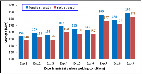
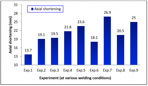
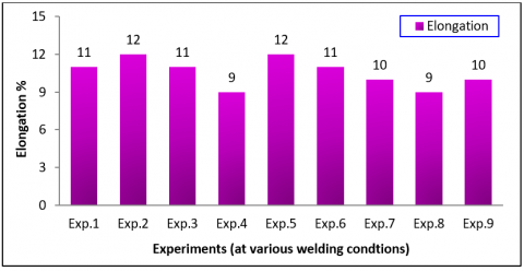
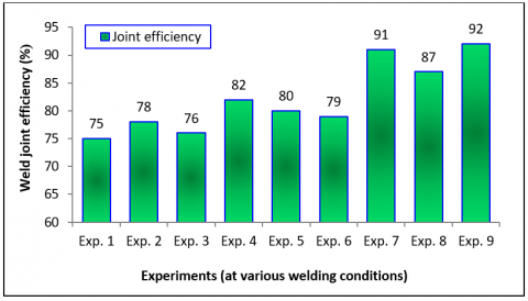
The welded specimen before testing is shown in figure 14a and the tested specimen of Exp.no.9 & Exp.no.5 after tensile testing are given in Figures 14b & c respectively. The test was done on the specimen of all 9 experiments at different welding conditions (from exp. no. 1 to ex no. 9), and the values observed are plotted in Figures 15- 17. During testing there was no plastic deformation on tensile specimen produced by 12 MPa friction pressure (figure 14c) and the plastic deformation with cup and cone structure was formed on the specimen welded with 18 MPa (figure 14b). Most of the welds were broken outside of the weld joint. The peak load was obtained a maximum of 12 kN. It is understood that the friction time is one of the main factors which influences the strength of the friction-welded joint next to friction pressure. The maximum strength is recorded as 189 MPa for the 9th experiment which is almost equal to the strength of AA base metal. The friction pressure 18 MPa produced maximum strength than that of 15 MPa and 12 MPa. While changing friction time and upset pressure, but maintaining the friction pressure as constant, the value was reduced a little bit as 186 MPa. It is worth to note down that the tensile values are having maximum values for friction time 5 seconds followed by 7 seconds and 3 seconds. Though all the trial parameters were well in welding, it was identified from the tensile results that the minimum required welding conditions for sufficient strength were 15 MPa FP, 21 MPa UP and 7 FT as in exp.no.5 (figure 14 c) as the weld joint produced around 80% strength (165 MPa) of AA base metal (205 MPa, Table 3). It is essential to compare the tensile and yield strength of all-welded specimen and how the improvement was there in the welded specimen according to parameters variation was observed. Figure 15 shows the comparison of tensile and yield strength of the welded joints fabricated by various welding conditions. The maximum value of both tensile and yield strengths were recorded for the experiment no.9 which was with 18 MPa friction pressure. Friction pressure less than 15 MPa shows the insufficient strength but the expected strength for industrial applications were found in the experiment nos. 5 to 9. So the friction pressure might be good for an effective weld if it is maintained above 15 MPa during FW furthermore the upset pressure (UP) should be maintained above or equal to the friction pressure trailed in all experiments. Upset pressure value higher than friction pressure depends on the diameter of the rods and the materials to be joined. The UP is better if it is fixed around 30% over FP. The formation of brittle intermetallics at the weld interface should be avoided during welding to stop the reduction of weld strength. Axial shortening is an important one during FW which determines the material loss after the friction welding comparing the total length of the weld specimens before welding with the length of weldment after FW. The axial shortenings for the experiments 1-9 are given in figure 16. The values were comparatively high when increasing friction pressure over a long friction time. For example, the axial shortening for 12 MPa FP, 18 MPa UP & 3 sec FT was recorded as 13.7 mm, but the same was identified as a maximum of 26.9 mm for the welding conditions 18 MPa FP, 18 MPa UP & 7 FT sec. This was due to the vigorous force developed by axial movement of AA in the friction welding machine with maximum pressure. It is also observed during FW that the axial shortening was low while decreasing friction time. The weld joint with low axial shortening and maximum strength is appreciable in friction welding between ferrous and non-ferrous materials. The experiment no. 5 shows the good results on axial shortening with the value of around 23 mm while considering tensile strength and at 15 MPa friction pressure, which is the minimum required pressure for joining these ϕ12 mm specimens through FW. Welding with 3 seconds of friction time got low axial shortening. From results, the parameters FP, FT and UP have a direct effect on the strength of welded joints. When friction pressure increased the peak load of the weld joint was also increased. An increase in friction pressure (FP) will increase the tensile strength by making the strong bonding between the elements of both metals. Figure 17 shows the elongation of weld joints, low welding pressure shows maximum elongation. Parameter friction time (FT) has an impact on tensile strength since 7 sec FT produced maximum elongation. An elongation of 12% of the 5th experiment and has a good impact on the mechanical properties of weld joints while selecting minimum welding parameters required. Figure 18 furnishes the welded joint efficiency (η) comparison of all experiments. Joint efficiency determines the weld quality and is the ratio of the tensile strength of a welded joint to that of base metal. The maximum efficiency is 92 % for the 9th experiment. But the 5th experiment has 80 % weld efficiency with the minimum required welding conditions for the joining.
Figure 14. Tensile specimen as per standard before testing (a), 9th experiment specimen after tensile breakage (b), and 5th experiment specimen after tensile breakage
Figure 15. Tensile and yield strength of friction welded joints
Figure 16. Axial shortening measured during friction welding
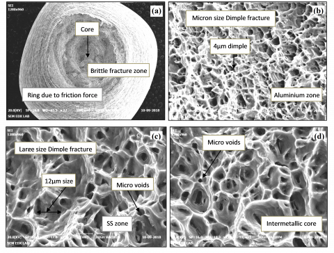
The fracture analysis was done for further failure investigation on the tensile tested specimen of Exp. no. 9 since it shows the maximum tensile value. Actually, metallurgical failure analysis is the process by which the mechanism that has caused a metal component to fail. The neck formation during the fracture of the welded joint and the failure took place at the outside of the weld are clearly visible in Figure 14b & c. The figures also show information about the plastic deformation and elongation happened during the tensile load. The fracture is under diverse way of brittle and ductile fracture and also it is obvious that some amount of aluminium metal is sticking on the stainless steel side. But such kind of ductile fracture was not seen on the specimens prepared by friction pressure 12 MPa. The specimen fabricated with the welding conditions 15 MPa friction pressure, 21 MPa upset pressure, 7 seconds friction time showed appreciable ductile fracture with dimple structure. Figure 19 shows the FESEM images of fractography characteristic of tensile tested samples of welds, which were taken at different regions in the fracture of the samples (Exp.no. 9). In the case of joints, weak bonding is also observed at low pressure. With a view to understanding the nature of the fracture, the fractured surfaces at both SS and AA sides are analyzed and the fracture morphology of tensile tested samples of Exp. no. 9 (which has maximum tensile strength) is presented in Figure 19 (a to d). Fracture surfaces vary in the physical appearance of a rough surface to flat wavy surface as the friction time increases from 1s to 6s [38]. The brittle fracture zone of fractured weld metals (Figure 19.a), the fractured specimen on the aluminium side (Figure 19.b), the fractured specimen on the stainless steel side (Figure 19.c), and Intermetallic core zone (Figure 19.d) were analyzed under FESEM instrument. It shows the ring pattern and the ductile bonding [39] after hard-working of brittle fracture. At higher magnification, the fracture morphology shows the presence of dimples which are the indication of tensile fracture. Figure 19.b revealed the dimple rupture with ductile nature nearby joint on AA6063 side; it was the indication of improving the strength of the weld joint at low pressure. But the partial brittleness due to insufficient plasticity on the stainless steel side is shown in Figure 19.c. The voids developed during a fracture on SS (around 7-12 µm) are bigger than the AA side in size (around 3-7 µm), which may be clearly compared in Figures 19.b (AA side) & 19.c (SS side). From the Figure 19.d, it is taken into account that the fracture formation on intermetallic core zone is confirmed with brittle but good bonding between two metals and the void sizes are noted around 12 microns (µm). Though the time duration and pressure for the joining are enough, it is still partially brittle with dimple structure due to the brittle intermetallics. This is the reason why strength is appreciably good nearby weld zone with having ductile nature in the intermetallic zone.
Figure 17. Elongation of dissimilar joints during tensile testing
Figure 18. Weld joint efficiency for all experiments
Figure 19. Fractography analysis of the tensile tested specimen (welding conditions as per Exp. no. 9), Where a-100 µm, b, c, d- 10 µm
In this study, the dissimilar alloys AISI304L and AA6063 were successfully joined by rotary friction welding (RFW) at welding conditions as per L9 orthogonal array. The essential level of processing parameters required for the joining was identified for an excellent joint through this study. The minimum required welding parameters for joining of both dissimilar metals are 15 MPa FP, 21 MPa UP and 7 sec. FT with 80% joint efficiency, whereas a maximum of 92% joint efficiency is obtained by consuming low welding pressures for 18 MPa FP, 24 MPa UP, 5 Sec FT conditions. The Microstructure study showed the narrow-size (20 µm) weld interface and HAZ. The micropores of size about 5 µm were due to inadequate bonding. Intermetallics compounds formations were confirmed and the formation of molybdenum (Mo) in a weld interface was also observed through EDX study, which may improve the corrosion resistance of weld joint fabricated. The formation of ‘Mo’ may be due to the carbide phase of M23C6 at the austenite grain surfaces where ‘M’ is the mixture of iron, molybdenum, chromium. Fe (26 %) is recorded in the weld interface next to 62% Aluminium. The partial diffusion of iron content from steel and aluminium content from the base metal happened in the interface region. Fractography analysis showed the dimple rupture and the formation of ductility on the fractured zone. The ring formation indicates enough rotation happened during RFW. The pores formation was noted as less for AA than the SS part. From the tensile results, ample heat to obtain strong joint could not be generated for friction time 3 seconds. It was further noted that if the axial penetration rate and upset time rises, the strength of the welded joint might increase. If the UP is higher than FP, that would produce good results. The hardness of the AISI304L side is higher nearby weld interface but vice versa in AA6063 side of the dissimilar joint. In this study, FP & FT are the major factors for hardness improvement. Impact toughness showed the minor form of ductile fracture on the welded joint.
[1] Schmicker, D., Persson, P.O., Strackeljan, J. (2014). Implicit geometry meshing for the simulation of rotary friction welding. Journal of Computational Physics, 270: 478-489. https://doi.org/10.1016/j.jcp.2014.04.014
[2] Uday, M.B., Ahmad Fauzi, M.N., Zuhailawati, H., Ismail, A.B. (2010). Advances in friction welding process: a review. Science and technology of Welding and Joining, 15(7): 534-558. https://doi.org/10.1179/136217110X12785889550064
[3] Ambroziak, A., Korzeniowski, M., Kustroń, P., Winnicki, M., Sokołowski, P., Harapińska, E. (2014). Friction welding of aluminium and aluminium alloys with steel. Advances in Materials Science and Engineering, 2014. https://doi.org/10.1155/2014/981653
[4] Polami, S.M., Reinhardt, R., Rethmeier, M., Schmid, A. (2014). Joint-site structure friction welding method as a tool for drive pinion light weighting in heavy-duty trucks. Journal of Materials Processing Technology, 214(9): 1921-1927. https://doi.org/10.1016/j.jmatprotec.2014.03.027.
[5] Tenaglia, R. (2012). Dissimilar Materials Joining.
[6] Sharma, C., Upadhyay, V., Narwariya, B.S. (2018). Tensile properties of dissimilar friction stir weld joints of Al-2024 and Al-7039 alloys. Materials Research Express, 6(2): 026524. https://doi.org/10.1088/2053-1591/aaeca3
[7] James, J.A., Sudhish, R. (2016). Study on Effect of Interlayer in Friction welding for Dissimilar Steels: SS 304 and AISI 1040. Procedia Technology, 25: 1191-1198. https://doi.org/10.1016/j.protcy.2016.08.238
[8] Mercan, S., Aydin, S., Özdemir, N. (2015). Effect of welding parameters on the fatigue properties of dissimilar AISI 2205–AISI 1020 joined by friction welding. International Journal of Fatigue, 81: 78-90. https://doi.org/10.1016/j.ijfatigue.2015.07.023
[9] Singh, R., Kumar, R., Feo, L., Fraternali, F. (2016). Friction welding of dissimilar plastic/polymer materials with metal powder reinforcement for engineering applications. Composites Part B: Engineering, 101: 77-86. https://doi.org/10.1016/j.compositesb.2016.06.082
[10] Sathiya, P., Aravindan, S., Haq, A.N. (2007). Effect of friction welding parameters on mechanical and metallurgical properties of ferritic stainless steel. The International Journal of Advanced Manufacturing Technology, 31(11-12): 1076-1082. https://doi.org/10.1007/s00170-005-0285-5.
[11] Rengarajan, S., Rao, V.S. (2015). Characteristics of AA7075-T6 AND AA6061-T6 friction welded joints. Transactions of the Canadian Society for Mechanical Engineering, 39(4): 845-854. https://doi.org/10.1139/tcsme-2015-0067
[12] Singh, S.K., Chattopadhyay, K., Phanikumar, G., Dutta, P. (2014). Experimental and numerical studies on friction welding of thixocast A356 aluminum alloy. Acta Materialia, 73: 177-185. https://doi.org/10.1016/j.actamat.2014.04.019
[13] Selvamani, S.T., Palanikumar, K. (2014). Optimizing the friction welding parameters to attain maximum tensile strength in AISI 1035 grade carbon steel rods. Measurement, 53: 10-21. https://doi.org/10.1016/j.measurement.2014.03.008
[14] Song, X., Xie, M., Hofmann, F., Jun, T.S., Connolley, T., Reinhard, C., Korsunsky, A.M. (2013). Residual stresses in linear friction welding of aluminium alloys. Materials & Design, 50: 360-369. https://doi.org/10.1016/j.matdes.2013.03.051
[15] Van Niekerk, C.J., Du Toit, M. (2011). Sensitization behaviour of 11-12% Cr AISI 409 stainless steel during low heat input welding. Journal of the Southern African Institute of Mining and Metallurgy, 111(4): 243-256.
[16] Yang, X., Li, W., Xu, Y., Wen, Q., Feng, W., Wang, Y. (2019). Effect of welding speed on microstructures and mechanical properties of Al/Cu bimetal composite tubes by a novel friction-based welding process. Welding in the World, 63(1): 127-136. https://doi.org/10.1007/s40194-018-0652-0
[17] Rotundo, F., Marconi, A., Morri, A., Ceschini, A. (2013). Dissimilar linear friction welding between a SiC particle reinforced aluminum composite and a monolithic aluminum alloy: Microstructural, tensile and fatigue properties. Materials Science and Engineering: A, 559: 852-860. https://doi.org/10.1016/j.msea.2012.09.033
[18] Tung, D.J., Mahaffey, D.W., Senkov, O.N., Semiatin, S. L., Zhang, W. (2019). Transient behaviour of torque and process efficiency during inertia friction welding. Science and Technology of Welding and Joining, 24(2): 136-147. https://doi.org/10.1080/13621718.2018.1491377
[19] Kuznetsov, M.A., Zernin, E.A. (2012). Nanotechnologies and nanomaterials in welding production. Welding international, 1-3. https://doi.org/10.1080/09507116.2012.715902.
[20] Fukumoto, S., Inoue, T., Mizuno, S., Okita, K., Tomita, T., Yamamoto, A. (2010). Friction welding of TiNi alloy to stainless steel using Ni interlayer. Science and Technology of Welding and Joining, 15(2): 124-130. https://doi.org/10.1179/136217109X12577814486692
[21] Meshram, S.D., Reddy, G.M. (2015). Friction welding of AA6061 to AISI 4340 using silver interlayer. Defence Technology, 11(3): 292-298. https://doi.org/10.1016/j.dt.2015.05.007
[22] Buffa, G., Campanella, D., Pellegrino, S., Fratini, L. (2016). Weld quality prediction in linear friction welding of AA6082-T6 through an integrated numerical tool. Journal of Materials Processing Technology, 231: 389-396. http://doi.org/10.1016/j.jmatprotec.2016.01.012
[23] Besler, F.A., Schindele, P., Grant, R.J., Stegmüller, M.J. (2016). Friction crush welding of aluminium, copper and steel sheetmetals with flanged edges. Journal of Materials Processing Technology, 234: 72-83. https://doi.org/10.1016/j.jmatprotec.2016.03.012
[24] Cheepu, M., Ashfaq, M., Muthupandi, V. (2017). A new approach for using interlayer and analysis of the friction welding of titanium to stainless steel. Transactions of the Indian Institute of Metals, 70(10): 2591-2600. https://doi.org/10.1007/s12666-017-1114-x
[25] Uday, M.B., Fauzi, M.A., Zuhailawati, H., Ismail, A.B. (2011). Evaluation of interfacial bonding in dissimilar materials of YSZ–alumina composites to 6061 aluminium alloy using friction welding. Materials Science and Engineering: A, 528(3): 1348-1359. https://doi.org/10.1016/j.msea.2010.10.060
[26] Guo, W., You, G., Yuan, G., Zhang, X. (2017). Microstructure and mechanical properties of dissimilar inertia friction welding of 7A04 aluminum alloy to AZ31 magnesium alloy. Journal of alloys and compounds, 695: 3267-3277. https://doi.org/10.1016/j.jallcom.2016.11.218
[27] Coetzee, P.G.H. (1995). The welding of experimental low-nickel Cr-Mn-N stainless steels containing copper. Journal of the Southern African Institute of Mining and Metallurgy, 96(3): 99-108.
[28] Leitao, C., Arruti, E., Aldanondo, E., Rodrigues, D. M. (2016). Aluminium-steel lap joining by multipass friction stir welding. Materials & Design, 106: 153-160. https://doi.org/10.1016/j.matdes.2016.05.101
[29] Mani, D. (2017). Welding Mechanisms during Friction Welding of Aluminium with Steel. Journal of Chemical and Pharmaceutical Sciences, 7.
[30] Shanjeevi, C., Arputhabalan, J., Pavithran, E., Raju, B. (2019). Prediction of Optimized Friction Welding Parameter for Joining of Dissimilar Material using Friction Welding. Materials Today: Proceedings, 16: 838-842. https://doi.org/10.1016/j.matpr.2019.05.166
[31] Kannan, P., Balamurugan, K., Thirunavukkarasu, K. (2015). Influence of silver interlayer in dissimilar 6061-T6 aluminum MMC and AISI 304 stainless steel friction welds. The International Journal of Advanced Manufacturing Technology, 81(9-12): 1743-1756. https://doi.org/10.1007/s00170-015-7288-7
[32] Ajith, P.M., Husain, T.A., Sathiya, P., Aravindan, S. (2015). Multi-objective optimization of continuous drive friction welding process parameters using response surface methodology with intelligent optimization algorithm. Journal of Iron and Steel Research, International, 22(10): 954-960. https://doi.org/10.1016/S1006-706X(15)30096-0
[33] Sahin, M., Misirli, C. (2012). Mechanical and metalurgical properties of friction welded aluminium joints. Aluminium alloys-new trends in fabrication and applications, 277-300. https://doi.org/10.5772/51130
[34] Muralimohan, C.H., Haribabu, S., Reddy, Y.H., Muthupandi, V., Sivaprasad, K. (2014). Evaluation of microstructures and mechanical properties of dissimilar materials by friction welding. Procedia Materials Science, 5: 1107-1113. https://doi.org/10.1016/j.mspro.2014.07.404
[35] Kimura, M., Kusaka, M., Kaizu, K., Nakata, K., Nagatsuka, K. (2016). Friction welding technique and joint properties of thin-walled pipe friction-welded joint between type 6063 aluminum alloy and AISI 304 austenitic stainless steel. The International Journal of Advanced Manufacturing Technology, 82(1-4): 489-499. https://doi.org/10.1007/s00170-015-7384-8
[36] Shanjeevi, C., Kumar, S.S., Sathiya, P. (2013). Evaluation of mechanical and metallurgical properties of dissimilar materials by friction welding. Procedia Engineering, 64: 1514-1523. https://doi.org/10.1016/j.proeng.2013.09.233
[37] Frei, J., Alexandrov, B.T., Rethmeier, M. (2019). Low heat input gas metal arc welding for dissimilar metal weld overlays part III: hydrogen-assisted cracking susceptibility. Welding in the World, 63(3): 591-598. https://doi.org/10.1007/s40194-018-0674-7.
[38] Muralimohan, C.H., Muthupandi, V., Sivaprasad, K. (2014). Properties of friction welding titanium-stainless steel joints with a nickel interlayer. Procedia Materials Science, 5: 1120-1129. 10.1016/j.mspro.2014.07.406.
[39] Sahin, M. (2010). Joining of aluminium and copper materials with friction welding. the International Journal of advanced Manufacturing technology, 49(5-8): 527-534. http://doi.org/10.1007/s00170-009-2443-7