Haiat Bourenane* | Abderrahmane Berkani![]() | Karim Negadi
| Karim Negadi![]() | Fabrizio Marignetti
| Fabrizio Marignetti![]() | Khaled Hebri
| Khaled Hebri
© 2023 IIETA. This article is published by IIETA and is licensed under the CC BY 4.0 license (http://creativecommons.org/licenses/by/4.0/).
OPEN ACCESS
Integrating solar energy in electric vehicles (EV) is expected to play a dominant role in the decarbonization of the transportation sector as well as reducing the charging costs. These integrated photovoltaic automobiles are particularly adapted for urban driving that is to say the driving range is limited. On that account, the use of a feasible energy storage system is necessary to boost the driving mileage. This paper uses a hybrid energy system, containing a battery as the main storage device and a supercapacitor (SC) as a backup. This combination was suggested in order to negate the former’s deficiencies. The use of a hybrid energy source leads to the necessity of introducing a robust power management strategy to guarantee the optimal power flow in electric vehicle components. An artificial neural network is then trained with model calculation for the power management approach for the traction chain. The results of the simulation indicate that the proposed system is efficient in improving the energy management of the vehicle. Moreover, the system's simplicity could potentially make it easier to implement in real-time using a DSP or a Dspace platform.
artificial neural networks, power management, battery, hybrid energy storage system, electric vehicle
The exponential growth of energy demand around the world has led to a massive increase in the emission of greenhouse gases, thereby sparking the interest of the global industrial and academic sectors in finding alternative energy sources [1]. The ecological and economical motivation for improving the transportation sector has led to the adoption of renewable energy-based electric vehicles, which are projected to lead the automobile market in the upcoming years [2, 3].
The emission of greenhouse gases is a global issue with harmful consequences for the environment and human health. Introducing electric vehicles is a potential solution as they emit significantly less than traditional gasoline vehicles. This would reduce reliance on fossil fuels and greenhouse gas emissions while also creating economic benefits through job creation and sustainable energy sources. Overall, this is a crucial step towards mitigating climate change and promoting sustainable development.
The recent integration of solar energy in electric vehicles can be viewed as the next step in the latter's move away from its fossil fuel dependency [4, 5]. This integration is well suited for regions near the equator [6] as well as Mediterranean regions with an abundance of solar radiation, such as Algeria [7, 8]. The radiation can be collected utilizing photovoltaic panels mounted on top of the car or by wrapping the entire vehicle in a photovoltaic coating [9]. The harvested energy can power the auxiliary systems such as lights, air conditioning, etc. and it can even limit the critical discharge of the storage systems [10]. The concept of electric vehicles with integrated photovoltaic panels has been adopted by various car manufacturers ranging from well-established brands, namely Tesla [11], Audi, Mercedes Benz, BWM, Jaguar, and Honda [12], to the relatively small start-ups, including Stella Lux [13], Hanergy [14], Fisker [15, 16], Sono Motors [17] and Light year [18]. The Sion car introduced by the German start-up Sono Motors is the closest existing vehicle to our proposed EV model. It incorporates a total of 248 long-lasting, scratch-resistant, and efficient solar cells, that are seamlessly planted into the body of the car generating a peak power of 1.2 kW [17]. Although the Sono Sion is a promising evolution for solar electric vehicles, it still suffers from significant issues that might hinder its performance in real world applications, mainly its short driving range, which is primarily due to the use of the battery alone as an energy storage device.
The aforementioned energy storage system that is based on a battery only can have many drawbacks such as the limited life-cycle, the limited power density as well as high cost [19]. Unlike batteries, supercapacitors offer many advantages namely high power density, long life cycle along with a wide operating range. These complementary features can be combined in a hybrid storage system, which will eventually increase the driving range by supporting the battery during high power demands, as well as prolonging its lifetime [20].
The use of a hybrid energy storage system requires a robust energy management technique to provide proper energy flow in all of the electric vehicle components [21], which is accomplished using an artificial neural networks strategy. This strategy is one of the suitable methods to deal with the internal relations of a complex model because of its high nonlinearity, large amounts of data-parallel processing, and high robustness [22].
Several scholars have undertaken in-depth study on power management solutions during the past few decades [9-11]. Several academics have categorized and described the various approaches utilized by some researchers to optimize the gas emissions and fuel consumption for a hybrid electric vehicle [11-13]. Online power management strategies and offline power management strategies are the two broad categories into which these techniques can be divided. In order to determine the best answer, offline power management strategies need prior knowledge of the global information. As a result, real-time implementation of these methods is not possible.
Power management solutions have both advantages and shortcomings. They can improve energy efficiency, reduce costs, increase reliability, and support renewable energy integration. However, high implementation costs, specialized expertise, and potential system failures are disadvantages. There is room for improvement in the field, including more efficient and cost-effective technologies, better standards and regulations, and continued research and development. Despite challenges, power management solutions offer benefits for improving energy efficiency and sustainability.
One of the best techniques in this field for analyzing problems involving sequential decision-making is based artificial neural network (ANN) [14-16]. ANN typically divides a global optimization problem into smaller sub problems, then searches through various control inputs from the end state and looks at the control sets to find the minimal cost final solution, which is the best one. Unfortunately, ANN cannot be used in real-time on a vehicle because it requires prior knowledge of the full drive cycle and is very computationally costly. As a result, the findings of the ANN simulation will be employed in this work as an ideal reference control method for implementation.
This research developed an intelligent power management system for electric vehicles that balances energy flow between the battery, supercapacitor, and photovoltaic panel. The system predicts energy demand and optimizes power flow in real-time, improving energy efficiency and performance while reducing dependence on non-renewable energy sources. This reduces the vehicle's carbon footprint and contributes to a sustainable transportation system. The research also has potential applications beyond electric vehicles in smart grid, renewable energy, and energy management systems. Overall, this study offers an efficient and intelligent power management solution for electric vehicles with broader implications for energy systems [17].
This study has several motivations for researching artificial neural networks based power management in electric vehicles. Challenges in managing power in electric vehicles could be a motivation, and artificial neural networks may provide a solution. Environmental and economic benefits may also be motivating factors, as improved power management could make electric vehicles a more sustainable alternative to gasoline vehicles.
The structure of the paper is as follows: The case study is briefly introduced, followed by a depiction of the studied system in section 2. The physical modeling of the various components of the proposed electric vehicle's propulsion chain, including the motor equations, is detailed in section 3. Section 4 outlines the artificial neural networks-based power management, and section 5 presents the simulation results and subsequent discussion. Finally, section 6 summarizes the principal findings of the research and its potential future developments.
The traction chain of an electric vehicle (EV) refers to the components that are involved in the conversion of electrical energy from the battery into mechanical energy to drive the wheels [23]. The following are the main components of the traction chain of an EV:
- Battery: The battery is the primary source of energy in an EV. It stores electrical energy that is used to power the electric motor.
- Electric Motor: The electric motor converts electrical energy from the battery into mechanical energy that drives the wheels. The type of motor used can vary, but common types include AC induction motors, permanent magnet motors, and brushless DC motors.
- Power Electronics: The power electronics convert the DC voltage from the battery into the AC voltage that is required by the electric motor. They also control the speed and torque of the motor.
- Transmission: The transmission in an EV is typically simpler than that in a traditional internal combustion engine vehicle. Some EVs use a single-speed transmission, while others use a multi-speed transmission to improve efficiency and performance.
- Differential: The differential is responsible for distributing torque between the two wheels of an axle. It allows the wheels to turn at different speeds when going around corners.
- Driveshafts: The driveshafts transfer power from the transmission to the wheels.
- Wheels: The wheels are responsible for converting the mechanical energy from the electric motor into motion to move the vehicle.
The traction chain of an EV is designed to be highly efficient, reliable, and durable to ensure that the vehicle has good performance and range [24]. The design of the components can vary depending on the specific requirements of the vehicle, such as size, weight, and performance.
In an electric vehicle traction chain, PV panels, batteries, and supercapacitors can be connected to the DC bus link through a DC-DC converter, supplying power to an AC motor controlled by a DC-AC inverter. An artificial neural network-based power management system can be employed to manage power flow between these components. The system uses a neural network algorithm to predict the motor's power demand and optimize power flow from PV panels, batteries, and supercapacitors to the DC bus link [25]. The DC-AC inverter converts DC power to AC power to drive the AC motor. The system monitors the motor's power demand and adjusts the power flow from various components to optimize efficiency and performance while utilizing renewable energy sources and energy storage components.
The electric vehicle traction chain is made of: a battery-supplied DC voltage source, a supercapacitor as a secondary energy source along with a photovoltaic panel supposedly integrated into the body of the car. This letter is highly reliant on power electronics, so the use of DC-DC converters and DC-AC inverters is mandatory. For the DC-AC inverter, a MOSFET-based three level inverter is used for medium power conversion systems; it is known for its high efficiency, harmonic distortion, and reduced switching losses [26]. The DC-DC converter has specifications that differ from other converter structures, among these specifications is the ability to provide both higher and lower output voltage (step-down and step-up mode), as well as being bidirectional (battery and supercapacitor charging in braking mode), along with being scalable allowing flow control of power between the energy sources and the motor [27].
Figure 1. System description
In the end, two permanent magnet synchronous motors situated at the rear of the electric vehicle and attached to the two wheels were subjected to field-oriented control. The different components of the traction chain are described in Figure 1.
3.1 Modeling of the battery
The modeling of batteries is an important aspect of battery engineering and design. There are various approaches to modeling batteries, including analytical models, equivalent circuit models, and electrochemical models.
Analytical models are based on mathematical equations that describe the behavior of the battery. These models are relatively simple and can provide useful insights into the behavior of the battery under certain conditions. However, they do not provide a detailed understanding of the underlying electrochemical processes.
Equivalent circuit models are more complex than analytical models and are based on a network of resistors, capacitors, and current sources that represent the various components of the battery. These models can provide a good approximation of the battery's behavior under different conditions and are often used in battery management systems.
Electrochemical models are the most detailed models of batteries and are based on the fundamental electrochemical processes that occur within the battery. These models can provide a detailed understanding of the battery's behavior under different conditions and can be used to optimize battery design and performance.
The choice of battery modeling approach depends on the specific application and the level of detail required. Analytical models are useful for simple applications, while electrochemical models are required for more complex applications that require a detailed understanding of the battery's behavior.
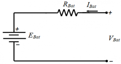
The simplified electrical model of the battery is illustrated in Figure 2 [27, 28].
Figure 2. Battery model
where,
${{V}_{Bat}}={{E}_{Bat}}+{{R}_{Bat}}{{I}_{Bat}}$ (1)
The battery capacity CBat can be calculated as follows [29]:
${{C}_{Bat}}={{C}_{0}}\frac{1.67(1+0.005\ \Delta T)}{1+0.67\left( \frac{{{I}_{Bat}}}{{{I}_{0}}} \right)}$ (2)
The state of charge of the battery is given as:
$SO{{C}_{Bat}}=\frac{Q}{{{Q}_{n}}}$ (3)
where,
$Q={{I}_{Bat}}\times t$ (4)
For the battery control, the latter is connected to the DC bus via a bi-directional buck-boost DC-DC converter, as shown in Figure 3.
Figure 3. Battery control using a conventional PI controller
3.2 Modeling of the supercapacitor
Supercapacitor is an electrical energy storage device, which is also referred to as an ultracapacitor or electrochemical capacitor, stores electric energy in an electric field. Modeling of a supercapacitor involves developing a mathematical model that represents the electrical behavior of the device.
To manage the remaining battery voltage and regulate battery charging, a battery control system is implemented. The exchange of power between the battery and the DC bus is possible through a bidirectional buck-boost converter that can be controlled.
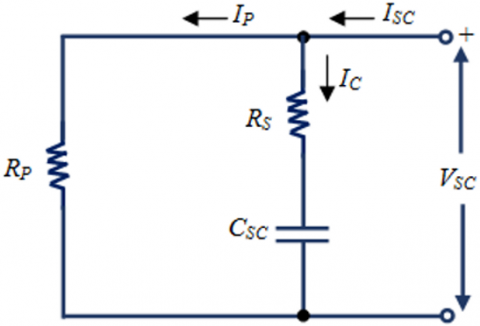
The process of modeling ultracapacitors (UCs) involves creating a series RC circuit that comprises an equivalent capacitance (Cs) and a series resistor (Rs). The series resistor represents the energy loss that occurs during the charging and discharging of the capacitor. To factor in the impact of cell-balancing intervention and energy loss that results from capacitor self-discharge, an equivalent resistance (Rp) is connected in parallel to the series RC circuit. This model is illustrated in Figure 4 [30].
Figure 4. Supercapacitor model
The electrical behavior of a supercapacitor can be described by a set of differential equations that govern the charge and discharge of the device. These equations relate the voltage, current, and capacitance of the supercapacitor, and take into account the internal resistance and capacitance of the device, as well as any external loads connected to the device.
Generally, the modeling of a supercapacitor is important for predicting its electrical and thermal behavior, and for optimizing its design and performance. By using these models, we can better understand the behavior of supercapacitors under different operating conditions and design them for specific applications, such as in energy storage systems for electric vehicles, renewable energy systems, and other high-power applications.
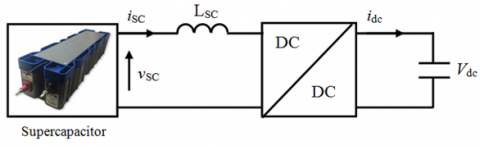
Figure 5. Supercapacitor electrical model with DC-DC converter
The supercapacitor, also referred to as an ultra-capacitor; is characterized by low series resistance, significant equivalent capacitance and a large number of charge/discharge cycles permitting a prolonged service duration. A capacitor stores energy via a static charge, as contrasted with an electrochemical reaction [30]. Figure 5 shows the equivalent average electrical model, a DC-DC buck-boost converter and a choke filter are associated with the supercapacitor tank as a means to adapt the voltage levels between the DC-DC converter and supercapacitor [31].
The power management strategy is formulated by assigning specific roles to each component of the hybrid power source. The supercapacitor is tasked with fulfilling the peak power demands, while the battery helps in meeting the transient power demand by regulating its state-of-energy. The photovoltaic panel system, with its slow dynamics, controls the state-of-charge of the battery.
${{C}_{SC}}\frac{d{{V}_{SC}}}{dt}=-{{I}_{SC}}$ (5)
The choke filter model is written as follows:
${{L}_{SC}}\frac{d{{I}_{SC}}}{dt}={{V}_{SC}}-{{u}_{m}}$ (6)
One possible way of describing the average model is as follows:
${{u}_{m}}={{m}_{SC}}{{V}_{dc}}$ (7)
${{i}_{m}}={{m}_{SC}}{{I}_{SC}}$ (8)
The supercapacitor tank can be modelled as follows [31].
3.3 The photovoltaic model
The PV model generally consists of several crucial parameters, such as the short-circuit current (Isc), open-circuit voltage (Voc), maximum power point voltage (Vmp), maximum power point current (Imp), and fill factor (FF). These parameters can be used to calculate the efficiency of the PV device, as well as its performance under different operating conditions [32].
The PV model is important for designing and optimizing PV systems for different applications, such as grid-tied or off-grid systems, as well as for predicting the energy yield of a PV system in a given location and climate. It can also be used to evaluate the performance of different PV technologies and to identify areas for further research and development.
There are several different PV models that can be used, ranging from simple empirical models to more complex physical models that take into account the detailed physics of the solar cell. The choice of model depends on the level of accuracy required and the available data and resources.
The modeling of solar photovoltaic has an extreme influence on optimal power delivery. A proper photovoltaic model ought to be highly sensitive to the change in irradiation and temperature levels, in an effort to replicate the exact I-V characteristics in a time-varying scenario.
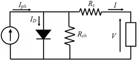
As depicted in Figure 6, the photovoltaic cell comprises a diode and a current source that are connected in anti-parallel with a series resistance.
Figure 6. Equivalent circuit of a solar cell with series and shunt resistance
The relationship between current and voltage in a single-diode cell can be expressed as follows [31, 32]:
${{I}_{PV}}={{I}_{ph}}-{{I}_{0}}\left( \exp \left( \frac{q\left( {{V}_{PV}}+{{R}_{s\bmod }}{{I}_{PV}} \right)}{AKT} \right)-1 \right)$ (9)
Figure 7. Current-voltage and power-voltage characteristics of the photovoltaic panel
From Figure 7, showing the photovoltaic characteristics; it can be noticed that these characteristics are not linear, thus, the presence of a controller is mandatory, in order to extract the maximum power obtained from the panel, leading to the optimal panel performance at different irradiation and temperature levels [33].
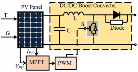
The implementation of the maximum power point tracking (MPPT) controller with a DC-DC boost converter is shown in Figure 8. The controlled boost converter serves as an interface between photovoltaic (PV) panels and the loads they are connected to. It transforms any input voltage within its operating range into a stable output voltage that is suitable for powering the load.
The proposed smart controller adapts the duty cycle of the boost converter based on input voltage and loading conditions such that it outputs a constant output voltage. A prototype system has been developed to verify the applicability and the integration of the proposed controller into automotive field.
Figure 8. MPPT Control with a boost converter
4.1 Designing and programming ANN models
Artificial Neural Network (ANN) is a novel computing technology in the field of computer science study and one of the studies of Artificial Intelligence. Pattern recognition, data analysis, and control are the most common applications for neural networks. Knowledge of the nervous system, particularly the human brain and its densely coupled neurons, inspired the central concept. Because of its high nonlinearity, massive volumes of data-parallel processing, and high robustness, artificial neural networks (ANN) are one of the methods that are suited for dealing with the internal relations of a complicated model [34].
To experimentally investigate artificial neural network-based power management for electric vehicles, a prototype system must be designed and implemented, followed by testing under different conditions. Suitable components must be selected based on their compatibility and suitability for the electric vehicle application, such as a PV panel, battery, supercapacitor, DC-DC converter, DC-AC inverter, and AC motor. The artificial neural network-based power management system would monitor the motor's power demand and optimize the power flow from the PV panel, battery, and supercapacitor to the DC bus link. Experiments should evaluate the system's performance under various conditions, and data collected during testing should be analyzed to assess the accuracy of the neural network's predictions and the effectiveness of the system in optimizing power flow [35].
4.2 Training base
4.2.1 Adapting measurements for neural network inputs
In order to simplify the neural network and process all potential values, we can utilize the numbering of variation intervals for the measured quantities as neural network inputs. The adaptation of measurements for neural network inputs is illustrated in Table 1.
Depending on the measurement of these chosen parameters and depending on the digitized intervals, the final structure of the neural network will be presented in the following section.
4.2.2 The final structure used
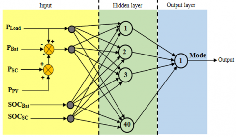
Figure 9 illustrates the ultimate architecture utilized as the training base, which is composed of three main components: (1) an input layer for independent variables, (2) one or more hidden layers, and (3) an output layer for the dependent variable.
Figure 9. Power management based neural network model architecture
Table 1. Adapting measurements for neural network inputs
|
Size measured |
Variation interval |
Interval numbering (specification of neural network inputs) |
|
PLoad |
PLoad< 0 |
-1 |
|
PLoad = 0 |
0 |
|
|
PLoad> 0 |
+1 |
|
|
PLoad-PSC-PBat-PPV |
< 0 |
-1 |
|
≥ 0 |
+1 |
|
|
SOCBat |
SOCBat≤30% |
1 |
|
80%≥ SOCBat> 25% |
2 |
|
|
90%≥ SOCBat> 60% |
3 |
|
|
SOCBat> 90% |
4 |
|
|
SOCSC |
SOCSC ≤30% |
1 |
|
90%≥ SOCSC> 30% |
2 |
|
|
90%≥ SOCSC> 60% |
3 |
|
|
SOCSC> 90% |
4 |
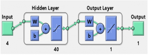
Figure 10. Power management based neural network model architecture on MATLAB Simulink
Designing a power management system using a neural network model on MATLAB Simulink involves several steps (Figure 10). In this case, we will provide a high-level overview of the process involved in developing a power management system using a neural network model in MATLAB Simulink [36].
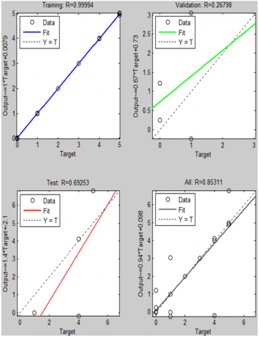
Figure 11. The obtained target based training process
The driving modes operation used in the power management algorithm are listed in Table 2, those modes are already mentioned below.
Table 2. Neural network outputs
|
Mode |
Mode 0 |
0 |
|
Mode 1 |
1 |
|
|
Mode 2 |
2 |
|
|
Mode 3 |
3 |
|
|
Mode 4 |
4 |
|
|
Mode 5 |
5 |
Table 3. Training table
|
No |
PLoad |
PLoad-PSC-PBat-PPV |
SOCBat |
SOCSC |
Mode |
|
1 |
-1 |
-1 |
1 |
1 |
5 |
|
2 |
-1 |
-1 |
2 |
2 |
4 |
|
3 |
-1 |
-1 |
3 |
3 |
4 |
|
4 |
-1 |
-1 |
4 |
4 |
4 |
|
5 |
-1 |
+1 |
1 |
1 |
5 |
|
6 |
-1 |
+1 |
2 |
2 |
4 |
|
7 |
-1 |
+1 |
3 |
3 |
4 |
|
8 |
-1 |
+1 |
4 |
4 |
4 |
|
9 |
0 |
-1 |
1 |
1 |
5 |
|
10 |
0 |
-1 |
2 |
2 |
0 |
|
11 |
0 |
-1 |
3 |
3 |
0 |
|
12 |
0 |
-1 |
4 |
4 |
0 |
|
13 |
0 |
+1 |
1 |
1 |
5 |
|
14 |
0 |
+1 |
2 |
2 |
0 |
|
15 |
0 |
+1 |
3 |
3 |
0 |
|
16 |
0 |
+1 |
4 |
4 |
0 |
|
17 |
+1 |
-1 |
1 |
1 |
2 |
|
18 |
+1 |
-1 |
2 |
2 |
2 |
|
19 |
+1 |
-1 |
3 |
3 |
1 |
|
20 |
+1 |
-1 |
4 |
4 |
1 |
|
21 |
+1 |
+1 |
1 |
1 |
1 |
|
22 |
+1 |
+1 |
2 |
2 |
1 |
|
23 |
+1 |
+1 |
3 |
3 |
1 |
|
24 |
+1 |
+1 |
4 |
4 |
3 |
In this study, the following operation modes of the electric vehicle are proposed [30]:
Shutdown mode (mode 0): This mode is activated when the electric vehicle is completely turned off. The electrical system is deactivated and all vehicle functions are out of service.
Starting mode (mode 1): This mode is activated when the driver turns on the electric vehicle.
Acceleration mode (mode 2): This mode is activated when the driver presses the accelerator pedal, and the electric motor increases the vehicle's speed.
Operation at nominal speed (mode 3): This mode is activated when the vehicle is moving at a steady speed, and the electric motor is maintaining that speed.
Constant speed or cruise mode (mode 4): This mode is activated when the driver sets the vehicle to maintain a constant speed, often used during highway driving.
Deceleration or braking mode (mode 5): This mode is activated when the driver applies the brakes or reduces the accelerator pedal, and the electric motor slows down the vehicle. In some electric vehicles, this mode can also regenerate energy back into the battery.
4.2.3 Training table
Table 3 summarizes the training table for learning method based on neural networks for the energy management of an electric vehicle which will be implemented under MATLAB/Simulink.
Power management strategies play a critical role in determining the performance, efficiency, and range of electric vehicles (EVs). One approach to power management in EVs is to use artificial neural networks (ANNs), which are a type of machine learning algorithm that can learn to make predictions and decisions based on input data [38, 39].
An ANN-based power management strategy for EVs involves training a neural network using data on the vehicle's current state, such as battery charge level, vehicle speed, and driving conditions, as well as information on the desired performance, such as maximum speed or range. The neural network can then predict the optimal power distribution between the battery and the electric motor to achieve the desired performance while minimizing energy consumption.
The following are some of the benefits of using an ANN-based power management strategy in EVs [40]:
- Improved Efficiency: by optimizing power distribution, an ANN-based power management strategy can improve the efficiency of an EV, leading to better range and lower energy consumption.
- Improved Performance: an ANN-based power management strategy can optimize power distribution to improve the performance of an EV, such as acceleration and top speed, without compromising efficiency.
- Flexibility: ANNs can adapt to changing driving conditions and driver behavior, making the power management strategy more flexible and responsive to the needs of the driver.
- Predictive Maintenance: ANNs can also be used to predict battery health and performance, allowing for proactive maintenance and replacement to ensure optimal performance and safety.
Overall, an ANN-based power management strategy is a promising approach to improving the performance and efficiency of electric vehicles, and it has the potential to further improve as machine learning algorithms continue to evolve [41].
Figure 12. Power management flowchart
Efficient energy management strives to maximize the efficiency of powertrain components while preserving a sufficient quantity of energy in storage devices. Furthermore, energy consumption must be managed without compromising vehicle performance, which can only be accomplished by implementing an effective control method [42].
The control algorithm focuses on operating each vehicle component with optimal energy, as well as recovering as much potential energy as possible during braking while keeping the state of charge of the energy storage systems within a predetermined range. The suggested energy management flowchart, shown in Figure 12, explains how the driving modes are selected based on the previously mentioned driving modes.
To verify the effectiveness and dynamic performance of the proposed strategy, MATLAB/Simulink software was employed to conduct numerical simulations on an electric vehicle powered by a permanent magnet synchronous motor (PMSM) under different load conditions.
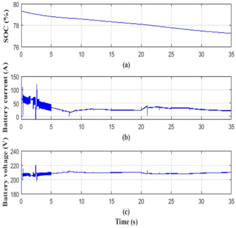
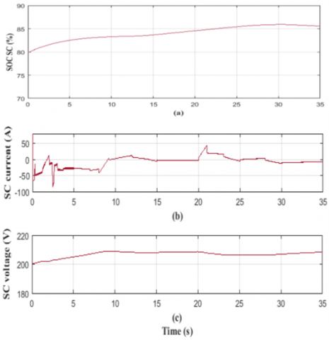
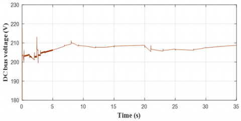
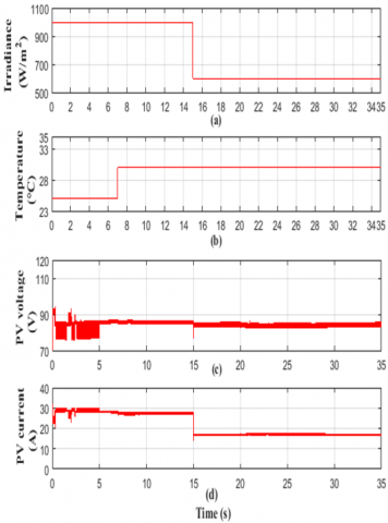
Figures 13 (a), (b) and (c) show the voltage, the current and the state of charge of the main source of energy, its dynamics follow the changes in the reference speed. The voltage, current and the state of charge of the supercapacitor are shown in Figures 14 (a), (b) and (c) respectively, similarly to the battery the changes correspond to the energy demand of the motor. Figure 15 illustrates the DC bus voltage which is about 210V, it only changes when the energy demand gets higher in t=2 s. Figures 16 (a) and (b) are dedicated to the photovoltaic voltage and current variations; it is noticeable that the generated power from the photovoltaic panel is lower than that of the other energy storage systems because it is only needed in critical battery discharge.
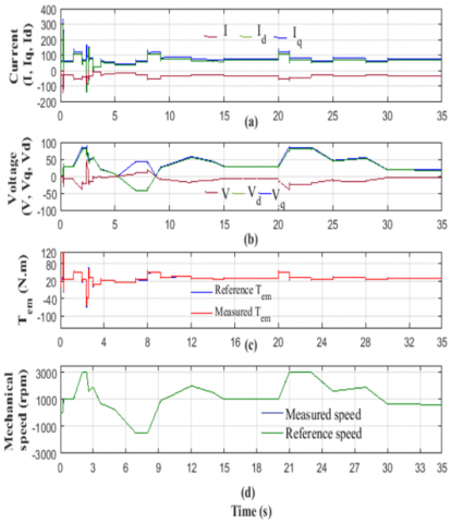
Figure 17 illustrates the performance of the control strategy applied to the PMSM motor. In Figure 17 (d), the speed response to reference variations is displayed, demonstrating good dynamics and effective reference tracking. The dynamic of the electromagnetic torque is shown in Figure 17 (c), which is crucial for vehicle performance. The ability to produce greater torque leads to faster acceleration, and the measured torque follows its reference even with sudden changes, indicating the effectiveness of the control technique implemented in the system.
From Figure 17, it can be observed that the process of regulating speed causes significant fluctuations in torque and current, which are influenced by changes in speed. However, when bus voltage changes are taken into account during the speed regulation period, Figure 17 (a) and (c) demonstrate a substantial reduction in current and torque fluctuations.
Figure 13. Battery characteristics, (a) Global state of charge of the battery, (b) Battery current, (c) Battery voltage
Figure 14. Supercapacitor characteristics, (a) Global state of charge of the supercapacitor, (b) Supercapacitor current, (c) Supercapacitor voltage
Figure 15. DC bus voltage
Figure 16. Photovoltaic panel characteristics, (a) Solar irradiation, (b) temperature variation, (c) Photovoltaic voltage and (d) Photovoltaic current
Figure 17. Motor performance considering speed variation of vector control strategy, (a) current components, (b) voltage components, (c) Torque response to the changes in the reference torque drive, (d) speed regulation
Figure 18. Power management of the hybrid setup under varying vehicle speed
These results indicate that the speed modifier with bus voltage regulation effectively minimizes torque and current fluctuation during speed regulation, leading to improved output speed-torque characteristics of the motor. Figure 17 (b) illustrates the response of voltage components to load variations, and it is apparent that the voltage components are effectively decoupled with dynamic changes that correspond to variations in acceleration.
Considering that the load power is obtained by summing the power generated from the photovoltaic panel and the other energy storage systems, namely the battery and supercapacitor, the power management applied to the electric vehicle is depicted in Figure 18. The simulation results are in agreement with the theoretical characteristics discussed earlier, and the various driving modes are clearly visible. For instance, at t=0 s when the power demand is at its highest, the battery deeply discharges, and the supercapacitor compensates for the lost energy from the battery. During the low power generation mode, the battery alone powers the motor. From t=2 s, when the power demand is medium, all energy storage systems work together to meet the load's power demand. At t=12 s, the regenerative braking mode begins, and the motor acts as a generator, charging the battery.
The obtained simulation results for the proposed hybrid system demonstrate that the integration of the photovoltaic panel in the power system storage of electric vehicle can protect the life cycle of the battery and the supercapacitor and absorbs the fluctuation in the injected energy and supplies the load as a second energy source in any fault has appeared.
The work reported in this paper describes a hybrid energy system for integrated photovoltaic vehicles that incorporates a battery as the primary storage device and a supercapacitor as a backup. This configuration improves the solar vehicle by reducing peak current effects on the batteries. Thus, extending battery life, and limiting DC bus voltage changes. A power management strategy based on neural networks was put forward to maintain DC bus voltage stability regardless of motor speed or solar irradiation and to enhance the driving range. The effectiveness of the proposed energy management strategy was evaluated by means of MATLAB simulation. The results demonstrate that combining a supercapacitor with a battery in solar cars can extend the limited driving range while also increasing the speed.
However, the effectiveness of ANNs for power management of an EV depends on various factors, such as the quality of input data, the architecture of the neural network, and the training method used. Additionally, the use of ANNs requires significant computational resources, which may be a limitation for onboard implementation in real-time.
While ANNs have shown promising results for power management of EVs, further research is needed to fully understand their potential and limitations in this application. Nonetheless, the use of ANNs for power management of EVs is a promising avenue that could significantly improve the efficiency and range of these vehicles.
In conclusion, the limitations and future research directions of power management using artificial neural networks with multiple energy sources should be considered. Limitations may include data availability, methodology, and ANN architecture. Future research could include the incorporation of other energy storage devices, emerging technologies, advanced ANN architectures, data processing techniques, and optimization algorithms. Additionally, exploring the impact of different driving conditions, traffic scenarios, and climate conditions on the power management system's performance could be beneficial. Addressing these limitations and exploring future research directions can contribute to the development of more efficient and sustainable power management systems for electric vehicles.
|
ANN |
Artificial Neural Network |
|
AC |
Alternative current |
|
EV |
Electric vehicle |
|
DC |
Direct current |
|
DSP |
Digital signal processing |
|
DSPACE |
Digital signal processing and control engineering |
|
FF |
Fill factor |
|
MOSFET |
Metal oxide semiconductor field effect transistor |
|
MPPT |
Maximum Power Point Tarking |
|
PMSM |
Permanent Magnet Synchronous Motor |
|
PV |
Photovoltaic |
|
PWM |
Pulse Width Modulation |
|
SC |
Supercapacitor |
|
I |
Operating current, A |
|
I0 |
The reverse saturation current, A |
|
IBat |
Battery current, A |
|
ID |
Diode Current, A |
|
Imp |
maximum power point current, A |
|
Iph |
The light-generated current, A |
|
ISC |
Supercapacitor current, A |
|
Isct |
Short-circuit current, A |
|
Ish |
The photo-generated current, A |
|
kB |
The Boltzmann constant |
|
n |
The diode ideality factor |
|
PBat |
Battery power, V |
|
PLoad |
Power load, W |
|
PPV |
Photovoltaic power, W |
|
PSC |
Supercapacitor power, W |
|
Q |
The maximum possible charge that can be stored in a battery, C |
|
q |
The charge of an electron, C |
|
Qn |
Thenominal capacity, C |
|
RS |
The series resistance, Ω |
|
Rsh |
The shunt resistance, Ω |
|
SOCBat |
State of charge of the batterye, % |
|
SOCSC |
State of charge of the supercapacitor, % |
|
t |
The time, s |
|
Tc |
The cell temperature, °C |
|
V |
Operating voltage,V |
|
VBat |
Battery voltage, V |
|
Vdc |
DC link voltage, V |
|
Vmp |
Maximum power point voltage, V |
|
Voc |
Open-circuit voltage, V |
|
VSCt |
Supercapacitor voltage, V |
[1] Sadik Croock, M., Salman Mahmood, S. (2022). Management system of smart electric vehicles using software engineering model. International Journal of Electrical and Computer Engineering Systems, 13(5): 369-377. https://doi.org/10.32985/ijeces.13.5.5
[2] Elkasrawy, M., Hassan, A., Abdellatif, S., Ebrahim, G., Ghali, H. (2022). Prototyping design and optimization of smart electric vehicles/stations system using ANN. International Journal of Electrical and Computer Engineering Systems, 13(6): 485-491. https://doi.org/10.32985/ijeces.13.6.8
[3] Alinejad, M., Rezaei, O., Kazemi, A., Bagheri, S. (2021). An optimal management for charging and discharging of electric vehicles in an intelligent parking lot considering vehicle owner's random behaviors. Journal of Energy Storage, 35: 102245. https://doi.org/10.1016/j.est.2021.102245
[4] Ahmad, F., Khalid, M., Panigrahi, B.K. (2021). An enhanced approach to optimally place the solar powered electric vehicle charging station in distribution network. Journal of Energy Storage, 42: 103090. https://doi.org/10.1016/j.est.2021.103090
[5] Huo, D., Meckl, P. (2022). Power management of a plug-in hybrid electric vehicle using neural networks with comparison to other approaches. Energies, 15(15): 5735. https://doi.org/10.3390/en15155735
[6] Panichtanakom, S., Chalermyanont, K. (2022). Electric energy management for plug-in electric vehicles charging in the distribution system by a dual cascade scheduling algorithm. International Journal of Electrical and Computer Engineering Systems, 13(1): 63-75. https://doi.org/10.32985/ijeces.13.1.7
[7] Ordóñez, F., Morales, C., López-Villada, J., Vaca, S. (2018). Assessment of the energy gain of photovoltaic systems by using solar tracking in equatorial regions. Journal of Solar Energy Engineering, 140(3): 031003. https://doi.org/10.1115/1.4039095
[8] Lopes, F.M., Silva, H.G., Salgado, R., Cavaco, A., Canhoto, P., Collares-Pereira, M. (2018). Short-term forecasts of GHI and DNI for solar energy systems operation: assessment of the ECMWF integrated forecasting system in southern Portugal. Solar Energy, 170: 14-30. https://doi.org/10.1016/j.solener.2018.05.039
[9] Firozjaei, M.K., Nematollahi, O., Mijani, N., Shorabeh, S.N., Firozjaei, H.K., Toomanian, A. (2019). An integrated GIS-based Ordered Weighted Averaging analysis for solar energy evaluation in Iran: Current conditions and future planning. Renewable Energy, 136: 1130-1146. https://doi.org/10.1016/j.renene.2018.09.090
[10] Brito, M.C., Santos, T., Moura, F., Pera, D., Rocha, J. (2021). Urban solar potential for vehicle integrated photovoltaics. Transportation Research Part D: Transport and Environment, 94: 102810. https://doi.org/10.1016/j.trd.2021.102810
[11] Katuri, R., Gorantla, S. (2019). Design and simulation of a controller for a hybrid energy storage system based electric vehicle. Mathematical Modelling of Engineering Problems, 6(2): 203-216. https://doi.org/10.18280/mmep.060208
[12] Pillot, B., Muselli, M., Poggi, P., Haurant, P., Hared, I. (2013). Solar energy potential atlas for planning energy system off-grid electrification in the Republic of Djibouti. Energy Conversion and Management, 69: 131-147. https://doi.org/10.1016/j.enconman.2013.01.035
[13] Saleeb, H., Sayed, K., Kassem, A., Mostafa, R. (2019). Power management strategy for battery electric vehicles. IET Electrical Systems in Transportation, 9(2): 65-74. https://doi.org/10.1049/iet-est.2018.5026
[14] Rutten, B., Cobbenhagen, R. (2019). Future trends in electric vehicles enabled by internet connectivity, solar, and battery technology. Automotive Systems and Software Engineering: State of the Art and Future Trends, 323-346. https://doi.org/10.1007/978-3-030-12157-0_15
[15] Millo, F., Rolando, L., Tresca, L., Pulvirenti, L. (2023). Development of a neural network-based energy management system for a plug-in hybrid electric vehicle. Transportation Engineering, 11: 100156. https://doi.org/10.1016/j.treng.2022.100156
[16] Heinrich, M., Kutter, C., Basler, F., Mittag, M., Alanis, L.E., Eberlein, D., Wirth, H. (2020). Potential and challenges of vehicle integrated photovoltaics for passenger cars. Presented at the 37th European PV Solar Energy Conference and Exhibition, 7(11): 4229.
[17] Lemian, D., Bode, F. (2022). Battery-Supercapacitor Energy Storage Systems for Electrical Vehicles: A Review. Energies, 15(15): 5683. https://doi.org/10.3390/en15155683
[18] Araria, R., Negadi, K., Marignetti, F. (2019). Design and analysis of the speed and torque control of IM with DTC based ANN strategy for electric vehicle application. TecnicaItaliana-Italian Journal of Engineering Science, 63(2-4): 181-188. https://doi.org/10.18280/ti-ijes.632-410
[19] Naseri, F., Farjah, E., Ghanbari, T. (2016). An efficient regenerative braking system based on battery/supercapacitor for electric, hybrid, and plug-in hybrid electric vehicles with BLDC motor. IEEE Transactions on Vehicular Technology, 66(5): 3724-3738. https://doi.org/10.1109/TVT.2016.2611655
[20] Gharibeh, H.F., Yazdankhah, A.S., Azizian, M.R. (2020). Energy management of fuel cell electric vehicles based on working condition identification of energy storage systems, vehicle driving performance, and dynamic power factor. Journal of Energy Storage, 31: 101760. https://doi.org/10.1016/j.est.2020.101760
[21] Han, Y.M., Geng, Z.Q., Zhu, Q.X. (2016). Energy optimization and prediction of complex petrochemical industries using an improved artificial neural network approach integrating data envelopment analysis. Energy Conversion and Management, 124: 73-83. https://doi.org/10.1016/j.enconman.2016.07.002
[22] Bouradi, S., Negadi, K., Araria, R., Marignetti, F. (2022). Z-source inverter for energy management and vector control for electric vehicle based pmsm z-source inverter for energy management and vector control for electric vehicle based pmsm. Journal Européen des Systèmes Automatisés, 53(6): 1883-1892. https://doi.org/10.18280/jesa.530614
[23] Zhou, T., Francois, B. (2009). Modeling and control design of hydrogen production process for an active hydrogen/wind hybrid power system. International Journal of Hydrogen Energy, 34(1): 21-30. https://doi.org/10.1016/j.ijhydene.2008.10.030
[24] Lhomme, W., Delarue, P., Barrade, P., Bouscayrol, A., Rufer, A. (2005). Design and control of a supercapacitor storage system for traction applications. In Fourtieth IAS Annual Meeting. Conference Record of the 2005 Industry Applications Conference, Hong Kong, China, IEEE, pp. 2013-2020. https://doi.org/10.1109/IAS.2005.1518724
[25] Katuri, R., Gorantla, S. (2018). Modelling and analysis of a hybrid controller applied to the ultracapacitor based solar powered electric vehicle. Modelling, Measurement and Control A, 91(3): 114-122. https://doi.org/10.18280/mmc_a.910303
[26] Mohamed, A.A., Berzoy, A., Mohammed, O.A. (2016). Design and hardware implementation of FL-MPPT control of PV systems based on GA and small-signal analysis. IEEE Transactions on Sustainable Energy, 8(1): 279-290. https://doi.org/10.1109/TSTE.2016.2598240
[27] Kofinas, P., Doltsinis, S., Dounis, A.I., Vouros, G.A. (2017). A reinforcement learning approach for MPPT control method of photovoltaic sources. Renewable Energy, 108: 461-473. https://doi.org/10.1016/j.renene.2017.03.008
[28] Ramineni, P., Pandian, A. (2021). Study and investigation of energy management techniques used in electric/hybrid electric vehicles. Journal Européen des Systèmes Automatisés, 54(4): 599-606. https://doi.org/10.18280/jesa.540409
[29] Vidhya, S.D., Balaji, M. (2019). Modelling, design and control of a light electric vehicle with hybrid energy storage system for Indian driving cycle. Measurement and Control, 52(9-10): 1420-1433. https://doi.org/10.1177/0020294019858212
[30] Katuri, R., Gorantla, S. (2018). Modelling and analysis of a hybrid controller applied to the ultracapacitor based solar powered electric vehicle. Modelling, Measurement and Control A, 91(3): 114-122. https://doi.org/10.18280/mmc_a.910303
[31] Essam Harby, M., Elzoghby, H., Elmasry, S., Elsamahy, A. (2020). Bidirectional control of electric vehicles based on artificial neural network considering owners convenience and microgrid stability. International Review of Automatic Control (IREACO), 13(6): 304-312. https://doi.org/10.15866/ireaco.v13i6.19841
[32] Djelamda, I., Bouchareb, I. (2022). Li-Ion battery fault diagnosis dedicated to electric vehicles by neural network pattern recognition. Mathematical Modelling of Engineering Problems, 9(1): 144-149. https://doi.org/10.18280/mmep.090118
[33] Azizi, I., Radjeai, H. (2018). A new strategy for battery and supercapacitor energy management for an urban electric vehicle. Electrical Engineering, 100(2): 667-676. https://doi.org/10.1007/s00202-017-0535-1
[34] Feng, N., Ma, T., Chen, C. (2022). Fuzzy energy management strategy for hybrid electric vehicles on battery state-of-charge estimation by particle filter. SN Applied Sciences, 4(10): 256. https://doi.org/10.1007/s42452-022-05131-8
[35] Berkani, A., Negadi, K., Allaoui, T., Mezouar, A., Denai, M. (2019). Imposed switching frequency direct torque control of induction machine using five level flying capacitors inverter. European Journal of Electrical Engineering, 21(2): 241-248. https://doi.org/10.18280/ejee.210217
[36] Wu, J.D., Hsieh, C.Y., Luo, W.J. (2021). Sound visualization and convolutional neural network in fault diagnosis of electric motorbike. Traitement du Signal, 38(6): 1819-1827. https://doi.org/10.18280/ts.380626
[37] Fernandez, J.A., Riu, D., Bacha, S., Paupert, M., Hably, A. (2016). Real-time plug-in electric vehicle charging strategies for current and voltage unbalance minimization. Journal Européen des Systèmes Automatisés, 49(3): 271-298. https://doi.org/10.3166/JESA.49.271-298
[38] Zheng, W., Wang, H.B., Zhang, Z.M., Li, N., Yin, P.H. (2019). Multi-layer feed-forward neural network deep learning control with hybrid position and virtual-force algorithm for mobile robot obstacle avoidance. International Journal of Control, Automation and Systems, 17: 1007-1018. https://doi.org/10.1007/s12555-018-0140-8
[39] Sayed, K., Abdel-Khalek, S., Zakaly, H.M., Aref, M. (2022). Energy management and control in multiple storage energy units (battery–supercapacitor) of fuel cell electric vehicles. Materials, 15(24): 8932. https://doi.org/10.3390/ma15248932
[40] Lu, R., Hong, S.H., Yu, M. (2019). Demand response for home energy management using reinforcement learning and artificial neural network. IEEE Transactions on Smart Grid, 10(6): 6629-6639. https://doi.org/10.1109/TSG.2019.2909266
[41] Wang, S., Qin, D. (2020). Online control strategy for plug-in hybrid electric vehicles based on an improved global optimization algorithm. Applied Sciences, 10(23): 8352. https://doi.org/10.3390/app10238352
[42] Zhang, X., Liu, Y., Zhang, J., Dai, W., Liu, Z. (2017). A fuzzy neural network energy management strategy for parallel hybrid electric vehicle. In 2017 9th International Conference on Modelling, Identification and Control (ICMIC), Kunming, China, IEEE, pp. 342-347. https://doi.org/10.1109/ICMIC.2017.8321666