Mohammed B. Mahmood*![]() | Jassim M. Abdul-Jabbar
| Jassim M. Abdul-Jabbar![]()
© 2023 IIETA. This article is published by IIETA and is licensed under the CC BY 4.0 license (http://creativecommons.org/licenses/by/4.0/).
OPEN ACCESS
This paper aims to build an efficient, secure, and reliable Industrial-IoT system for regions with slow, unreliable Internet connections to maintain the minimum requirements for industrial processes and guarantee production sustainability. In this paper, a remote monitoring and control system is established practically using KEPServerEX. The communication between the client and the server is accomplished through the internet using Fiber to the Home (FTTH) architecture with a dedicated public IP address on the server side. At the same time, 3G mobile data and FTTH have been used on the Client side. Open Platform Communications United Architecture (OPC UA) transfers automation data between the client and the server through the internet. The hardware devices are connected to the server through Ethernet cables. A monitoring HMI is programmed and interfaced with the KEPServerEX on the client side, which is located far away from the server area. This paper introduces an innovative method to achieve dual-link connections between the OPC UA Server and the Remote OPC UA Client. A redundant Internet link is used in parallel with the other link to provide more reliability, availability, and security to the system. The designed system sends an alarm to the client in case of detecting link communication failure, link transmission delay, or malicious data injection into the system. The results show that the client can receive the alarm within a time delay between 200 to 300 ms.
industrial IoT, OPC UA, network redundancy, KEPServerEx, digital voting, PLC
The increasing number of connected devices through the internet with various software and data types pulls the software designer to innovate new systems and software that guarantee easy negotiations and data transfer between devices. In industrial applications, the OPC Foundation produces a new protocol called Open Platform Communications United Architecture (OPC UA). The OPC UA provides a solution for heterogeneous devices to interact with each other in secure, reliable channels through private or public networks. The device interaction is known as the machine-to-machine (M2M) interaction. The OPC UA is not just a means of communication between devices. However, it is also used to transfer data from floor devices to the upper application layers using web services over the internet [1, 2]. The industrial applications and devices that interact through the internet are called Industrial IoT. The OPC UA can be assumed as the backbone protocol for industrial IoT applications, which guarantees the data transfer between multiple hardware vendors and software systems in a secure, reliable way [3, 4]. The OPC UA is assumed as a new version of the old OPC Classic by adding new features like address space architecture, data modeling, discovery functionalities, and security. To date, the OPC UA has covered many systems and machines and is the dominant process communication protocol in industrial applications. Because of the OPC UA address space, the data can be modeled to a specific communication protocol without any constraints and allow the information to be flown between heterogeneous systems [5].
A KEPServerEx is an industrial platform that allows various industrial automation devices to interact with each other by using a single source of industrial automation data. The platform's design allows users to connect, monitor, manage and control numerous automation devices and software applications through one intuitive user interface. KEPServerEX supports Operation Technology (OT) by using OPC UA communication protocol and supports Information Technology (IT) by using IT communication protocols (such as SNMP, ODBC, and web services) to provide users with a single source for industrial data [6].
This paper introduces an innovative method to achieve dual-link connections between OPC UA Server and the Remote OPC UA Client through the Internet. The critical factor for industrial IoT is how to collect the data from the physical layer efficiently and send the data that has been collected to the upper layer with a high data rate and low latency. The designed system redundancy has been done at the WAN level by depending on two different ISPs to send the same data through each ISP to improve the availability and reliability, then compare the received data within a limited time to prevent hackers from injecting malicious data. In general, on the factory side (server side), the Internet is more reliable than the client side because, on the server side, a business link with a public IP can be used. Therefore, on the server side, one or two internet service providers (ISPs) can be used depending on the application and availability of the ISPs on the factory work floor. On the client side, ISPs are less reliable than servers because they depend on mobile data or home ISP with no dedicated public IP. Therefore, using two ISPs on the client side is necessary to achieve high reliability and availability. However, from the point of data analysis, the same results are expected from both links on the Internet. In addition, physical devices and wires need to be installed with a new subscription account. Therefore, another internet link between the server and the client is achieved by connecting the client and the server using a local router to check the system's operability. The server is connected to one of the router's Ethernet ports, while the client is connected through another Ethernet port of the same router.
Several references are surveyed and studied to discover what has yet to be covered in the area of Industrial IoT. The references [7-14] focus on the redundancy in Industrial IoT systems. Those references introduce redundancy types in network communication layers and other area networks (LAN, WAN, and LPWAN). Table 1 indicates a summary of the studied and surveyed references and shows that all of the researched references have achieved both area network redundancy and packet redundancy, except two of them [8, 13], which have achieved area network redundancy only. In addition, most of them give their results throughout simulations except a single one [11] which deals with the practical system. Also, only reference [10] has focused on WAN redundancy, and reference [12] on LPWAN redundancy.
Meanwhile, all other references have focused on LAN redundancy. Regarding packet redundancy, no one has used packet redundancy at the application layer. It's worth noting that the present paper focuses on packet redundancy at the application layer on redundant WAN networks.
Table 1. Comparison between different references in the literature according to their contents
|
Author Name and Reference No. |
Area Network Redundancy |
|
The layer of Packet Redundancy |
|
Type of Work |
|||||
|
LAN |
WAN |
LPWAN |
Physical |
Data Link |
Network |
Transport |
Application |
Simulation |
Practical |
|
|
Rentschler et al. [7] |
Y |
|
|
|
Y |
|
|
|
Y |
|
|
Giorgetti et al. [8] |
Y |
|
|
|
|
|
|
|
Y |
|
|
Ferrari et al. [9] |
Y |
|
|
|
Y |
|
|
|
Y |
|
|
Popovic et al. [10] |
|
Y |
|
|
|
|
Y |
|
Y |
|
|
Lucas-Estañ et al. [11] |
Y |
|
|
|
Y |
|
|
|
|
Y |
|
Sanchez et al. [12] |
|
|
Y |
Y |
|
|
|
|
Y |
|
|
Dirgantoro et al. [13] |
Y |
|
|
|
|
|
|
|
Y |
|
|
Kiangala et al. [14] |
Y |
|
|
Y |
|
|
|
|
Y |
|
Notes: The Y symbol indicates the topics covered by the surveyed references.
3.1 Overall system description
The designed control system is based on Microsoft Windows 10 platform using KEPserverEX to transfer the data safely with a high level of security. KEPserverEX software is used depending on TLS and SSL security methods to ensure the messages' security, authentication, and encryption through different network topologies. Furthermore, a firewall is used at this level to get more protection. According to ISA 95 [15], the automation design achieves a fully integrated Industrial-IoT into one automation system distributed through different location areas. This connection method provides a powerful way to interface with other existing systems to make the monitoring, operation, maintenance, and problem diagnosis more fluent.
The main project idea is to use the concept of Industrial IoT in the regions that suffer from bad quality Internet Service Providers to maintain the minimum requirements for industrial processes and to guarantee production sustainability. In this paper, dual-link connections between the server and the client have been established to provide high reliability, availability, and security.
The idea of redundant paths (redundant data transmission) is based on two concepts according to the entity side (server or client). On the server side, the duplicated command has been executed at the PLC program level, while on the client side, the duplication has been performed at the HMI visualization level.
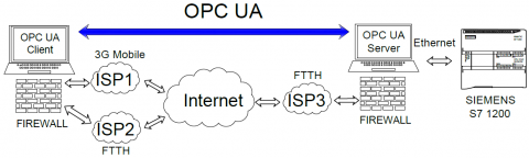
The dual-link connections between the OPC UA server and the remote OPC UA client are achieved using two ISPs are used on the client side, and another single ISP is used on the server side. In general, on the factory side (server side), the internet is more reliable than the client side because, on the server side, it should use the business link with a public IP. Therefore, on the server side, one can use one or two ISPs depending on the application and availability of the ISPs on the factory work floor. On the client side, ISPs may be less reliable than the server side because they may depend on mobile data or home internet service providers with no dedicated public IP and lower speed. Therefore, using two ISPs on the client side is necessary to achieve high reliability and availability. The client can access the server remotely since a dedicated public IP has been assigned. The proposed system has been done practically using two different ISPs. Two real communication channels are established between the client PC and the server PC through the Internet; therefore, the results shown in this paper are subject to real network effects like multi-layer, delay, and packet loss phenomena.
The Internet link through the FTTH will be called Link1, and the other link, which connects through 3G Mobile data, will be called Link2. Figure 1 shows the proposed system architecture.
Figure 1. Overall system architecture
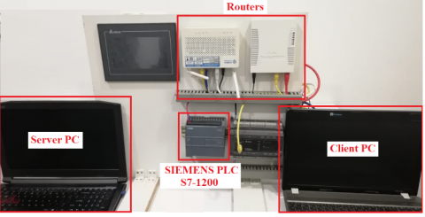
The physical system used during this work is shown in Figure 2. The used components are shown inside the red rectangles, which are: Server PC, Client PC, Siemens S7-1200 PLC, and routers.
Figure 2. A view of the hardware devices managed in the case study
3.2 Applicability of the designed system
This project applies to remote industrial automation systems, especially for controlling and operating critical parts in any industrial plant. In general, the designed system can serve in two different scenarios. In the first scenario, when giving an ignition command to a plant to start or stop working (or for any critical devices), the signal should come through two different ISPs within a specified time interval (depending on the network time delay). If an order is received only from one path and the same command is not received from the other path within the specified time interval, the system will initiate an alarm to inform the operator that one way has failed to take action. The second scenario for the alarm signal is when it is received at least from one path, it will initiate an alarm indication to inform the operator that this alarm has come from a single direction or both. This method of organization provides robustness, availability, reliability, and security for our designed system. The two scenarios are based on the digital voting principle. Even though OPC UA is designed for high security, availability, and redundancy architecture, there is a problem in the regions with slow, unreliable Internet connections due to the discontinuity in the Internet service provided by the ISPs. The time required to reconfigure the communication channel between the client and server depends on the disconnection time plus the reconfiguration time between the client and the server. For this reason, this paper focuses on solving the Internet discontinuity issue by depending on redundant ISP. In addition, the redundant ISP has been exploited to increase security by initiating an alarm that sends from the server to the client machine, monitored by an operator to detect any data injected by an intruder. The malicious data can be detected because it will be only received from one communication link and not from the other within a limited time unless the intruder has full knowledge of the system configuration and can send the data on both communication links. However, the system is still protected by OPC UA security.
3.3 The use of the digital voting principle in the designed system
Output action according to the voting algorithm. In general, digital voting is used with the input signals coming from sensors. In this project, the digital voting principle has also been exploited with some critical commands initiated by the operator-controlling device (HMI or Workstation) that works remotely through the Internet. Therefore, two out of two (2oo2) and one out of two (1oo2) have been considered. 2oo2 means the output is ON when the inputs are both ON. 1oo2 means the result is ON when at least one input is ON or both. Digital voting can affect the system in two ways: to reach a specific Safety Integrity Level (SIL). Secondly, to achieve a certain cost reduction by preventing the spurious shutdown of the plant.
To explain the critical situation that depends on 2oo2. Suppose the system only receives a command from one path during a predefined time interval (determined depending on the available internet quality and reliability). It does not receive the same order from the other path within that time interval. In that case, there will be an alarm on the MHI at the Client side to do an action. In general, Industrial IoT needs a high level of reliability and availability of the Internet link. A redundant internet link is always required to increase the system's reliability and availability. Unlike the proposed work in this paper, the redundant link is usually considered a standby and can only be used if the other connection is lost.
3.4 Alarm activating and deactivating procedures for ON/OFF test
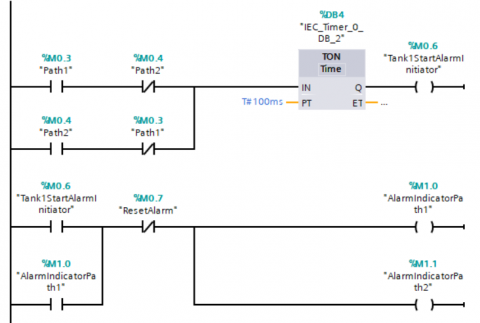
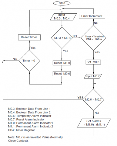
Figure 3 shows the proposed alarm activating and deactivating procedures for the ON/OFF process. The ladder diagram of Figure 3 has two functions. Firstly, it sets the maximum allowable time delay between data from the two links. Secondly, it activates an alarm if the time delay exceeds the maximum allowable delay. The alarm can be initiated due to the time delay between the data coming from the two links or one is disconnected. If the alarm is initiated due to a time delay, a reset button shall be activated to reset the alarm manually. However, if the alarm is initiated due to a broken link, it will not reset until that link is fixed and the data is received again from that link. M0.3 is dedicated to the Boolean signal coming from Link1, and M0.4 is to the Boolean signal coming from Link2. The first two lines of the ladder diagram of Figure 3 show an Exclusive OR (XOR) relation between M0.3 and M0.4. The output of the XOR will be logic “1” only when the two input values are different (M0.3 and M0.4). The output of the XOR is fed to the input of the timer register “IEC_Timer_0_DB_2”. The timer starts counting when its input feed is logic “1”, which happens when there is a difference in the value of the data coming from the two different links. If the data difference continues for more than 100 ms, then the timer output (M0.6) will be activated to logic “1”. The M0.6 can activate the alarm indicators (M1.0) and (M1.1), the (M1.0) is the alarm indicator transmitted through Link1, and (M1.1) is the alarm indicator transmitted through Link2. Once the alarm is activated, it will not go to deactivation mode again unless a manual reset button (M0.7) is activated manually. The alarm indicator cannot be deactivated once activated because a latch property is used, as shown in the last line in Figure 3. A flowchart is plotted to give a more precise idea, as shown in Figure 4.
Figure 3. PLC Ladder diagram program for alarm activating and deactivating procedures for the digital ON/OFF process
Figure 4. Flow chart for alarm activating and deactivating procedures for the digital ON/OFF process
4.1 Clint server connection test through two different internet service providers
Two scenarios are used in this work to check the connection of Round-Trip Time (RTT) between the client and server PCs through the Internet.
In the first scenario, the two PCs are connected to the FTTH ISP based on fiber optic cable. The internet service speed is 27 Mbps, according to the acquired reading from the fast.com site. Using the PC1 Command Prompt, PC2 has been pinged. The average RTT is found to be 5 ms. by repeating the previous steps by sending a ping from PC2 to PC1. The average RTT is then found to be 7 ms.
In the second scenario, the first PC is connected to the same ISP as in scenario one, whereas the second is connected to an ISP based on a 3G mobile system. The speed of the internet service provided by the 3G mobile system is 3.8 Mbps, according to the acquired reading from the fast.com site. The same procedures of scenario one are used for scenario 2. The average RTT is 223 ms and 189 ms, respectively. The big difference in the time delay comes from the 3G mobile Internet service being much slower than the Internet based on fiber optics.
4.2 Client-server tags testing
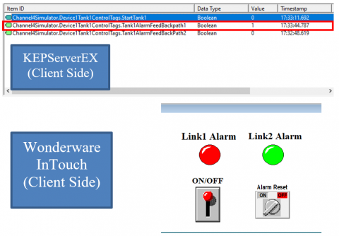
A ladder is programmed at the server side using the PLC ladder diagram to test the designed system program, as shown in Figure 3. The SIMATIC S7-1200 PLC interacts with the KEPServerEX Tags, which come from two different links. Figures 5 and 6 show two cases when the state of the control ON/OFF button on the client side changed from “0” to “1”, respectively. The ON/OFF button controller has been configured on the client side using Wonderware InTouch software. The upper part of Figures 5 and 6 shows a portion of the KEPServerEX workspace where the communicating tags are displayed. The fields of this portion are: the Item ID field contains the tag names; the Data Type field contains the type of the transmitted data; the Value field contains the current value of the tags; the Timestamp field contains the timestamp at which the tag value is updated and the Quality which contains the state of the link between the client and the server. Good Quality means a communication channel between the client and the server is currently available. The lower part of the figures shows a visual ON/OFF button at the remote OPC UA client.
Figure 5. System test for ON/OFF button from remote OPC UA client when OFF state is set
Figure 6. System test for ON/OFF button from remote OPC UA client when ON state is set
Figure 5 shows two zero values for the signals coming from Link2 and Link1 repeatedly since the ON/OFF button at the client side is set to the OFF state. Figure 6 shows one value for the signals coming from Link2 and Link1 repeatedly since the ON/OFF button at the client side is set to the ON state.
At the client side, after repeatedly turning the switch ON and OFF, the time difference between data on Link1 and Link2 at the server side is found to be zero because the scan rate of the server is 100 ms. The two streams of data are received within 10 ms.
During the test, the maximum allowable time delay between the signals coming from the links is set to 100 ms. Through the PLC, we can change the permissible time delay by changing the time delay function according to the RTT of the two communication links.
Generally, Sending data in two copies through the Internet increases network traffic. Still, in this case, the effect of the redundant link on the network is very low since only the critical data (Tags) will be sent between the server and the client. Furthermore, the bandwidth required to transmit such automated data is very low because the tags hold Boolean or Real Number data. In addition, the designed system scan rate is 100 ms, meaning only the updated data will be sent each 100 ms.
4.3 Alarm initiation test
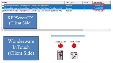
Figure 7 shows that Link1 is disconnected since it activates value “1” at the timestamp (17:33:44.787). The value “1” is only set when the alarm comes from Link1. That is because the client machine is configured to give logic “1” when there is a bad link connection (link disconnecting).
Figure 7. Alarm initiation due to Link1 disconnection between the OPC UA server and the OPC UA client
Figure 8 shows the time delay offered to receive the alarm of the Link1 connection problem after changing the state value of the ON/OFF switch. This time delay is calculated on the client side from the difference between timestamps mentioned inside the red rectangles. By subtracting these two timestamps, the time delay between setting a new value and receiving the alarm is 300 ms (RTT + Client Processing Time + Server Processing time + Scan Rate Delays).
Figure 8. Time delay for alarm initiation due to Link1 disconnection between the OPC UA server and OPC UA client when the client writes a new value
The same previous procedures have been repeated when Link2 is disconnected and changing the state value of the Switch. Figure 9 shows that Link2 is disconnected and activates value “1” at the timestamp (17:36:10.796). The value “1” is only set for the alarm coming from Link2.
Figure 9. Alarm initiation due to Link2 disconnection between the OPC UA server and the OPC UA client
Figure 10 shows the time delay offered to receive the alarm of the Link2 connection problem after changing the state value of the ON/OFF switch. The time delay is calculated, and it is found to be 200 ms (RTT + Client Processing Time + Server Processing time + Scan Rate Delays).
Figure 10. Time delay for alarm initiation due to Link2 disconnection between the OPC UA server and OPC UA client when the client writes a new value
From all the calculated time delays for writing a new tag value to receive, an alarm signal is apparent between (200 to 300) ms, which is within an acceptable time delay range according to the ISA 95 [15] standards and according to the study provided by Akerman [16]. In another experimental provided by Lucas-Estañ et al. [11], the time delay for real-time automation packets through a LAN system is higher than 136ms; meanwhile, our designed system works on the WAN scale, which gives more time delay because of wan network effects like multi-layer packet loss, and delay phenomena.
An Industrial IoT system has been designed based on redundant Internet links to achieve a level of availability, reliability, and security for the automated data. The redundancy in the Internet Link has been achieved by using multiple Internet Server Providers. In addition, the designed system can send an alarm to the client to detect link communication failure, link transmission delay, or malicious data injection into the system. In the dual link organization, while using 1oo2, availability increases to about 100%. When using 2oo2, availability decreases, but security increases such that when an intruder injects malicious data into one of the two communication links, it will discover the difference between the two streams of data on the two data links. The results show that the client needs 200 to 300 ms to receive an alarm which depends on the scan rates of the server and the client, respectively. The scan rate has been set to 100 ms on the server and client sides. Furthermore, it has been proved that during regular operation, the two copies of data can be received safely at both communication entities (Client and Server) within 100 ms.
[1] Huang, R., Liu, F., Pan, D. (2010). Research on OPC UA security. In 2010 5th IEEE Conference on Industrial Electronics and Applications, pp. 1439-1444. https://doi.org/10.1109/ICIEA.2010.5514836
[2] Ferrari, P., Flammini, A., Rinaldi, S., Sisinni, D.E. Maffei, Malara, M. (2018). Impact of quality of service on cloud basecloud-basedl IoT applications with OPC UA. Electronics, 7(7): 109. https://doi.org/10.3390/electronics7070109
[3] Nakutis, Z., Jaruevicius, I., Marcinkevicius, E., Ronkainen, A., Soumi, P., Nikander, J., Blaszczyk, T., Andersen, B. (2015). Remote agriculture automation using wireless link and IoT gateway infrastructure. International Workshop on Database and Expert Systems Applications (DEXA), pp. 99-103. https://doi.org/10.1109/DEXA.2015.37
[4] Civerchiaa, F., Bocchino, S., Salvadori, C., Ross, E., Maggiani, L., Petracca, M. (2017). Industrial internet of things monitoring solution for advanced predictive maintenance applications. Journal of Industrial Information Integration, 7: 4–12. https://doi.org/10.1016/j.jii.2017.02.003
[5] Lee, B., Kim, D., Yang, H., Oh, S. (2017). Model transformation between OPC UA and UML. Journal of Industrial Information Integration, 50: 236–250. https://doi.org/10.1016/j.csi.2016.09.004
[6] Kepware Kepserverex-manual. https://www.kepware. accessed on Dec. 5, 2022.
[7] Rentschler, M., Heine, H. (2013). The parallel redundancy protocol for industrial IP networks. IEEE International Conference on Industrial Technology (ICIT), pp. 1404–1409. https://doi.org/10.1109/ICIT.2013.6505877
[8] Giorgetti, A., Cugini, F., Paolucci, F., Valcarenghi, L., Pistone, A., Castoldi, P. (2013). Performance analysis of media redundancy protocol (MRP). IEEE Transactions on Industrial Informatics, 9(1): 218–227. https://doi.org/10.1109/TII.2012.2186584
[9] Ferrari, P., Flammini, A., Rinaldi, S., Prytz, G., Hussain, R. (2014). Multipath redundancy for industrial networks using IEEE 802.1aq shortest path bridging. IEEE Workshop on Factory Communication Systems (WFCS), pp. 1-10. https://doi.org/10.1109/WFCS.2014.6837598
[10] Popovic, M., Mohiuddin, M., Tomozei, D., Le, J. (2015). iPRP: Parallel redundancy protocol for IP networks. IEEE World Conference on Factory Communication Systems (WFCS), pp. 1-4. https://doi.org/10.1109/WFCS.2015.7160549
[11] Lucas-Esta˜n, M.C., Maestre, J.L., Coll-Perales, B., Gozalvez, J., Lluvia, I. (2018). An experimental evaluation of redundancy in industrial wireless communications. IEEE International Conference on Emerging Technologies and Factory Automation (ETFA), pp. 1075-1078. https://doi.org/10.1109/ETFA.2018.8502497
[12] Montejo-S´anchez, S., Azurdia-Meza, C.A., Souza, R.D., Fernandez, E.M.G., Soto, I., Hoeller, A. (2018). Coded redundant message transmission schemes for low-power wide-area wide-area cations. IEEE Wireless Communications Letters, 8(2): 584–587. https://doi.org/10.1109/LWC.2018.2880959
[13] Dirgantoro, K.P., Nwadiugwu, W., Lee, J.M., Kim, D. (2020). Dual field bus industrial IoT networks using edge server architecture. Manufacturing Letters, pp. 108–112. https://doi.org/10.1016/j.mfglet.2020.04.006
[14] Kiangala, K.S., Wang, Z. (2021) An effective communication prototype for time-critical IIoT manufacturing factories using zero-loss redundancy protocols, time-sensitive networking, and edge-computing in an industry 4.0 environment. Processes, 9(11): 2084. https://doi.org/10.3390/pr9112084
[15] Dai, W., Wang, P., Sun, W., Wu, X., Zhang, H., Vyatkin, V., Yang, G. (2019). Semantic integration of plug-and-play software components for industrial edges based on micro-service. IEEE Access, 7: 125882–125892. https://doi.org/10.1109/ACCESS.2019.2938565
[16] Akerman, M. (2018). Implementing shop floor IT for industry 4.0. Ph.D. thesis, Department of Industrial and Materials Science, Chalmers University of Technology.