Noaman M. Noaman![]() | Ahmed Sharhan Gatea
| Ahmed Sharhan Gatea
| Amjad J. Humaidi*![]() | Saleem Khalefa Kadhim
| Saleem Khalefa Kadhim![]() | Alaq F. Hasan
| Alaq F. Hasan![]()
© 2023 IIETA. This article is published by IIETA and is licensed under the CC BY 4.0 license (http://creativecommons.org/licenses/by/4.0/).
OPEN ACCESS
In this work, using optimal PID control for magnetic bearing in artificial heart pump, two magnetic bearings used to suspend the impeller rotor, the small air gap, high speed of rotor that important think to keep the life of the human that uses Artificial Heart Ventricle, the Artificial Heart Ventricle it the is the full-actuated system the state-space model developed for the control, choosing the value of parameter control very important, the performance of output depending on this parameter. This study presents an optimization algorithm based on PSO (particle swarm optimization) to optimize performance of Proportional Integral Derivative (PID) controller to magnetically hanging the rotary pump impeller of Artificial Heart Ventricle (AHV). The optimal controller's terms are obtained by minimization of fitness function which is defined based on the index Root Mean Square of Error (RMSE). The optimal values of control elements lead to optimal PID controller which results in optimal tracking performance of PID controlled bearing system. The numerical simulation has been conducted to verify the effectiveness of proposed controller. The results showed that the optimal controller could stabilize the impeller within small deviations in displacement and angular position.
artificial heart ventricle, PID control, magnetic bearing, PSO
The human being heart, which normally takes the size of hand fist, is an important muscle in the human body which undertakes blood pumping through the circulatory system [1]. The Cardiovascular disease is one of important causes that lead to heart failure. This necessitates to replace the actual heart by artificial one, which is called "left ventricle device (LVD)" or "Artificial Heart Ventricles (AHV)" [2]. Previous studies and medical reports showed that 95% of patients who using artificial heart encounters failure in the implanted artificial heart.
The artificial hearts are either classified as miniature axial pumps (HeartMate II) or large diaphragm pumps and centrifugal rotors [3]. This study has focused on the Heart Mate II, which is the most famous device and it belongs to the miniature axial pump artificial heart. In order to suspend the rotary impeller (rotary shaft), the artificial heart, type Heart-Mate II, uses two Active Magnetic Bearings (AMB) [4]. The technology of active magnetic bearing has been recently introduced to solve the problems in classic bearing method by bearing the impeller (rotary shaft) without any connection. This technology is being applied for various industrial applications; especially for those that need no-contact in bearing. One of these applications is blood pumps [5].
The high speed of impeller within a small air-gap in the heart pump has to apply a robust and rigorous controller to regulate the position of shaft around operating positions under presence of uncertainties and load exertion. The stability is the critical problem to be solved by the proposed controller to guarantee the asymptotic stability of regulated and tracking suspension system. One challenging problem in the suggested controller is to stabilize rotating rotor which is moving in two planes. The coils located at the end of pump's motor are configured to control the impeller in these moving planes (horizontal and vertical plane). In this application, the control signals are the currents moving through these coils. The difficulties and problems in AMC systems after surgery have motivated to focus on the control design in order to save the cost and to reduce the occurrences of faults in the artificial heart's pumps.
Therefore, this work has focused on how to improve the perfornance of proposed controllers by introducing mordern optimization technque represented by Particle Swam Optimization. The proposed optimizer is to improve the effectivenss of PID controller by tuning its pearameters in optimal way and hence to enhance the effciency of artificial heart.
Researchers worldwide have focused on developing control algorithms for controlling the magnetic bearing in many applications. Sheng and Chun [6] presented single axis controlled magnetic bearing (MB) for axial blood pump. The PID controller is applied to control the axial position of impeller, while other PI controller is utilized to actuate the current passing through the coils. This study applied sensor to measure the axial position of impeller in the air gap. The inner impeller structure of rotor is used to accommodate fluid flow. The pump has been tested in both water and air. The motor has been allowed to operate at 6000 rpm in water and at 4500 rpm in air. It has been found that when the motor was running at speeds near the critical frequency (6000 rpm in water, 4500 rpm in air), the maximum error in radial position was about 0.5 mm. Moreover, for all the experiments performed, the axial position errors were less than 0.1 mm. Humaidi et al. [7] presented algorithmic adaptive control design based on backtepping control theory to suspend rotating impeller of AH pump under external disturbance. The impeller of the pump has to be stabilized in proper angular and linear positions. The stability analysis has been conducted based on Lyapunov theory to guarantee stability of controlled suspension system. In addition, particle swarm optimization (PSO) has been developed to tune the design parameters of adaptive controller to further improve the proposed control. In both regulation and tracking control, the results showed that the optimal adaptive controller could stabilize the impeller around the nominal angular and linear positions. Hung [8], an adaptive genetic algorithm (AGA) for the multi-objective optimization design was proposed to design of a fuzzy PID controller and applies it to the control of an AMB. The dynamic model of AMB system for axial motion is also presented. They found that the results of this AMB system show that a fuzzy PID controller designed via the proposed AGA has good performance. Amjad et al. [9] developed algorithmic backstepping controller to stabilize the impeller of AH pump at required and proper position. Two pairs of magnetic coils are placed at each end of pump motor to achieve hanging of rotating shaft (impeller). The stability of controlled suspension system has been proved based on Lyapunov method. The PSO algorithm has been applied to tune the design parameters of backstepping controller to improve the performance of controlled bearing system.
In this study, the Particle Swarm Optimization (PSO) has been used to tune the gains of PID controller such as to have optimal dynamic performance of PID-based controlled suspension system. This optimization technique is firstly developed by Eberhart and James Kennedy in 1995. The PSO algorithm is inspired from the behaviors of some animals such as fish and birds. The PSO was widely used to solve optimization problems in many applications. It has been shown that PSO could successfully find the global and local solution [10]. This algorithm of PSO consists of three steps: Generation of particle positions, update of velocity and finally update of position [11]. This effective optimization technique has been widely used to optimize design parameters in many control design to improve the performance of proposed controllers [12].
The contribution of the present work is how to develop the optimization algorithm based on PSO to optimize the performance of PID-based controlled suspension system. The optimal PID controller could stabilize the rotating impeller of AH pump in both angular and linear positions for both regulation and tracking control scenarios.
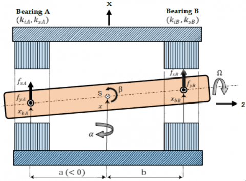
Figure 1 shows the two-dimension schematic representation of artificial heart pump, which includes a symmetrical Active Magnetic Bearing (AMB) systems at the terminals of artificial pump. Inside the airgap of motor there is a solid rotating shaft, which is called an "impeller". In this study, airgap length between the rotor and inner surface of motot is about 22 mm. The AMB system of artificial heart consists of two coils at the end of rotating shaft. The working principle of magnetic suspension for rotary impeller in the artificial heart pump is to inject controlled currents through the windings at the end of motor such that desired magnetic force is established to stabilize the rotor axial at nominal positions.
The model under consideration is an active magnetic bearing (AMB) and the Lagrange’s Equations have been used to estabilsh the dynamic behavior of impeller deviation around the center of gravity (COG) and zero Euler angles [13, 14].
Figure 1. Rigid rotor equipped with bearing magnets [14]
In Figure 1, the variables x and y represent the displacement of the rotating impeller around the center of gravity (COG). The variables α and β dedine the angular displacement of the rotor around the x and y axes, respectively. Based on Figure 1, the general motion of impeller can be described by:
$M \ddot{q}+G \dot{q}=B \cdot f$ (1)
The matrix G reflects the gyroscopic effects of forces and it includes the speed of roating shaft ω and the mass moment of inertia Iz. The diagonal matrix M contains the impeller mass m, and the moments of inertias Ix and Iy. The matrix B represnts the input matrix and the force vector is represented by f. The mass, gyroscopic, input and force matrices can be given as;
$\begin{gathered}\boldsymbol{M}=\operatorname{diag}\left[\mathrm{I}_{\mathrm{y}}, \mathrm{m}, \mathrm{I}_{\mathrm{x}}, \mathrm{m}\right], \mathbf{f}=\left[\mathrm{f}_{\mathrm{xA}}, \mathrm{f}_{\mathrm{xB}}, \mathrm{f}_{\mathrm{yA}}, \mathrm{f}_{\mathrm{yB}}\right]^{\mathrm{T}} \\ \boldsymbol{G}=\left[\begin{array}{cccc}0 & 0 & I_z \omega & 0 \\ 0 & 0 & 0 & 0 \\ -I_z \omega & 0 & 0 & 0 \\ 0 & 0 & 0 & 0\end{array}\right], B=\left[\begin{array}{cccc}a & b & 0 & 0 \\ 1 & 1 & 0 & 0 \\ 0 & 0 & a & b \\ 0 & 0 & 1 & 1\end{array}\right]\end{gathered}$
The coordinates of dynamic equations for suspended impeller are resented by the vector of variables q=[β,x,α,y]T, where, x and y are the cartesian coordinatesm while the Euler angles a and b are the deviations of impeller longitudinal axis in horizontal and verstical planes. It is worthy to notice that the impeller has to move and rotate within small aigap. The linear motion and angular positions of the rotor has not to exceed the dimensions of aigap. Any contact between the rotor and the interior surface of state is not allowable. As such the maxima of variables x_max, y_max, β_max, and α_max have not to be violated; otherwise the rotor may contact with stator internal peripheral and the damage can occur.
For further simplification, the magnetic bearing force f can be expressed in terms of rotor displacements and the coil currents [15],
$f=k_i \cdot i-k_x \cdot q_b$ (2)
where, the gain vectors ki and kx represents the force-to-current and force-to-displacement gains, respectively, and they are described by:
$\mathrm{k}_{\mathrm{i}}=\operatorname{diag}\left[\mathrm{K}_{\mathrm{iA}}, \mathrm{K}_{\mathrm{iB}}, \mathrm{K}_{\mathrm{iA}}, \mathrm{K}_{\mathrm{iB}}\right]^{\mathrm{T}}$,
$\mathrm{k}_{\mathrm{X}}=-\operatorname{diag}\left[\mathrm{K}_{\mathrm{xA}}, \mathrm{K}_{\mathrm{xB}}, \mathrm{K}_{\mathrm{XA}}, \mathrm{K}_{\mathrm{xB}}\right]^{\mathrm{T}}$,
where, the control vector of current components for the four bearing coils
$\mathrm{I}=\left[\mathrm{i}_{\mathrm{xA}}, \mathrm{i}_{\mathrm{XB}}, \mathrm{i}_{\mathrm{yA}}, \mathrm{i}_{\mathrm{yB}}\right]^{\mathrm{T}}$
The rotor displacement within the magnetic bearings qb=BTq
$\mathrm{q}_{\mathrm{b}}=\left[\mathrm{x}_{\mathrm{bA}}, \mathrm{x}_{\mathrm{bB}}, \mathrm{y}_{\mathrm{bA}}, \mathrm{y}_{\mathrm{bB}}\right]^{\mathrm{T}}$
Combining the rotor model described by Eq. (1) and the linearized bearing force model defined by Eq. (2), the following equation of motion for levitating the rigid impeller using AMBs:
$\boldsymbol{M} \ddot{q}+\boldsymbol{G} \dot{q}+\boldsymbol{B} k_x B^T q=\boldsymbol{B} k_i . i$ (3)
$\begin{gathered}\mathrm{m} \ddot{\mathrm{x}}+\left(\mathrm{k}_{\mathrm{xA}}+\mathrm{k}_{\mathrm{xB}}\right) \mathrm{x}+\left(\mathrm{a} \cdot \mathrm{k}_{\mathrm{xA}}+\mathrm{b} \cdot \mathrm{k}_{\mathrm{xB}}\right) \beta= \mathrm{k}_{\mathrm{iA}} \mathrm{i}_{\mathrm{xA}}+\mathrm{k}_{\mathrm{iB}} \mathrm{i}_{\mathrm{xB}}\end{gathered}$
$\begin{gathered}\mathrm{m} \ddot{y}+\left(\mathrm{k}_{\mathrm{xA}}+\mathrm{k}_{\mathrm{XB}}\right) \mathrm{y}+\left(\mathrm{ak}_{\mathrm{xA}}+\mathrm{bk}_{\mathrm{xB}}\right) \alpha=\mathrm{k}_{\mathrm{iA}} \mathrm{i}_{\mathrm{yA}}+\mathrm{k}_{\mathrm{iB}} \mathrm{i}_{\mathrm{yB}}\end{gathered}$
$\begin{gathered}\mathrm{I}_{\mathrm{y}} \ddot{\beta}+\mathrm{I}_{\mathrm{z}} \omega \dot{\alpha}+\left(\mathrm{a} \cdot \mathrm{k}_{\mathrm{XA}}+b \cdot \mathrm{k}_{\mathrm{xB}}\right) \cdot \mathrm{x}+\left(\mathrm{a}^2 \cdot \mathrm{k}_{\mathrm{xA}}+\right.\left.\mathrm{b}^2 \cdot \mathrm{k}_{\mathrm{xB}}\right) \cdot \beta=\mathrm{a} \cdot \mathrm{k}_{\mathrm{iA}} \cdot \mathrm{i}_{\mathrm{xA}}+b \cdot \mathrm{k}_{\mathrm{iB}} \cdot \mathrm{i}_{\mathrm{xB}}\end{gathered}$ (4)
$\begin{gathered}\mathrm{I}_{\mathrm{x}} \cdot \ddot{\alpha}-\mathrm{I}_{\mathrm{z}} \cdot \omega \cdot \dot{\beta}+\left(\mathrm{a} \cdot \mathrm{k}_{\mathrm{xA}}+\mathrm{b} \cdot \mathrm{k}_{\mathrm{xB}}\right) \cdot \mathrm{y}+\left(\mathrm{a}^2 \cdot \mathrm{k}_{\mathrm{xA}}+\right. \left.\mathrm{b}^2 \cdot \mathrm{k}_{\mathrm{xB}}\right) \cdot \alpha=\mathrm{a} \cdot \mathrm{k}_{\mathrm{iA}} \cdot \mathrm{i}_{\mathrm{yA}}+\mathrm{b} \cdot \mathrm{k}_{\mathrm{iB}} \cdot \mathrm{i}_{\mathrm{yB}}\end{gathered}$
where, the components of moment of inertia for the impeller mass are represented by Ix, Iy, and Iz. The variables a, and b denotes the distances between the AMBs (A and B) and the rotor poles or COG. Eq. (4) describes the nonlinear dynamics of AMB system for stabilizing the rigid impeller.
Based on Eq. (4) and by virtue of transformation matrix, the current control input vector U to the system can be expressed in terms vector of control signals as follows:
$\left[\begin{array}{l}\mathrm{u}_1 \\ \mathrm{u}_2 \\ \mathrm{u}_3 \\ \mathrm{u}_4\end{array}\right]=$$\left[\begin{array}{cccc}\mathrm{k}_{\mathrm{iA}} / \mathrm{m} & \mathrm{k}_{\mathrm{iB}} / \mathrm{m} & 0 & 0 \\ 0 & 0 & \mathrm{k}_{\mathrm{iA}} / \mathrm{m} & \mathrm{k}_{\mathrm{iB}} / \mathrm{m} \\ \mathrm{ak}_{\mathrm{iA}} / \mathrm{I}_{\mathrm{y}} & \mathrm{bk}_{\mathrm{iB}} / \mathrm{I}_{\mathrm{y}} & 0 & 0 \\ 0 & 0 & \mathrm{ak}_{\mathrm{iA}} / \mathrm{I}_{\mathrm{x}} & \mathrm{bk}_{\mathrm{iB}} / \mathrm{I}_{\mathrm{x}}\end{array}\right]\left[\begin{array}{c}\mathrm{i}_{\mathrm{xA}} \\ \mathrm{i}_{\mathrm{xB}} \\ \mathrm{i}_{\mathrm{yA}} \\ \mathrm{i}_{\mathrm{yB}}\end{array}\right]$
Choosing the following vectors to represent the state variables for state equation:
$\left[\begin{array}{l}\mathrm{x}_1 \\ \mathrm{x}_3 \\ \mathrm{x}_5 \\ \mathrm{x}_7\end{array}\right]=\left[\begin{array}{l}\mathrm{x} \\ \mathrm{y} \\ \beta \\ \alpha\end{array}\right],\left[\begin{array}{l}\dot{\mathrm{x}}_1 \\ \dot{\mathrm{x}}_3 \\ \dot{\mathrm{x}}_5 \\ \dot{\mathrm{x}}_7\end{array}\right]=\left[\begin{array}{l}\mathrm{x}_2 \\ \mathrm{x}_4 \\ \mathrm{x}_6 \\ \mathrm{x}_8\end{array}\right],\left[\begin{array}{l}\dot{\mathrm{x}}_2 \\ \dot{\mathrm{x}}_4 \\ \dot{\mathrm{x}}_6 \\ \dot{\mathrm{x}}_8\end{array}\right]=\left[\begin{array}{c}\ddot{\mathrm{x}} \\ \ddot{\mathrm{y}} \\ \ddot{\beta} \\ \ddot{\alpha}\end{array}\right]$ (5)
Combining Eq. (5) and Eq. (4), the dynamic equation can be written as follows:
$\dot{x}_1=x_2$
$\dot{x}_2=\mathrm{a}_1 \cdot x_5+\mathrm{a}_2 \cdot x_1+u_1$
$\dot{x}_3=x_4$
$\dot{x}_4=\mathrm{a}_1 \cdot \mathrm{x}_7+\mathrm{a}_2 \cdot \mathrm{x}_3+u_2$ (6)
$\dot{x}_5=\mathrm{x}_6$
$\dot{x}_6=\mathrm{a}_3 \cdot \mathrm{x}_8+\mathrm{a}_4 \cdot \mathrm{x}_5+\mathrm{a}_5 \cdot \mathrm{x}_1+\mathrm{u}_3$
$\dot{x}_7=\mathrm{x}_8$
$\dot{x}_8=\mathrm{a}_6 \cdot \mathrm{x}_6+\mathrm{a}_7 \cdot \mathrm{x}_7+\mathrm{a}_8 \cdot \mathrm{x}_3+\mathrm{u}_4$
where,
$a_1=-\left(\mathrm{ak}_{\mathrm{xA}}+\mathrm{bk}_{\mathrm{xB}}\right) / m, a_2=-\left(\mathrm{k}_{\mathrm{xA}}+\mathrm{k}_{\mathrm{xB}}\right) / m$,
$a_3=-\mathrm{I}_{\mathrm{z}} \omega / \mathrm{I}_{\mathrm{y}}, a_4=-\left(\mathrm{a}^2 \mathrm{k}_{\mathrm{xA}}+\mathrm{b}^2 \mathrm{k}_{\mathrm{xB}}\right) / \mathrm{I}_{\mathrm{y}}$
$a_5=-\left(\mathrm{ak}_{\mathrm{xA}}+\mathrm{bk}_{\mathrm{xB}}\right) / \mathrm{I}_{\mathrm{y}}, a_6=\mathrm{I}_{\mathrm{z}} \omega / \mathrm{I}_{\mathrm{x}}$.
$\begin{gathered}a_7=-\left(\mathrm{a}^2 \mathrm{k}_{\mathrm{xA}}+\mathrm{b}^2 \mathrm{k}_{\mathrm{xB}}\right) / \mathrm{I}_{\mathrm{x}}, a_8= -\left(\mathrm{ak}_{\mathrm{xA}}+\mathrm{bk}_{\mathrm{xB}}\right) / \mathrm{I}_{\mathrm{x}}\end{gathered}$
The PID control technique is a conventional controller, which is characterized by simplicity and easy to implement [16]. In addition, the PID controller shows good robustness and stability if it operates within linear range. The elements of PID controller consists of Proportional, Integral and Derivative gains and its transfer function is given by [17]:
$G(s)=K_p+\frac{K_i}{s}+K_d s$
where, Kp, Ki, Kd represent the proportional, integral, derivative gains, respectively. In this study, the proposed PSO method is repsonsible for tuning these gains of PID controller.
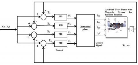
Figure 2. Stabilization of impeller for artificial heart pump based on PID controller
In Figure 2, there is a PID controller dedicated for each control channel of impeller-suspended AMB system. The control signals due to PID controller will be transformed to corresponding current actuating input of AMB system coils. There are four physical variables at the output of suspension system, which are y, α and β. These output variables are fed and compared to the reference input r to results in four corresponding errors ex, ey, eα and eβ. As indicated in Figure 2, four blocks of PID controller are required to stabilize the impler at the required nominal positions.
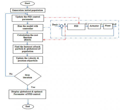
It has been shown that the setting of PID controller's gains has an impact on performance of PID-controlled system. The setting based on try-and-error procedure became old and it does not lead to optimal performance of controller. As such, this study has conducted Particle Swarm Optimization (PSO) algorithm for tuning of controller's parameters. The PSO-based tuning tries to enhance the performance of PID controller by conducting the search of algorithm to minimize the index Root Mean Square of Error (RMSE). The resultant of PSO algorithm is the optimal parameters which yields minimum RMSE. The scenario of PSO-based tuning algorithm for impeller suspension system controlled by PID controller can be visulaized in Figure 3. The figure shows the mechanism of optimization and the connection of optimizer with PID controller.
The PSO algorithm establishes the following update velocity equations to move the particles which represent the solutions of parameters towards optimal solution [18, 19]:
$\begin{gathered}V_i^{k+1}=w \cdot V_i^k+C_1 \cdot \operatorname{rand} \cdot\left(p_{\text {best }}-X_i^k\right)+C_2 . \text { rand } \cdot\left(g_{\text {best }}-X_i^k\right)\end{gathered}$ (7)
The parameters of PSO algorithm are represented by weight factors, swarm confidence factor (C2), inertia factor (w), self-confidence factor (C1). According to Eq. (7), the position update of particles (parameters) can be given by:
$X_i^{k+1}=X_i^k+V_i^{k+1}$ (8)
Based on heuristic knowledge, previous studied found that the suitable values of C1 and C2 lie within the range [1-2]. In this study, the value 2 has been chosen. The function "rand" is applied to generate random real values within the range [0,1]. The PSO algorithm has been used to find the optimal settings of PID controller's parameters. The optimization mechanism is indicated in Figure 4, where each iteration of PSO algorithm, there is an update in the parameter values of PID controller. The PSO algorithms will yield the optimal parameters at the end of iterations.
In order to evaluate errors in four channels of control, the root mean square error (RMS) is used as a cost function for this purpose. The PSO algorithm will use this cost function to update the solutions (particles) for minimum search.
$\begin{gathered}f=\sqrt{\frac{1}{n} \sum_{i=1}^n e_1(i)^2}+\sqrt{\frac{1}{n} \sum_{i=1}^n e_2(i)^2}+ \sqrt{\frac{1}{n} \sum_{i=1}^n e_3(i)^2}+\sqrt{\frac{1}{n} \sum_{i=1}^n e_4(i)^2}\end{gathered}$
where,
$\begin{gathered}e_1=x-\text { desierd, } e_2=y-\text { desired, } \\ e_3=\beta-\text { desierd, } \quad e_4=\alpha-\text { desierd }\end{gathered}$
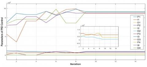
Table 1 shows the setting value that use in PSO algorithm for found the optimal value of control parameters. There are three channels of impeller suspension control. Each channel includes one PID controller and, since each PID controller consists of three terms (Kp, Kd, Ki); therefore there are 12 parameters (terms) to be tuned and optimized. The end of PSO algorithm optimal values of PID controller's parameters will be obtained which can be listed in Table 2.
Figure 3. Flowchart of the PSO algorithm
Table 1. The numeric setting of parameters for PSO
|
The Paramter of PSO Technique |
The setting value |
|
The factor of Self-cofidant $C_1$ |
2 |
|
The factor of Swarm-cofidant $C_2$ |
2 |
|
The maximum number of iteration |
15 |
|
The dimension of search space |
12 |
|
The size of Population |
20 |
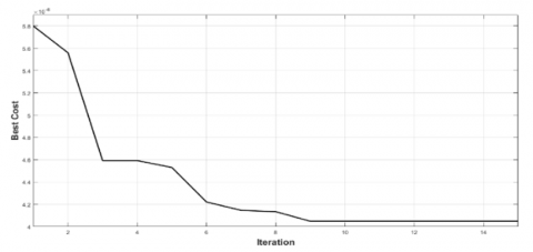
Figure 4 and Figure 5 show, respectively, the behavior of best cost and parameters of PID controller with respect to iteration evolution.
Table 2. Values of optimal PID control
|
Parameter |
Value |
Parameter |
Value |
|
$K_{p 1}$ |
73343967.544 |
$K_{p 3}$ |
53643614.633 |
|
$K_{i 1}$ |
889606950.137 |
$K_{i 3}$ |
925092538.069 |
|
$K_{d 1}$ |
362594.69 |
$K_{d 3}$ |
738680.802 |
|
$K_{p 2}$ |
77948375.897 |
$K_{p 4}$ |
26337281.855 |
|
$K_{i 2}$ |
77948375.897 |
$K_{i 4}$ |
901198115.086 |
|
$K_{d 2}$ |
104770.8155 |
$K_{d 4}$ |
551758.708 |
Figure 4. Best cost function for PSO
Figure 5. Behavior of best value for PID
This part presents the effectiveness of optimal PID controller to stabilize and perform tracking control of rotating impeller of artificial heart. The assessment of controller is evaluated via numerical simulation within the environment of MATLAB/SIMULINK programming software. The values of system parameters of artificial heart pump are listed in Table 3 [10]. The model and controller have been simulated within MATLAB-Simulink environment. The PSO algorithm has been coded within m-file. The matlab-functions have been used to develop both model and PID controller. This function can be called within Simulink library. The simulation has used variable step solver with min step size equal to 10-5 and max step size equal to 10-3. The ODE45 has been applied as numerical solver for conducting the computer simulation.
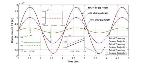
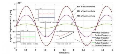
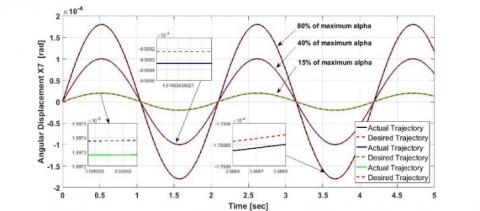
To assess the performance of PID controller for this tracking case, various tracking signals are considered. To establish platform for this evaluation, there are three levels of sinusoidal waveforms have been suggested as desired trajectory. In practical sense, the maximum levels or heights of these waveforms have not to exceed the air-gap length; otherwise, the impeller may hit the inner surface of motor. Three levels of signal excursion can be expressed in terms of percentage of air-gap deviation:
The desired signal for $15 \%$ deviation $3 \times10^{-5} \sin (4 . t)
$
The desired signal for $40 \%$ deviation $8 \times10^{-5} \sin (4 . t)
$
The desired signal for $80 \%$ deviation $1.6 \times10^{-4} \sin (4 . t)
$
Table 3. Parameter value of artificial heart pump [14]
|
Value |
Description of AMB's Parameters |
|
0.2 mm |
The length of Air-gap $\ell_{\text {air }}$ |
|
-10000 N/m |
Bearing stiffness ($K_{x A}=K_{x B}$) |
|
6.32 ×10⁻⁷Kg.m2 |
The moment of inertia around x and y axes ($I_x=I_y$) |
|
2×10⁻⁸Kg.m2 |
The moment of inertia around z-axis ($I_z$) |
|
0.01 m |
The distance from ABM2 to COG (b) |
|
- 0.01 m |
The distance from ABM1 to COG (a) |
|
100 N/A |
The bearing stiffness of current ($K_{i A}=K_{i B}$ ) |
|
10000 rpm |
The angular velocity of impeller ($\Omega$) |
|
0.0182 rad |
Maximum deviation in angular position ($\beta_{\max }=\alpha_{\max }$) |
|
12.42×10⁻³ kg |
The Mass of rotating shaft ($M$) |
For this tracking case, the dynamic behaviors of linear and angular displacements are shown in Figure 6 under above desired trajectories. Based on the figure, it is evident that the optimized PID controllers could successfully enable the state variables $x, y, \beta$ and $\alpha$ of rotating shaft (impeller) to coincide with the desired trajectories within the small air-gap.
a. Behavior of displacement x
b. Behavior of displacement $y$
c. Behavior of displacement $\beta$
d. Behavior of displacement $\alpha$
Figure 6. The responses of state variables $x, y, \beta$ and $\alpha$ subjected to different desired trajectories
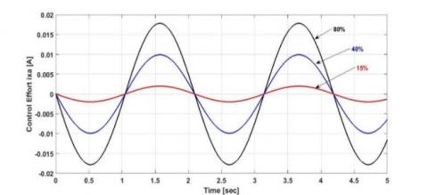
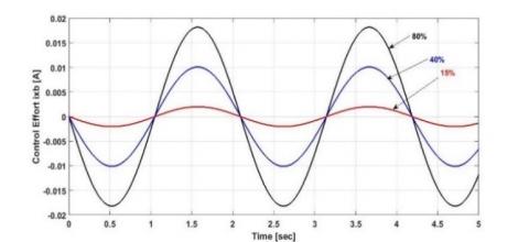
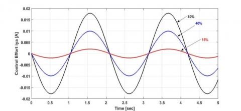
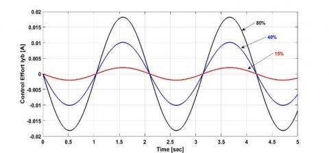
In Figure 7, the behaviors of control currents flowing through the coils of AMB system are illustrated. According to the figure, the larger deviation of impeller displacements (linear and angular displacements) subjected sinusoidal desired trajectories results in higher actuating control signals ($i_{x a}, i_{x b}, i_{y a}, i_{y b}$). Of course, these higher actuating currents require higher flux intensity to enable the state variables of pump impeller to follow the desired positions as indicated in Figure 7.
a. The behavior of control current $i_{x a}$
b. The behavior of control current $i_{x b}$
c. The behavior of control current $i_{y a}$
d. The behavior of control current $i_{y b}$
Figure 7. Control efforts of tracking control
Table 4 shows the evaluation of linear and angular displacements ($x, y, \beta, \alpha$) at initial conditions described by percentages (80%, 40%, 15%) with respect to air-gap length. The assessment has been determined by Root Mean Square (RMS) of variable behaviors. Table 5 reports the intensities of currents flowing through the bearing windings at the aforementioned percentages. These currents are responsible for returning the impeller at nominal positions. Again, the currents have evaluated in terms of their RMS.
Table 4. RMS of variable behaviors at different initial conditions
|
|
$\mathrm{X}(\mathrm{m})$ |
$\mathrm{Y}(\mathrm{m})$ |
$\beta(\mathrm{rad})$ |
$\alpha(\mathrm{rad})$ |
|
80% |
1.153×10⁻⁴ |
1.153×10⁻⁴ |
1.154×10⁻⁴ |
1.153×10⁻⁴ |
|
40% |
5.773×10⁻⁵ |
5.772×10⁻⁵ |
5.781×10⁻⁵ |
5.772×10⁻⁵ |
|
15% |
2.163×10⁻⁵ |
2.162×10⁻⁵ |
2.165×10⁻⁵ |
2.162×10⁻⁵ |
Table 5. RMS of winding currents at different initial conditions
|
|
Ixa (A) |
Ixb (A) |
Iya (A) |
Iyb (A) |
|
80% |
0.0114 |
0.0117 |
0.0114 |
0.0117 |
|
40% |
0.0057 |
0.0058 |
0.0057 |
0.0058 |
|
15% |
0.0021 |
0.0022 |
0.0021 |
0.0022 |
In this study, the design of PID controller has been presented to perform tracking control of pump rotary shaft (impeller) for axial artificial heart. There are four control channels which apply four PID controllers for magnetic suspension and tracking. The PSO algorithm has been utilized to enhance the tracking performance of conventional PID controller by optimal tuning of their terms (Kp, Kd and Ki). Based on numerical simulation, the PSO algorithm shows good search towards minimum solutions. Moreover, the optimal PID controller shows good tracking performance when subjected to desired trajectories of sinusoidal waveforms with different heights.
Future extension of this study, one cannn suggest other control strategies to suspend the motion of heart impeller and a comparison study can be conducted between the proposed controller and these suggested controllers [20-30].
[1] Iaizzo, P.A. (2010). Handbook of cardiac anatomy, physiology, and devices. Springer Science & Business Media.
[2] Peter, L.F. (1990). Artificial Heart. 3 Springer Tokyo.
[3] Yamane, T. (2016). Mechanism of Artificial Heart. Japan: Springer.
[4] Hoshi, H., Shinshi, T., Takatani, S. (2006). Third-generation blood pumps with mechanical noncontact magnetic bearings. Artificial Organs, 30(5): 324-338. https://doi.org/10.1111/j.1525-1594.2006.00222.x
[5] Yang, Z.X., Zhao, G.S., Rong, H.J., Yang, J. (2016). Adaptive backstepping control for magnetic bearing system via feedforward networks with random hidden nodes. Neurocomputing, 174: 109-120. https://doi.org/10.1016/j.neucom.2014.12.116
[6] Yang, S.M., in, C.C. (2007). Performance of a single-axis controlled magnetic bearing for axial blood pump. 2007 IEEE Industry Applications Annual Meeting, New Orleans, LA, USA, 2007, pp. 963-968. https://doi.org/10.1109/07IAS.2007.149
[7] Humaidi, A.J., Kadhim, S.K., Gataa, A.S. (2022). Optimal adaptive magnetic suspension control of rotary impeller for artificial heart pump. Cybernetics and Systems, 53(1): 141-167. https://doi.org/10.1080/01969722.2021.2008686
[8] Chen, H.C. (2008). Optimal fuzzy PID controller design of an active magnetic bearing system based on adaptive genetic algorithms. In 2008 International Conference on Machine Learning and Cybernetics, Kunming, China, pp. 2054-2060. https://doi.org/10.1109/ICMLC.2008.4620744
[9] Humaidi, A.J., Kadhim, S.K., Gataa, A.S. (2020). Development of a novel optimal backstepping control algorithm of magnetic impeller-bearing system for artificial heart ventricle pump. Cybernetics and Systems, 51(4): 521-541. https://doi.org/10.1080/01969722.2020.1758467
[10] Humaidi, A.J., Badr, H.M. (2018). Linear and nonlinear active disturbance rejection controllers for single-link flexible joint robot manipulator based on PSO tuner. Journal of Engineering Science & Technology Review, 11(3): 133-138. https://doi.org/10.25103/jestr.113.18
[11] Hassan, R.F., Ajel, A.R., Abbas, S.J., Humaidi, A.J. (2022). FPGA based HIL co-simulation of 2DOF-PID controller tuned by PSO optimization algorithm. ICIC Express Letters, 16(12): 1269-1278. https://doi.org/10.24507/icicel.16.12.1269
[12] Humaidi, A., Hameed, M. (2019). Development of a new adaptive backstepping control design for a non-strict and under-actuated system based on a PSO tuner. Information, 10(2): 38. https://doi.org/10.3390/info10020038
[13] Maslen, E.H., Schweitzer, G. (2009). Magnetic Bearings: Theory, Design, and Application to Rotating Machinery. Berlin, Heidelberg: Springer-Verlag Berlin Heidelberg. https://doi.org/10.1007/978-3-642-00497-1
[14] Bogdanova, Y.V., Guskov, A.M. (2016). Synergetic control of magnetic bearings in artificial heart ventricle rotor. Biomedical Engineering, 50(3): 152-156. https://doi.org/10.1007/s10527-016-9608-0
[15] Polajzer, B. (2010). Magnetic Bearings, Theory and Applications. https://doi.org/10.5772/245
[16] Humaidi, A.J., Abdulkareem, A.I. (2019). Design of augmented nonlinear PD controller of Delta/Par4-like robot. Journal of Control Science and Engineering, 2019: 7689673. https://doi.org/10.1155/2019/7689673
[17] Al-Jodah, A., Abbas, S.J., Hasan, A.F., Humaidi, A.J. Al-Obaidi, A.S.M., AL-Qassar, A.A., and Hassan, R.F. (2023). PSO-based optimized neural network PID control approach for a four wheeled omnidirectional mobile robot. International Review of Applied Sciences and Engineering 14 (1): 58–67. https://doi.org/10.1556/1848.2022.00420
[18] Humaidi, A.J., Oglah, A.A., Abbas, S.J., Ibraheem, I.K. (2019). Optimal augmented linear and nonlinear PD control design for parallel robot based on PSO tuner. International Review on Modelling and Simulations, 12(5): 281-291. https://doi.org/10.15866/iremos.v12i5.16298
[19] Humaidi, A.J., Badr, H.M., Hameed, A.H. (2018). PSO-based active disturbance rejection control for position control of magnetic levitation system. In 2018 5th International Conference on Control, Decision and Information Technologies (CoDIT), Thessaloniki, Greece, pp. 922-928. https://doi.org/10.1109/CoDIT.2018.8394955
[20] Humaidi, A.J., Hameed, M.R., Hameed, A.H. (2018). Design of block-backstepping controller to ball and arc system based on zero dynamic theory. Journal of Engineering Science and Technology, 13(7): 2084-2105.
[21] Hassan, M.Y., Humaidi, A.J., Hamza, M.K. (2020). On the design of backstepping controller for Acrobot system based on adaptive observer. International Review of Electrical Engineering (IREE), 15(4): 328-335.
[22] Abdul-Kareem, A.I., Hasan, A.F., Al-Qassar, A.A., Humaidi, A.J., Hassan, R.F., Ibraheem, I.K., Azar, A.T. (2022). Rejection of wing-rock motion in delta wing aircrafts based on optimal LADRC schemes with butterfly optimization algorithm. Journal of Engineering Science and Technology, 17(4): 2476-2495.
[23] Husain, S.S., Kadhim, M.Q., Al-Obaidi, A.S.M., Hasan, A.F., Humaidi, A.J., Al-Husaeni, D.N. (2023). Design of robust control for vehicle steer-by-wire system. Indonesian Journal of Science & Technology, 8 (2): 197-216. https://doi.org/10.17509/ijost.v8i2.54794
[24] Humaidi, A.J., Hameed, M.R. (2017). Design and performance investigation of block-backstepping algorithms for ball and arc system. In 2017 IEEE International Conference on Power, Control, Signals and Instrumentation Engineering (ICPCSI), Chennai, India, pp. 325-332. https://doi.org/10.1109/ICPCSI.2017.8392309
[25] Mahdi, S.M., Yousif, N.Q., Oglah, A.A., Sadiq, M.E., Humaidi, A.J., Azar, A.T. (2022). Adaptive Synergetic Motion Control for Wearable Knee-Assistive System: A Rehabilitation of Disabled Patients. Actuators, 11: 176. https://doi.org/10.3390/act11070176
[26] Humaidi, A.J., Hameed, A.H. (2017). Robustness enhancement of MRAC using modification techniques for speed control of three phase induction motor. Journal of Electrical Systems, 13(4): 723-741.
[27] Al-Khazraji, H., Nasser, A.R., Hasan, A.M., Al Mhdawi, A.K., Al-Raweshidy, H., Humaidi, A.J. (2022). Aircraft engines remaining useful life prediction based on a hybrid model of autoencoder and deep belief network. IEEE Access, 10: 82156-82163. https://doi.org/10.1109/ACCESS.2022.3188681
[28] Humaidi, A.J., Hussein, H.A. (2019). Adaptive control of parallel manipulator in cartesian space. In 2019 IEEE International Conference on Electrical, Computer and Communication Technologies (ICECCT), Coimbatore, India, pp. 1-8. https://doi.org/10.1109/ICECCT.2019.8869257
[29] Humaidi, A.J., Hameed, A.H., Hameed, M.R. (2017). Robust adaptive speed control for DC motor using novel weighted E-modified MRAC. In 2017 IEEE International Conference on Power, Control, Signals and Instrumentation Engineering (ICPCSI), Chennai, India, pp. 313-319. https://doi.org/10.1109/ICPCSI.2017.8392302
[30] Humaidi, A.J., Tala'at, E.N., Hameed, M.R., Hameed, A.H. (2019). Design of adaptive observer-based backstepping control of cart-pole pendulum system. In 2019 IEEE International Conference on Electrical, Computer and Communication Technologies, pp. 1-5. IEEE.