Sonia Hamdouche* | Said Drid![]()
© 2023 IIETA. This article is published by IIETA and is licensed under the CC BY 4.0 license (http://creativecommons.org/licenses/by/4.0/).
OPEN ACCESS
The induction machine (IM) is a nonlinear, multivariable, strongly coupled system. Therefore, it is necessary to achieve a decoupling between flux and torque. The vector control technique is the one that gives better performance. To have high dynamic responses and better torque control, the machine must be supplied with sinusoidal currents. The present work contributes to improving the efficiency of a flux-oriented indirect control (IFOC) of an induction motor associated with a new hysteresis inverter. The Induction motors have good efficiencies when operating at full load. However, at lower than rated loads, which is a condition that many machines experience for significant portion of their service life, the efficiency is greatly reduced. To improve the efficiency of the existing motor it is important to regulate the flux of the motor in the desired operating range. This paper proposes the analytical approach of minimizing copper losses for an induction motor and energy efficient control strategy based on fuzzy logic using Matlab / Simulink®. This parameter is used to determine an optimal rotor flux reference it has the goal of maximizing the efficiency for each given load torque. The proposed fuzzy controller adjusts the electromagnetic torque, to give the optimized flux by minimizing losses.
loss minimization, efficiency machine, optimal rotor flux, hysteresis inverter
Currently, the research scientific around the world are engaged for the environment and energy conservation. The interest in the various problems posed firstly, push states to remodel their Energy and Environmental strategies, and secondly to put the inventors and the manufacturers of electrical systems in front of an important challenge which is clean energy.
The electrical energy is placed in the category of clean energy during its use but sometimes it's not suitable during its production. Moreover, energy demand and the cost of its production and its operation are constantly increasing. This leads us to improving the efficiency of systems producing or consuming electrical energy [1].
Improving the efficiency of this large energy consumer will necessarily lead to significant savings in energy and money. Opting for an electric vehicle, it means choose an ecological automobile and less polluting in the use and also more silent to contribute for reducing disturbance noise… and improve our health grace to the absence of CO2 emissions.
Nowadays, a serious problem is mentioned by the industry, namely the high energy consumption in the face of increasingly limited energy sources. Several strategies and measures have been suggested to remedy this consumption which is growing [1].
Among these solutions, we can cite the reduction of electric energy consumption starting from the engines which generally constitute a large part of the high energy consumption equipment in the industry.
In the context of electric traction, the energy efficiency of the entire traction chain is essential. Indeed, asynchronous motors (our choice of study) that are included in this chain of traction have a good performance at the nominal point which degrades quickly outside this point of operation.
The efficiency of the induction motor can be improved by an optimal control of flux allowing the minimization of the machine losses. The induction motor losses can be classified into four types: Electrical losses, Magnetic losses, Mechanical losses, and supplementary losses. The effort is carried on the reduction of Electrical losses because they represent between 55% and 60% total losses of the machine and they are controllable. Many studies have identified several possible methods of minimizing machine losses [2, 3].
Several studies have participated improving the efficiency of asynchronous machines based on flux regulation because asynchronous motors operate at nominal flux even at low load by varying the load torque. Drid et al. [2] told about how to maximize engine efficiency for each value of load torque by genetic algorithm.
A loss model-based energy efficient control strategy for the IM using an optimal rotor flux reference has been accomplished by [3] which is determined using two advanced particle swarm optimization (PSO) algorithms, known as the dynamic particle swarm optimization (Dynamic PSO) and the chaos particle swarm optimization (Chaos PSO) algorithms.
The control schemes used in industry operate at constant flux at its nominal value. In this case, the engine operates at rated speed [4, 5], the increased losses lead to excessive consumption of electrical energy, due to the reduced load [6, 7].
Adjusting the flux level of the motor using the IM loss model taking into account the variation of the parameters of the induction machine [8, 9], a genetic algorithm [10, 11] and a particle swarm [12] allowed the determination of the optimum flux level for efficient energy control using IM. Loss model.
If a losses model of the induction motor is available [13-15], the optimal flux by minimizing the losses can be calculated analytically. Although this method is characterized by its simplicity, the engine information must be known precisely.
The efficiency of the machine can be optimized, by finding the optimal values of the voltage and frequency of the drives based on the minimization of the induction motor losses. Many researches algorithms have been used. For induction motor efficiency optimization include Genetic Algorithm [8, 9], PSO, used to find the optimum values of the excitation voltage and frequency [10].
Improving efficiency by optimizing the waveforms provided by the inverter. Several strategies have been reported in the literature to reduce MI losses. Some algorithms use current [11], voltage [9], rotor flux [12] and other parameters.
At this point, we have studied the inverter machine association, where we use two types of inverter control, PWM and a new technique rectified currents hysteresis. However, this technique offers lower switching frequencies compared to PWM, giving us a non-rippled efficiency.
The induction machine (IM) is a nonlinear, multivariable, strongly coupled system. Therefore, it is necessary to achieve a decoupling between flux and torque. The vector control technique is the one that gives better performance. To have high dynamic responses and better torque control, the machine must be supplied with sinusoidal currents. However, some of these techniques deliver high switching frequencies and hysteresis band overshoots, and others have the disadvantage of phase current drift with respect to its reference [16-19].
In this work, we present a new hysteresis technique that provides a significant reduction in switching frequency and hysteresis band overshoots as well as the elimination of phase current drift from their references.
Also we will propose a strategy Minimizing copper loss of the asynchronous machine by generating the optimal flux Based on fuzzy logic.
This paper is organized into five sections. The mathematical model of IM and the principal of the inverter control with rectified currents hysteresis are introduced in section 2. In section 3, Analytical development of the optimal flux that ensures minimal losses is presented. Section 4 concerns flux optimization based on fuzzy logic. Finally, section 5 the simulation results are exposed and comparative illustration shows the performance of efficiency with flux optimization.
The vector control of the induction motor was invented by professor HASSE and professor BLASCHKE form university of Brunswick in 1968 [16, 17]. The main idea is to have the induction motor behavior be similar to that of a DC motor. Because it is well known that the induction motor model is nolinear and strongly coupled (Flux-torque) unlike to the DC motor.
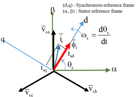
The vector control consists to keep the vector components of rotor flux as given in equation (1) and as illustrated on Figure 1 [18].
$\left\{\begin{array}{l}\phi_{r d}=\phi_r \\ \phi_{r q}=0\end{array}\right.$ (1)
Figure 1. Rotor flux orientation principle
The computation of the orientation angle is done the equations given by (2) [18].
$\left\{\begin{array}{l}\omega_{s l}=\frac{M}{T_r \phi_r} I_{s q} \\ \omega_s=\omega_{s l}+p . \Omega \\ \theta_s=\int \omega_s d t\end{array}\right.$ (2)
As a result of this orientation the flux and the torque will be decoupled equation (3) [18].
$\left\{\begin{array}{l}\phi_r=\frac{M}{T_r \mathbf{s}+1} I_{s d} \\ C_e=p \frac{M}{L_r} \phi_r I_{s q}\end{array}\right.$ (3)
We notice the rotor flux depends on the direct component of the stator current and the torque depends on quadratic component.
Stator, flux and speed control:
The dynamics of stator currents rotor flux and mechanical speed are represented by (3), (4) and (6) respectively. Than the control of theses state variables is essay by using the placement poles technique [16-18].
$\left\{\begin{array}{l}I_{s d}=\frac{1}{\sigma L_s \mathbf{s}+R_s}\left(V_{s d}-e_d\right) \\ I_{s q}=\frac{1}{\sigma L_s \mathbf{s}+R_s}\left(V_{s q}-e_q\right)\end{array}\right.$ (4)
where electrical coupling terms are given as follows:
$\left\{\begin{array}{l}e_d=\frac{M}{L_r} \frac{d \phi_r}{d t}-\sigma L_s \omega_s I_{s q} \\ e_q=\phi_r \omega_s I_{s q}+\sigma L_s \omega_s I_{s q}\end{array}\right.$ (5)
The mechanical equation is:
$\Omega=\frac{1}{J \mathbf{s}+f}\left(C_e-C_r\right)$ (6)
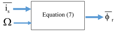
The flux orientation vector control requires knowledge of the rotor module of the rotor flux. To do this, we can estimate the flux using the rotor equation (7) expressed in the stator reference frame, as shown on Figure 2 [18].
$\left\{\begin{array}{l}0=-\frac{M}{T_r} I_{s \alpha}+\frac{1}{T_r} \phi_{r_\alpha}+\frac{d \phi_{r \alpha}}{d t}+p \cdot \Omega \cdot \phi_{r \beta} \\ 0=-\frac{M}{T_r} I_{s \beta}+\frac{1}{T_r} \phi_{r_\alpha}+\frac{d \phi_{s \beta}}{d t}-p . \Omega \cdot \phi_{r \alpha} \\ \phi_r=\sqrt{\phi_{r \alpha}^2+\phi_{r \beta}^2}\end{array}\right.$ (7)
Figure 2. Rotor flux estimation
Sinusoidal PWM strategy
The SPWM is the widely strategy used to control the inverter. It consists to compart the reference voltage (low frequency) with the triangular carrier signal (high-frequency), Figure 3.
Figure 3. SPWM
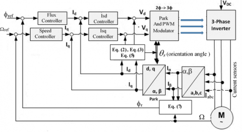
Figure 4. Vector control Block diagram of the induction motor using SPWM
Figure 4 presents the general diagram of the oriented vector for the induction motor. Also the Speed, Rotor flux, stator current control loops and the flux orientation blocks are presented.
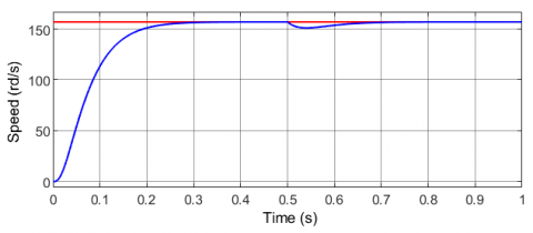
To test the vector control, some simulations have been done to control the speed at 157rd/s. After stating the motor without load, a torque load 20Nm is applied at 0.5s. The flux rotor is maintained to 1web.
Simulation and results
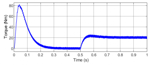
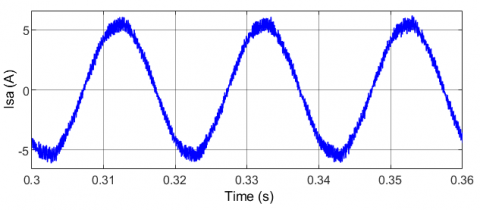
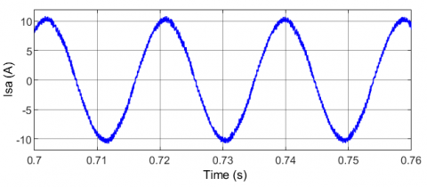
The results show the performance of the vector control to tracking speed and flux to their references in transient state as well as in steady state, Figures 5 and 6. The paramertes of IM are giveen in the appendix, Table 5. However, we notice the torque presents same oscillations due to the switching frequency, Figure 7. Also there is a distortion the current stator, Figures 8, 9, 10.
Figure 5. Speed response versus time
Figure 6. Rotor flux response versus time
Figure 7. Torque response versus time
Figure 8. Phase (A) stator current response versus time
Figure 9. Zoom of Phase (A) stator current (unloaded motor)
Figure 10. Zoom of Phase (A) stator current (Loaded motor 20Nm)
Our objective is to have torque reponse and currents not rippled, which gives us a good efficiency of the machine, the method used is to replace the PWM with rectified hysteresis regulators, this method has given us a great improvement in the levels currents, torque and speed.
This technique is derived from the principle hysteresis control, where the currents of the three phases of the machine are rectified before being controlled by the hysteresis comparator, allows operation at low switching frequency.
The principle of this method consists to define in the stator reference plan (a, b), eight voltage vectors Ui (i=0-7) corresponding to the possible positions of the inverter switches, these vectors define in their turn six sectors, Figure 11.
Figure 11. Illustration of rectified stator current
In the middle of each sector we create a new variable reference plan ai bi (i=1, 6). For example, according to the reference voltage position, when the stator current error vector (Di=ire-i) is located in sector 2, the referential (a2 b2) is considered the current error vector is therefore decomposed into two components Diai and Dib serving as input signals of the hysteresis controllers. The output signals (ha and hb) determine the switches state [19].
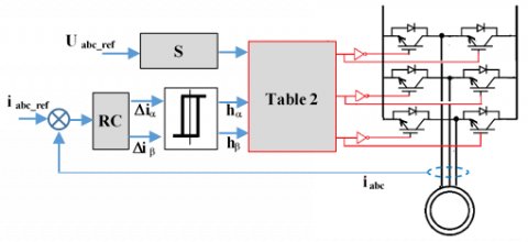
The synoptic diagram of this technique is mentioned in the Figure 12.
Figure 12. Block diagram of the control system by rectified currents
• From the information on the voltages control, the block "S" performs the identification of the sector by detecting the zero crossing of the stator voltages and giving the.
• Binary vector V whose expression is the following [19]:
$V=\left[\begin{array}{ll}V & 1 \\ V & 2 \\ V & 3\end{array}\right]=\frac{1}{2}\left[\begin{array}{c}1+\operatorname{sgn}\left(U_{12 r e f}\right) \\ 1+\operatorname{sgn}\left(U_{23 r e f}\right) \\ 1+\operatorname{sgn}\left(U_{12 \text { ref }}-U_{23 r e f}\right)\end{array}\right]$ (8)
• The rectified current error vectors Dira and Dirb are obtained from Information available at the input of the "RC" block which is V and DI as shown in Figure 2 The vectors Dira and Dirb are defined by the following expressions and mentioned in Table 1 [19]:
$\left\{\begin{array}{l}\Delta i_{r \alpha}=\bar{r}_\alpha^T \bar{i}_\alpha \\ \Delta i_{r \beta}=\bar{r}_\beta^T \bar{i}_\beta\end{array}\right.$ (9)
With
$\begin{gathered}\bar{i}_\alpha=\left[\begin{array}{ll}i_1 & i_2\end{array}\right]^T ; \bar{i}_\beta=\frac{1}{\sqrt{3}}\left[\begin{array}{cc}i_1 & -i_2 \\ i_2 & -i_3\end{array}\right] ; \\ \bar{r}_\alpha=\left[\begin{array}{ccc}0 & 1 & -1 \\ 1 & 0 & -1\end{array}\right] \bar{V} ; \bar{r}_\beta=\left[\begin{array}{ccc}1 & 0 & -1 \\ 0 & 1 & -1\end{array}\right] \bar{V}\end{gathered}$
Table 1. Definition the control variables
|
Sector N° |
V1 |
V2 |
V3 |
$\Delta \mathrm{i}_{\mathrm{i} \alpha}$ |
$\Delta \mathrm{i}_{i \beta}$ |
|
1 |
1 |
1 |
0 |
$(\mathrm{i} 1-\mathrm{i} 3) / \sqrt{3}$ |
-i2 |
|
2 |
0 |
1 |
0 |
$(\mathrm{i} 2-\mathrm{i} 3) / \sqrt{3}$ |
i1 |
|
3 |
0 |
1 |
1 |
$(\mathrm{i} 2-\mathrm{i} 1) / \sqrt{3}$ |
-i3 |
|
4 |
0 |
0 |
1 |
$(\mathrm{i} 3-\mathrm{i} 1) / \sqrt{3}$ |
i2 |
|
5 |
1 |
0 |
1 |
$(\mathrm{i} 3-\mathrm{i} 3) / \sqrt{3}$ |
-i1 |
|
6 |
1 |
0 |
0 |
$(\mathrm{i} 1-\mathrm{i} 2) / \sqrt{3}$ |
i3 |
• The vectors $\Delta \mathrm{i}_{\mathrm{r} \alpha}$ and $\Delta \mathrm{i}_{\mathrm{r} \beta}$ are the input variables of two hysteresis comparators. At the output of these comparators two bands are delivered $h_\alpha$ along axis $\alpha$ and $h_\alpha$ along $\operatorname{axis} \beta$.
• The switching states of the inverter switches Sa, Sb and Sc are obtained from Table 2 as a function of the values V, $\mathrm{h}_\alpha$ and $\mathrm{h}_\beta$ [19].
The switching sequences (Table2) Ui (i=0-7), depend on ($\mathrm{h}_\alpha$, $\mathrm{h}_\beta$) the output of hysteresis controllers of $\Delta i_{i \alpha}$ and $\Delta i_{i \beta}$.
Table 2. Switching sequences
|
|
($h \alpha$, $\boldsymbol{h} \boldsymbol{\beta}$) |
|||
|
Sector N° |
00 |
01 |
10 |
11 |
|
1 |
U7 |
U0 |
U2 |
U1 |
|
2 |
U0 |
U7 |
U3 |
U2 |
|
3 |
U7 |
U0 |
U4 |
U3 |
|
4 |
U0 |
U7 |
U5 |
U4 |
|
5 |
U7 |
U0 |
U6 |
U5 |
|
6 |
U0 |
U7 |
U1 |
U6 |
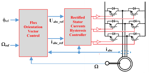
Figure 13. Vector control Block diagram of the induction motor using RSCHC
The simulations of the Vector control using RSCHC (Figure 13) is done with the same condition as with SPWM.
Simulation and results
The results are organized as follow:
Figure 14. Speed response versus time
Figure 15. Rotor flux response versus time
Figure 16. Torque response versus time
Figure 17. Phase (A) stator current response versus time
Figure 18. Zoom of Phase (A) stator current (unloaded motor)
Figure 19. Zoom of Phase (A) stator current (Loaded motor 20Nm)
The results show the performance of the vector control to tracking speed and flux to their references in dynamics as well as in steady state, Figures 14 and 15. However, we notice that the torque oscillations (Figure 16) are reduced compared with Figure 7. Also we can obseve that the stator current is sinsoidal, Figures 17, 18, 19.
With SPWM the switching frequency is fixed thus and the distribution of the harmonics cannot be changed, in order to allow efficient operation of the motor operating at variable speed.
We have chosen a simplified loss model which takes account only the copper losses. The joule losses of the induction motor are divided into two: the stator joule losses and the rotor joule losses. So the sum of the two losses gives us [20-24]:
$P_j=R_s\left(I_{s d}^2+I_{s q}^2\right)+R_r\left(I_{r d}^2+I_{r q}^2\right)$ (10)
In the steady state, the first equation of (3) can be written:
$I_{s d}=\frac{\phi}{M}$ (11)
Due to its no accessibility, the rotor current is expressed as a function of the stator current as follows:
$\left\{\begin{array}{c}I_{r d}=\frac{\phi_r}{L_r}-\frac{M}{L_r} I_{s d} \\ I_{r d}=-\frac{M}{L_r} I_{s q}\end{array}\right.$ (12)
The second equation of (3) can be written:
$I_{s q}=\frac{C_e}{p \frac{M}{L_r} \phi_r}$ (13)
By remplacing (11), (12) and (13) in (10), we obtain:
$P_j=K_1 \phi_r^2+K_2 \frac{C_e^2}{\phi_r^2}$ (14)
where, $K_1=\frac{R_s}{M^2}$ and $K_2=\frac{R_s L_r^2}{p^2 M^2}+\frac{R_r}{p^2}$.
We obtain a loss equation as a function of the IM parameters, the electromagnetic torque and the rotor flux. The resolution of equation (14) allows us to obtain the optimum flux which ensures minimum losses. To solve this equation, derivative action equation (15), it is also called the sensitivity of the input power [20-24]:
$\frac{d P_j}{d \phi_r}=2 K_1 \phi_r-2 \phi_r K_2 \frac{C_e^2}{\phi_r^4}$ (15)
Finally, the minimization of stator and rotor losses is obtained from the optimized rotor flux $\phi r_{-} o p t$:
$\phi_{r_{-} \_o p t}=\left(\frac{K_2}{K_1}\right) \sqrt[1 / 4]{C_e}$ (16)
Most complex industrial systems are difficult to control automatically. These problems are due to nonlinearity and to the variation of the parameters of these systems as well as the quality of the measurable variables. In order to provide a solution to these problems, a new control strategy based on "Fuzzy logic theory" has been developed the origin of the development of this theory was process control based on the expertise of the operator [19, 20]. In a control loop, human reacts like nonlinear robust controller whose parameters vary during the time. This control strategy «Human" needs to know process to order fuzzy controllers can be seen as a case of expert control characterized by the use of a mechanism representing the judgment of the human being [19, 24].
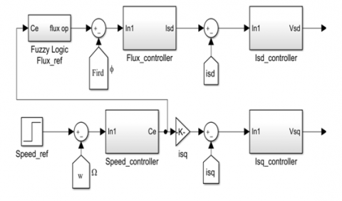
The proposed diagram Figure 20, explains the input and output variables used for optimization system.
The input variables are the torque component Ce and its variation ΔC, the output is the Flux component φopt which has the goal of minimizing the copper losses [23, 24]. The Control rules are summarized in Table 3.
Table 3. Fuzzy rules
|
|
Ce |
NH |
NM |
NS |
ZE |
PS |
PM |
PH |
|
∆Ce |
|
|||||||
|
N |
N |
N |
NS |
ZE |
PS |
PS |
P |
|
|
ZE |
N |
N |
NS |
ZE |
PS |
P |
P |
|
|
P |
N |
NS |
NS |
ZE |
PS |
P |
P |
|
Figure 20. Membership functions for proposed scheme
As well as the simulation block diagram of this technique which is shown by the Figure 21:
Figure 21. Flux optimization scheme
Figure 22. Block diagram of proposed control scheme
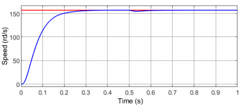
To test the efficiency of the proposed scheme (Figures 21, 22), simulations have been done to control the speed at 157rd/s.
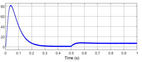
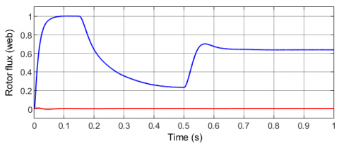
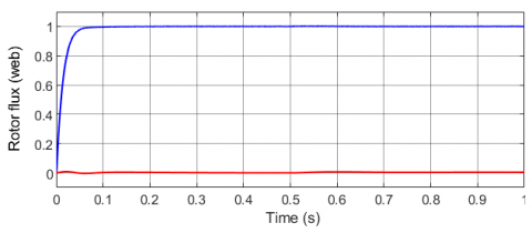
The induction motor is started with 1Nm, after thad a torque load is changed to 7Nm at 0.5s (see Figure 23). The flux is generated by a fuzzy optimiser according the torque laod in order to reduce the losses. The results are compared to the thoses were the flux is maintained to 1web, Figures 24, 25, 26 27, 28, 29, 30 and 31.
Figure 23. Torque profile
Figure 24. Speed response versus time
Figure 25. Torque response versus time
Figure 26. Rotor flux response versus time
Figure 27. Rotor flux response versus time
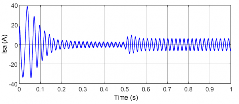
Figure 28. Phase a stator current response versus time
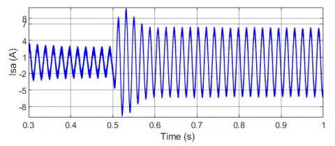
Figure 29. Phase (A) stator current response versus time
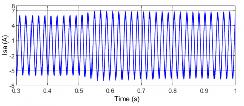
Figure 30. Zoom of Phase (A) stator current (without optimization)
Figure 31. Zoom of Phase (A) stator current (with optimization)
The simulation which gives an optimized efficiency based on the fuzzy logic is performed using Matlab/Simulink®; the parameters of the machine used are given in appendix Table 5. And the results of the simulation are given in figures below.
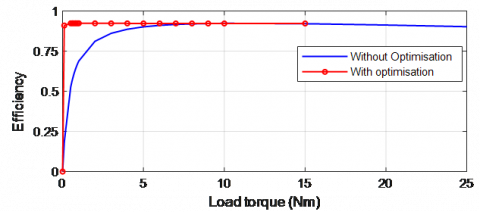
We start with the evaluation of the efficiency as a function of the load torque for different loads Figure 32 clearly shows the performance efficiency with flux optimization based on fuzzy logic compared to the efficiency without optimization.
Figure 32. Efficiencies for several Loads
The results of Table 4 show us that the efficiency of the machine increases up to 0.9233 for the system with optimization but in the system without optimization it stops at 0.8923. This observation allows us to say that the flux optimization of the machine based on fuzzy logic gave us a good improved efficiency.
Table 4. Efficiency values with optimization and without optimization
|
Load |
Without Optimization |
With Optimization |
|
0 |
0 |
0 |
|
0.5 |
0.5272 |
0.9237 |
|
0.9 |
0.6663 |
0.9242 |
|
1 |
0.6889 |
0.9242 |
|
5 |
0.9018 |
0.9233 |
|
20 |
0.9029 |
0.9029 |
|
30 |
0.8923 |
0.8923 |
The results clearly show the contribution of the optimized control in the copper losses, the stator currents of the machine evolve around their reference with a much slower dynamic.
The SPWM technique has a high and fixed switching frequency, which is not the case with the technique with hysteresis of the rectified currents. In the proposed technique the switching frequency inverter is optimized and lower than the SPWM. The advantages are a reduction of the electromagnetic torque ripples, reduction of the inverter switching losses and the stator current with optimization with low distortions.
In this paper, a rotor flux oriented vector control of the induction motor is presented. The motor is supplied through two level inverter using a new technique of rectified hysteresis current control. This technique is based on the hysteresis control principle, where the currents of the three phases of the machine are rectified before being controlled by the hysteresis comparator, allows a low switching frequency operation.
Also, an analytical approach is exposed to minimizing the copper losses of the induction motor. This approach has been addressed and applied to improve the effectiveness of induction motor using a fuzzy logic. The strategy adopted consists to adjust the rotor flux according the value of the load torque to reduce the stator current, thus the optimizing Efficiency.
The results show the utility of efficiency optimization used fuzzy logic, when the machine is associated with rectified currents hysteresis control and confirm largely the effectiveness of the proposed control scheme.
Future research will be oriented towards the implementation of the proposed control on an electric vehicle.
Table 5. Parameters of induction motor
|
Rate values |
|
|
Power Torque Speed Current Voltage |
P=4 kW Cn=25Nm Nn=1440 rpm In= 15∕8.6A Vs=220∕380V |
|
Parameters |
|
|
Stator resistance Rotor resistance Mutual inductance Stator inductance Rotor inductance Inertia Pole pair |
Rs=1.2Ω Rr=1.8Ω M= 0.15H Ls= 0.1568H Lr=0.1568H J= 0.05kgm² p=2 |
|
s, r |
Rotor and stator indices. |
|
d, q |
Direct and quadrate indices (synchronous reference) |
|
α, β |
Direct and quadrate indices (stator reference) |
|
Is, Ir |
Stator and rotor currents |
|
Vs |
Stator voltage |
|
Rs, Rr |
Stator and rotor resistances |
|
Ls, Lr |
Stator and rotor inductances |
|
Ts, Tr |
Stator and rotor time-constants |
|
s |
Leakage flux total coefficient |
|
M |
Mutual inductance |
|
P |
Number of pole pairs |
|
W |
Rotor speed (rd/s) |
|
ws |
Stator current frequency (rd/s) |
|
wsl |
Induced rotor current frequency (rd/s) |
|
J |
Inertia |
|
f |
Coefficient of viscous |
|
Ce, Cr |
Electromagnetic torque and maximal torque |
|
IM |
Induction Motor |
[1] Iordanis, K., Margaris, N. (1996). Loss minimization in scalar-controlled induction motor drives with search controllers. IEEE transaction on Power Electronics, 11(2): 213-220. https://doi.org/10.1109/63.486168
[2] Drid, S., Makouf, A., Naït-Saïd, M., Tadjine, M. (2007). Highly efficient control of the doubly fed induction motor. Journal of Electrical Engineering & Technology, 2(43): 478-484. https://doi.org/10.5370/JEET.2007.2.4.478
[3] Huynh, D.C., Dunnigan, M. (2013). An energy efficient control strategy for induction machines based on advanced particle swarm optimization algorithms. International Journal of Advances in Engineering & Technology, 6(1): 481-497. https://doi.org/10.7323/ijaet/v6_iss1
[4] Blanusa, B., Matic, P., Vukosavic, S.N. (2003). An improved search based algorithm for efficiency optimization in the induction motor drives. Procceding of XLVII ETRAN Conference, pp. 417-420.
[5] Kirischen, D.S., Novoty, D.W., Lipo, T.A. (1987). Optimal efficiency control of an induction motor drive. IEEE Trans. on Energy Conversion, 2(1): 70-76. https://doi.org/10.1109/TEC.1987.4765806
[6] Poirier, E., Ghribi, M., Kaddouri, A. (2001). Loss minimization control of induction motor drives based on genetic algorithms. In IEMDC 2001. IEEE International Electric Machines and Drives Conference (Cat. No. 01EX485), pp. 475-478. https://doi.org/10.1109/IEMDC.2001.939348
[7] Hasan, K.M., Zhang, L., Singh, B. (1997). Neural network control of induction motor drives for energy efficiency and high dynamic performance. Proceedings of the IECON'97 23rd International Conference on Industrial Electronics, Control, and Instrumentation, pp. 488-493. https://doi.org/10.1109/IECON.1997.671782
[8] Wang, Z., Xie, S., Yang, Y. (2009). A radial basis function neural network based efficiency optimization controller for induction motor with vector control. 9th International Conference on Electronic Measurement & Instruments, pp. 3-866. https://doi.org/10.1109/ICEMI.2009.5274194
[9] Pokier, E., Ghribi, M., Kaddouri, A. (2001). Loss minimization control of induction motor drives based on genetic algorithm. IEMDC 2001. IEEE International Electric Machines and Drives Conference, pp. 475-478. https://doi.org/10.1109/IEMDC.2001.939348
[10] Drid, S., Nait-Said, M.S., Tadjine, M., Makouf, A. (2008). Nonlinear control of the doubly fed induction motor with copper losses minimization for electrical vehicle. In AIP Conference Proceedings, 1019(1): 339-345. https://doi.org/10.1063/1.2953002
[11] Hamid, R.H., Amin, A.M., Ahmed, R.S., El-Gammal, A.A. (2006). New technique for maximum efficiency of induction motors based on Particle Swarm Optmization (PSO). In 2006 IEEE International Symposium on Industrial Electronics, pp. 2176-2181. https://doi.org/10.1109/ISIE.2006.295910
[12] Abrahamsen, J., Pedersen, J.K., Blaabjerg, F. (1996). State-of-the-art of optimal efficiency control of low cost induction motor drives. PEMC’96, 2: 163-170.
[13] García, G.O., Luis, J.C.M., Stephan, R.M., Watanabe, E.H. (1994). An efficient controller for an adjustable speed induction motor drive. IEEE Transactions on Industrial Electronics, 41(5): 533-539. https://doi.org/10.1109/41.315272
[14] Kioskeridis, I., Margaris, N. (1996). Loss minimization in induction motor adjustable-speed drives. IEEE Transactions on Industrial Electronics, 43(1): 226-231. https://doi.org/10.1109/41.481429
[15] Adnanes, A.K., Nilsen, R., Loken, R., Norum, L. (1993). Efficiency analysis of electric vehicles, with emphasis on efficiency optimized excitation. In Conference Record of the 1993 IEEE Industry Applications Conference Twenty-Eighth IAS Annual Meeting, pp. 455-462. https://doi.org/10.1109/IAS.1993.298963
[16] Blaschke, F. (1972). The principle of field orientation as applied to the New transvector closed-loop system for rotating-field machines. Siemens Review, 34(3): 217-220.
[17] Hasse, K. (1968). Zum dynamischen Verahalten der Asynchronmaschine bei Betrrieb mit variabler Staenderfrequenz und Staenderspannung. On the Dynamic Behavior of Induction Machines driven by Variable Frequency and Voltage Source", ETZ-A, Bd 89 H.4, 1968, pp. 77-81.
[18] Benlaloui, I., Drid, S., Chrifi-Alaoui, L., Ouriagli, M. (2015). Implementation of a new MRAS speed sensorless vector control of induction machine. IEEE Trans. Energy conversion, 30(2): 588-595. https://doi.org/10.1109/TEC.2014.2366473
[19] Tuttas, C. (1995). Voltage source inverter fed asynchronous machine with hysteresis control of rectified motor currents. 6th European Conference on power electronics and applications, Sevilla, Spain.
[20] Zhang, L.W., Liu, J., Wen, X.H. (2005). A few fuzzy Logic based search control for efficiency optimization of induction motor drives. Power Engineering Conference, IPEC 2005. pp. 1-526. https://doi.org/10.1109/IPEC.2005.206964
[21] Li, J., Zhong, Y.R. (2005). Efficiency optimization of induction machines based on fuzzy search controller. In 2005 International Conference on Machine Learning and Cybernetics, pp. 2518-2522. https://doi.org/10.1109/ICMLC.2005.1527367
[22] Zidani, F., Benbouzid, M.E.H., Diallo, D. (2000). Fuzzy efficient-optimization controller for induction motor drives. IEEE Power Engineering Review, 20(10): 43-44. https://doi.org/10.1109/39.876882
[23] Sellali, M., Betka, A., Djerdir, A., Yang, Y., Bahri, I., Drid, S. (2020). A novel energy management strategy in electric vehicle based on H∞ self-gain scheduled for linear parameter varying systems. IEEE Transactions on Energy Conversion, 36(2): 767-778. https://doi.org/10.1109/TEC.2020.3017811
[24] Khemis, A., Benlaloui, I., Drid, S., Chrifi-Alaoui, L., Khamari, D., Menacer, A. (2018). High-efficiency induction motor drives using type-2 fuzzy logic. The European Physical Journal Plus, 133: 1-12. https://doi.org/10.1140/epjp/i2018-11903-6