Hung Bui Duc | Dinh Bui Minh | Vuong Dang Quoc*
© 2022 IIETA. This article is published by IIETA and is licensed under the CC BY 4.0 license (http://creativecommons.org/licenses/by/4.0/).
OPEN ACCESS
This paper has developed electromagnetic equations based an analytical model to design a three-phase line start permanent magnet synchronous motor (LSPMSM) of 2.2 kW. In order to enhance the torque and efficiency of this machine, an optimized slot shape of rotor permanent magnet is proposed. The analytical model is first presented to evaluate the magnetic characteristics, and then analytical expressions are derived under the open circuit condition. The influence of the magnet size variables on the analytical model is considered to investigate the magnetic leakage flux and flux density distribution in air gaps. Moreover, the variation of design has a significant impact on the steady-state performance characteristics of this motor. In addition, in order to check the output results from the analytical model, a finite element method is developed to evaluate these solutions. Finally, experimental and simulation results have been compared and analyzed to validate the development of method.
line start permanent magnet synchronous motor, magnetic flux density, leakage flux, analytic method, finite element method
As we have known, the line-start (LS) permanent magnet synchronous motor (PMSM) is typically designed with a squirrel cage inserted into the rotor of a PMSM [1-3]. The magnetic flux density distribution in the air gap is determined via the working point magnetic flux density of permanent magnets (PMs) [3-12]. However, there are some papers that have not considered yet the effect of the magnetization curve (B-H) of electrical engineering steels [3, 6, 7]. Hence, in order to simplify these documents, the aesthetics of electrical engineering steels are considered to be extremely large and only the relationship between permanent magnets and air gaps. In reference [6], the magnetization curve (B-H) of electrical engineering steels is taken into account. However, the width of the stator and rotor teeth is not specifically mentioned in the definite formula. In the research of Els et al. [7], the magnetic flux density at the air gap through magnetic coefficients is also determined, but it also makes no mention of tooth sizes and stators and rotors. In addition, many different rotor designs for LSPMSM have been also presented [13-18].
In order to serve the study of LSPMSM design, this paper offers a computational research method and finds an algorithm to determine the flux density and find out the analytic relationship between the magnetic flux density and the tooth magnetic flux density, the stator and the rotor.
The paper has developed electromagnetic equations based the analytical model to design a three-phase LSPMSM of 2.2 kW. Then, an optimized slot shape of rotor permanent magnet has been proposed to enhance the torque and efficiency of this machine. The obtained results from this study can also apply to bigger motors such as motors of 5kW and 7.5kW, with similar designs.
2.1 Magnetic flux density in air gaps
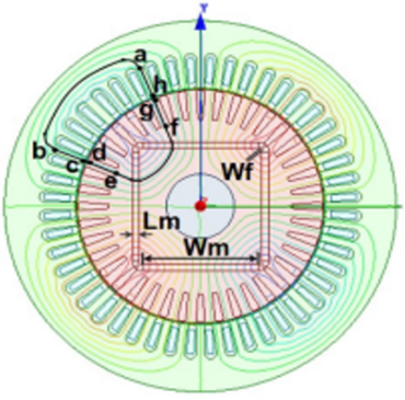
The performance of LSPMSM motors is actually dependent on permanent magnets. Thus, the modeling of magnets plays an important role in the design and analysis of local fields for these motors. The permanent magnets are often modeled in two forms [3], which are the magnetic vector modeling and equivalent current circuit modeling. To determine the working point on the magnetization characteristic line of a permanent magnet, it is necessary to consider the main magnetic flux line in the motor as presented in Figure 1.
Figure 1. Magnetic flux lines
where, Lab is the stator yoke length (Lsy), Lah and Lbc are the stator tooth height (Lst), Lhg and Lcd are the air gap, Lgf and Lde are the rotor tooth height (Ltr), Lfe is the rotort tooth length (Lry), Lm is the magnet thickness, Wm is the magnet width and Wf is the floating bridge distance. The details of the LSPMSM of 2.2 kW, with 36 stator slots and 28 rotor bars is given in Table 1. The geometry parameters of LS-PMSM can be investigated by two main parts (i.e., stator, rotor permanent magnet design) as given in Table 2. The rotor topology is determined during the design process by the design of stator windings. Finally, the placement of the required permanent magnets to the rotor core, makes the design process very practical.
Table 1. Main parameters of LSPMSM
|
Main Parameters |
Materials |
Weight (kg) |
|
Stator Lam (Back Iron) |
M800-50A |
12.92 |
|
Stator Lam (Tooth) |
M800-50A |
5.523 |
|
Stator Lamination [Total] |
18.44 |
|
|
Armature Winding [Active] |
Copper (Pure) |
2.67 |
|
Armature EWdg [Front] |
Copper (Pure) |
1.475 |
|
Armature EWdg [Rear] |
Copper (Pure) |
1.475 |
|
Armature Winding [Total] |
5.62 |
|
|
Magnet |
0.56 |
|
|
Rotor Lam (Back Iron) |
M800-50A |
4.326 |
|
Rotor Inter Lam (Back Iron) |
1.97E-05 |
|
|
Rotor Lam (Tooth) |
M800-50A |
4.468 |
|
Rotor Inter Lam (Tooth) |
2.04E-05 |
|
|
Rotor Lamination [Total] |
8.794 |
|
|
Rotor Cage Top Bar |
Aluminium (Cast) |
1.302 |
|
Rotor Cage Top Bar Opening |
Aluminium (Cast) |
0.01513 |
|
Rotor Cage (Front End) |
Aluminium (Cast) |
0.2962 |
|
Rotor Cage (Rear End) |
Aluminium (Cast) |
0.2962 |
|
Rotor Cage [Total] |
1.91 |
|
|
Shaft [Active] |
Iron (Pure) |
1.662 |
|
Flange Mounted Plate |
7.158 |
Table 2. Gemometry parameters of the LSPMSM
|
Sator parameters |
Quantity |
Rotor Parameters |
Quantity |
|
Slot Number |
36 |
Rotor Bars |
40 |
|
Stator Lam Diamention |
200 |
Pole Number |
4 |
|
Stator Bore |
122 |
Bar Opening |
1 |
|
Tooth Width |
6 |
Bar Opening Depth |
0.8 |
|
Slot Depth |
19.85 |
Rotor Tooth Width |
4.2 |
|
Slot Corner Radius |
3.7 |
Bar Depth |
20 |
|
Tooth Tip Depth |
1 |
Airgap |
0.45 |
|
Slot Opening |
2.5 |
Banding Thickness |
0.1 |
|
Tooth Tip Angle |
30 |
Shaft Dia |
41 |
|
Sleeve Thickness |
0.1 |
Shaft Hole Diameter |
32 |
This magnetic flux starts from the north pole of the magnet through the air gap, through the teeth and stator, then closes through the air gap through the teeth and cavities of the rotor. In this process, the word passes twice the magnet, twice the stator and rotor tooth length, twice the air gap and once the stator and rotor. In Figure 1, the magnetic circuit with the magnetic flux source is considered as a permanent magnet. By using Ampere's law, the nonlinear magnetic circuit is calculated through the dynamic magnetic forces falling on the main magnetic flux.
This process requires an additional magnetomotive force (MMF) falling throughout the circuit. It means that the EMFs of the magnet, stator, rotor, and air gap are enclosed in a loop circuit. Based on the B-H curve of electrical engineering steel, the flux density of air gap can be identified as:
$\oint H d l=2 H_m L_m+2 F_{t r}+2 F_{t s}+2 F_g+F_{s y}+F_{r y}=0$ (1)
By transforming from the Eq. 1, one gets [12, 19, 20]:
$2 H_m L_m+2 H_g g_e+2 H_{t r}\left(B_{t r}\right) l_{t r}+2 H_{t s}\left(B_{t s}\right) l_{t s}+H_{s y}\left(B_{s y}\right) l_{s y}+H_{r y}\left(B_{r y}\right) l_{r y}=0$ (2)
In addtion, from Figure 1, the magnetism of the permanent magnet is approximately the same as air, so the actual rotor length is only defined as $l_{r y}-2 L_m$. For that, one gets [19]:
$A=2 H_{t r}\left(B_{t r}\right) l_{t r}+2 H_{t s}\left(B_{t s}\right) l_{t s}+H_{s y}\left(B_{s y}\right) l_{s y}+H_{r y}\left(B_{r y}\right)\left(l_{r y}-2 L_m\right)$ (3)
where:
Hm: Magnetic field strength at the working point of the magnet (A/m);
Htr: Rotor tooth magnetic field strength (A/m);
Hts: Intensity from the head that stator (A/m);
Hsy: Magnetic field strength (A/m);
Hry: Rotor magnetic field strength (A/m);
Bts: Magnetic flux density of stator (T);
Btr: Rotorr tooth magnetic flux density (T);
Bsy: Magnetic flux density (T);
Bry: Rotorr magnetic flux density (T);
Ftr: Rotorr magnetic energy (A.T);
Fts: Magnetic stator (A.T);
Fsy: Magnetic stator (A.T);
Fry: Rotorr magnetic power (A.T);
Fg: Air gap dynamic magnetism (A.T).
Based on the Eq. (2) and Eq. (3), the magnetic flux density in air gap can be defined as [8-11]:
$B_g=-\frac{\mu_0}{2 g_e}\left(2 H_m L_m+A\right)=-\frac{\mu_0 H_m L_m}{g_e}-\frac{\mu_0 A}{2 g_e}$. (4)
The effective air gap (ge) is [11]:
$g_e=K_c g$
for $K_c=\left[1-\frac{b_{o s}}{\tau_s}+\frac{4 g}{\pi \tau_s} \ln \left(1+\frac{\pi b_{o s}}{4 g}\right)\right]^{-1}$ (5)
where, $\mu_0$ is the permeability of air gap: $\mu_0=4 \pi . 10^{-7} \mathrm{Tm} / \mathrm{A}$ and $t_s$ is the dental steps (m). Otherwise, one has
$\Phi_m=K_{l m} \Phi_g$. (6)
The leakage flux coefficient $\left(K_{l m}\right)$ in (6) is defined
$K_{l m}=1+\mu_{r m} \frac{g_e}{L_m} \frac{W_m}{W_m+g_e}(2 \eta+4 \lambda)$
$\eta=\frac{L_m}{\pi \mu_{r m} W_m} \ln \left(1+\frac{\pi g_e}{L_m}\right)$
$\lambda=\frac{L_m}{\pi \mu_{r m} W_m} \ln \left(1+\frac{\pi g_e}{W_f}\right)$ (7)
From the Eq. (7), one gets:
$B_m S_m=K_{l m} B_g S_g$ (8)
where, $S_m$ is the permanent magnet area and $S_g$ is the air gap area under one pole step.
By substituting the term of Bg in Eq. (4) and the leakage flux coefficient $K_{l m}$ in Eq. (7) into the equation Eq. (8), the magnet magnetic flux density of the working point is determined as follows.
$B_m=-\frac{\mu_0 L_m K_{l m} S_g}{S_m g_e} H_m-\frac{\mu_0 K_{l m} S_g A}{2 S_m g_e}$ (9)
The demagnetization characteristic line can be written as follows
$B=B_r+\mu_0 \mu_{r m} H$ (10)
where, $\mu_{r m}$ is the relative magnetic range of magnet. It should be noted that the working point of the permanent magnet is the intersection of the air gap line with the demagnetization line. For that, the magnetic field strength at the working point of the magnet is defined.
$H_m=\frac{B_m-B_r}{\mu_0 \mu_{r m}}$ (11)
By substituting equation (11) into equations (from (3) to (10)) with some transformations, one gets
$c B_m=d-e A \rightarrow B_m=\frac{d-e A}{c}$
for $c=\left(1+\frac{L_m K_{l m} \quad \alpha_i \tau}{W m g_e \mu_{r m}}\right)$
$d=\frac{L_m K_{l m} \quad \alpha_i \tau B_r}{W m g_e \mu_{r m}}, e=\frac{\mu_0 K_{l m} \quad \alpha_i \tau}{2 W m g_e}$ (12)
where, τ is the polar embrace, $\alpha_i$ is the magnetic flux density shape coefficient. According to some electrical machine design documents, the coefficient is usually determined empirically. In the case of LSPMSM motors, this coefficient depends on the degree of saturation of the electrical engineering steel and the shape of the density distribution of the air gap magnetic flux $\alpha_i$.
2.2 Flux density of rotor and stator tooth
The magnetic flux densities of rotor and stator parts under one pole embrace of the stator and rotor are enclosed through the stator tooth and the rotor tooth. The flux density is then calculated as follows:
$B_g=\frac{B_m S_m}{K_{l m} S_g}=\frac{B_m W_m}{K_{l m} \quad \alpha_i \tau}$ (13)
In the case of stators, it gets $\Phi_g^{\tau_s}=\Phi_{t s}$. Thus, the term of Bst is then defined as
$B_{t s}=\frac{B_g \tau_s L_s}{b_{t s} k_{F e} L_s}=\frac{B_g \tau_s}{b_{t s} k_{F e}}$, (14)
where, Ls is the stator effect length (m), $k_{F e}$ is the steel foil fastening coefficient and $b_{t s}$ is the stator tooth width (m).
By replacing the equation (13) with the equation (14), one has
$B_{t s}=\frac{W_m \tau_s}{\alpha_i \tau K_{l m} \quad b_{t s} k_{F e}} B_m \rightarrow B_{t s}=k_{s m} B_m$ (15)
where, the factor $k_{s m}$ is determined
$k_{s m}=\frac{W_m \tau_s}{\alpha_i \tau K_{l m} \quad b_{t s} k_{F e}}$ (16)
In the case of rotor, it gets $\Phi_g^{\tau_s}=\Phi_{t r}$. Thus, the term of Btr is then defined as
$B_{t r}=\frac{B_g \tau_r L_s}{b_{t r} k_{F e} L_s}=\frac{B_g \tau_r}{b_{t r} k_{F e}}$ (17)
where, $b_{t r}$ is the rotor tooth width (m).
By replacing the Eq. (16) with the Eq. (17), one gets
$B_{t r}=\frac{W_m \tau_s}{\alpha_i \tau K_{l m} \quad b_{t s} k_{F e}} B_m \rightarrow B_{t r}=k_{r m} B_m$ (18)
where, the factor $k_{r m}$ is determined
$k_{r m}=\frac{W_m \quad \tau_r}{\alpha_i \tau K_{l m} \quad b_{t r} k_{F e}}$ (19)
Thetically, the half of air gap magnetic flux under per one pole through the stator and rotor can be considered in two cases of stator and rotor to find out the stator yoke fator ($k_{s y m}$) and the rotor yoke factor ($k_{r y m}$). In the case of stators, one gets $\Phi_g^\tau=\Phi_{s y}$.
$B_{s y} S_{s y}=\frac{1}{2} B_g \tau L_s \rightarrow B_{s y} h_{s y} L_s k_{F e}=\frac{1}{2} B_g \tau L_s \rightarrow B_{s y} h_{s y} k_{F e}=\frac{1}{2} B_g \tau$ (20)
where, $S_{s y}$ is the stator area and $h_{s y}$ is the stator height.
By replacing the expression (19) with the expression (20), one has
$B_{s y}=\frac{W_m}{2 K_{l m} \alpha_i h_{s y} \quad k_{F e}} B_m \rightarrow B_{s y}=k_{s y m} B_m$ (21)
where, the fator $k_{s y m}$ is expressed as
$k_{s y m}=\frac{W_m}{2 K_{l m} \alpha_i h_{s y} \quad k_{F e}}$ (22)
In the case of rotor, it gets: $\Phi_g^\tau=\Phi_{r y}$. For that one gets
$B_{r y} S_{r y}=\frac{1}{2} B_g \tau L_s \rightarrow B_{r y} h_{r y} L_s k_{F e}=\frac{1}{2} B_g \tau L_s \rightarrow B_{r y} h_{r y} k_{F e}=\frac{1}{2} B_g \tau$ (23)
where, $S_{r y}$ is the rotor area and is the rotor height.
By substituting (22) into (23), it can be defined as
$B_{r y}=\frac{W_m}{2 K_{l m} \quad \alpha_i h_{r y} \quad k_{F e}} B_m \rightarrow B_{r y}=k_{r y m} B_m$ (24)
where, the factor $k_{r y m}$ can be defined as
$k_{r y m}=\frac{W_m}{2 K_{l m} \quad \alpha_i h_{r y} \quad k_{F e}}$ (25)
These design factors of krm, ksm, ksy and kry are relationship of stator, rotor teeth and yokes with magnetic flux density at operation points, respectively. Those parameters have built from many electromagnetic calculations.
Two cases of LSPMSM of 2.2kW are considered. Each case proceeds to change the width Wm and length Lm of the permanent magnet. Figure 2 shows the rotor groove structure (left), stator groove (right) of 2.2kW motor.
Figure 2. Rotor groove structure (left), stator groove (right) of LSPMSM of 2.2kW
where, the dimensions the rotor groove are given as: ho=0.4 mm, h1=1.4 mm, dl=3.89 mm, d2=1.99 mm, hr=12 mm. The dimensions of the stator groove are: hos=1 mm, h12=12.4 mm, bos=2.9 mm, dl=3.71 mm, d2=5.3 mm, and hs=13.6 mm.
-For case 1: Lm=2 mm; Wm=54mm.
-For case 2: Lm=3 mm; Wm=51mm.
Analysis results of the two cases are illustrated in Figure 3.
The results of the comparison between the analytic and FEM methods are illustrated in Table 3.
Figure 3. Case structure 1 (left), case structure 2 (right)
Table 3. Results of comparison between the two methods
|
Different methods |
Bm |
Bg |
||
|
Case 1 |
Case 2 |
Case 1 |
Case 2 |
|
|
Analytical |
0.891 |
0.952 |
0.485 |
0.496 |
|
FEM |
0.925 |
0.990 |
0.490 |
0.499 |
|
Error (%) |
3.479 |
3.466 |
0.618 |
0.639 |
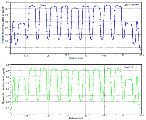
It can be seen that the analytical result is very similar to the result of finite eleement method (FEM) [21]. The error of the air gap flux density Bg in both analytical and FEM methods is 0.618%. This means that the obtained results from the analytic method is quite accurate. For that, t is useful to design and optimize the electromagnetic parameters of LSPMSM. The flux density distribution for case 1 and 2 are pointed out in Figure 4.
Figure 4. Magnetic flux density in air gaps for case 1 (top) and case 2 (bottom)
In order to evaluate the air gap flux density Bg, the magnetic thickness Lm is changed from 2.8 mm to 4.8mm. For that, each case is 1mm increasing.
The magnetic flux density Bg is increased from 0.1415 T to 0.1428 T, while the magnet thickness is from 2.8 mm to 4.8mm, but the waveforms of magnetic flux density are the similar profiles as presented in Figure 5. The waveforms of magnet thickness of 2.8 mm, 3.8mm and 4.8mm are same characteristics or shapes. Table 4 shows the flux density results with different thicknesses (Lm).
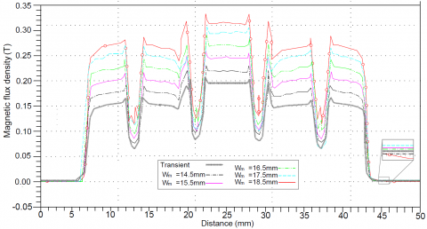
The flux density Bg is increased with the magnetic width Wm with each step of 1mm. The air gap flux density distribution with different magnetic widths is presented in Figure 6.
Figure 5. Air gap flux density with different magnetic thickness
Table 4. Magnetic flux density results with different thicknesses (Lm)
|
Lm (mm) |
Bg (T) |
|
2.8 |
0.1415 |
|
3.8 |
0.1425 |
|
4.8 |
0.1428 |
The flux density Bg is increased with the magnetic width Wm with each step of 1mm. The air gap flux density distribution with different magnetic widths is presented in Figure 6.
Figure 6. Air gap flux density distribution with different magnetic widths
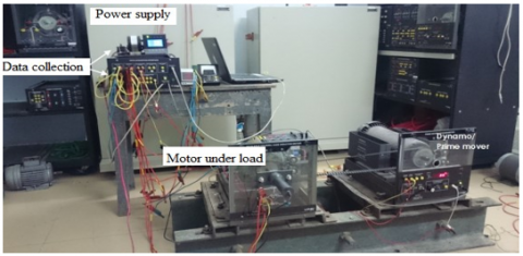
Model of the designed motor is shown in Figure 7. An experimental test bench has built to evaluate back electromagnetic force at different speeds.
Figure 7. Stator (a), Rotor (b), Rotor drawing (c) and Rotor assembly (d)
Figure 8. Model of motor test bench
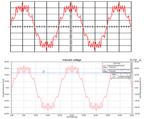
Figure 9. Back EMF measured by Osiloscope with 20V/div and 5ms/div (top) and back EMF simulation and measurement comparison (bottom)
The no load voltage of three stator windings is measured at the different speeds of 500 and 750 rpm. The back electromagnetic force (EMF) waveform are displayed in Ossiloscope with DAI-Labvol interation as shown in Figure 8. The back EFM waveforms of simulation and experiment result are quite good agreement as presented in Figure 9.
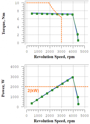
The current and voltage waveforms were compared together at rated speed by measurement and FEM simulation methods in Figure 10. The torque, efficiency and power have been compared with different methods (analytic, FEM and experimental methods). The obtained results are shown in Figures (from Figure 10 and Figure 11). It can be seen that the measured results are checked to be very close to the torque, EMF, current and power obtained by the FEM method.
Figure 10. Back EMF measured by Osiloscope with 100V/div-2A/div and 5ms/div (top) and back EMF and current I simulated by FEM (bottom)
Figure 11. Comparison of torque and power simulations and measurement
The LSPMSM in this paper is consideered with I magnet shape and curve flux barrier. The flux density structure of this machine is developed from a convention induction motor. The total torque is combined of magnetic torque and rotor cage torque characteristics. In compared with other induction motors, the LSPMS motor can improve efficiency by eleminating the rotor cage loss at the synchronous speed.
This study has found out an analytical calculation of the flux density distribution of air gap, stator and rotor poles, yokes with very high accuracy. To validate the performed analytical design, the designed motor is modeled by using the FEM in Maxwell software. The motor behavior and characteristics are investigated in steady state using magnetostatic analysis as well as transient state by the transient analysis of Maxwell software. The results of FEM has been confirmed that the analytical design results are the good agreement between both methods for torque, efficiency and flux density quantities. The torque curves can keep as a constant with the basic speed up to 4000rpm to ensures that this machine can apply for an electric traction in practice.
This research is funded by Hanoi University of Science and Technology (Grant No.: T2022-PC-009).
[1] Waheed, A., Kim, B., Cho, Y.H. (2020). Optimal design of line-start permanent magnet synchronous motor based on magnetic equivalent parameters. J. Electr. Eng. Technol, 15: 2111-2119.
https://doi.org/10.1007/s42835-020-00464-z
[2] Edjtahed, S.H., Seadati, S.A.S., Niasar, A.H., Ahmadi, M. (2017). Analytical design and finite element analysis of high speed, axial-flux permanent magnet synchronous motor. In 2017 8th Power Electronics, Drive Systems & Technologies Conference (PEDSTC), pp. 235-240. https://doi.org/10.1109/PEDSTC.2017.7910329
[3] Bo, Y., Wang, X.H., Yang, Y.B. (2019). Parameters determination and dynamic modelling of line-start permanent-magnet synchronous motor with a composite solid rotor. IET Electric Power Applications, 13(1): 17-23. https://doi.org/10.1049/iet-epa.2018.5064
[4] De Almeida, A.T., Ferreira, F.J.T.E.T.E., Fong, J.A.C. (2011). Standards for efficiency of electric motors. In IEEE Industry Applications Magazine, 17(1): 12-19. https://doi.org/10.1109/MIAS.2010.939427
[5] Isfahani, A.H., Vaez-Zadeh, S. (2009). Line start permanent magnet synchronous motors: Challenges and opportunities. Energy, 34(11): 1755-1763. https://doi.org/10.1016/j.energy.2009.04.022
[6] Mi, C.T., Filippa, M., Liu, W.G., Ma, R.Q. (2004). Analytical method for predicting the air-gap flux of interior-type permanent-magnet machines. IEEE Transactions on Magnetics, 40(1): 50-58. https://doi.org/10.1109/TMAG.2003.821562
[7] Jean-Pierre, E., Sorgdrager, A.J., Wang, R.J. (2014). A study of rotor typologies of line-start PM motors for cooling fan applications. In Proceedings of the 22nd South African Universities Power Engineering Conference, pp. 284-289. https://doi.org/10.13140/2.1.2238.8482
[8] Shehata, E.G. (2014). Design tradeoffs between starting and steady state performances of line-started interior permanent magnet synchronous motor. In 7th IET International Conference on Power Electronics, Machines and Drives (PEMD 2014), pp. 1-6. https://doi.org/10.1049/cp.2014.0281
[9] Stumberger, B., Marcic, T., Hadziselimovic, M. (2012). Direct comparison of induction motor and line-start ipm synchronous motor characteristics for semi-hermetic compressor drives. In IEEE Transactions on Industry Applications, 48(6): 2310-2321. https://doi.org/10.1109/TIA.2012.2227094
[10] Raja. V., Bhaskaran. M. (2013). Improving the performance of genetic algorithm by reducing the population size. International Journal of Emerging Technology and Advanced Engineering, 8: 86-91.
[11] Lu, W., Luo, Y., Zhao, H. (2012). Influences of rotor bar design on the starting performance of line-start permanent magnet synchronous motor. In 2012 Sixth International Conference on Electromagnetic Field Problems and Applications, pp. 1-4. https://doi.org/10.1109/ICEF.2012.6310360
[12] Fei, W., Luk, P.C.K., Ma, J., Shen, J.X., Yang, G. (2009). A high-performance line-start permanent magnet synchronous motor amended from a small industrial three-phase induction motor. In IEEE Transactions on Magnetics, 45(10): 4724-4727. https://doi.org/10.1109/TMAG.2009.2022179
[13] Ogbuka, C., Nwosu, C., Agu, M. (2016). Performance comparison of line-start permanent magnet synchronous motors with interior and surface rotor magnets. Indian Journal of Science and Technology, 9(4): 72038. https://doi.org/10.17485/ijst/2016/v9i4/72038
[14] Ugale, R., Chaudhari, B., Pramanik, A. (2014). Overview of research evolution in the field of line start permanent magnet synchronous motors. Electric Power Applications, 8: 141-154. https://doi.org/10.1049/iet-epa.2013.0241
[15] Dinh, B.M. (2017). Optimal rotor design of line start permanent magnet synchronous motor by genetic algorithm. Adv. Sci. Technol. Eng. Syst. J., 2: 1181-1187. https://doi.org/10.25046/aj0203149
[16] Ding, T., Takorabet, N., Sargos, F.M., Wang, X. (2009). Design and analysis of different line-start pm synchronous motors for oil-pump applications. IEEE Transactions on Magnetics, 45(3): 1816-1819. https://doi.org/10.1109/TMAG.2009.2012772
[17] Huang, P.W., Mao, S.H., Tsai, M.C., Liu, C.T. (2008). Investigation of line start permanent magnet synchronous motors with interior-magnet rotors and surface-magnet rotors. In 2008 International Conference on Electrical Machines and Systems, pp. 2888-2893.
[18] Xu, X.Z. (2013). Performance of line-start permanent magnet synchronous motor with novel rotor structure. International Journal of Digital Content Technology and its Applications, 7: 1217-1225. https://doi.org/10.4156/jdcta.vol7.issue6.139
[19] Feng, X., Liu, L., Kang, J., Zhang, Y. (2010). Super premium efficient line start-up permanent magnet synchronous motor. In the XIX International Conference on Electrical Machines - ICEM 2010, pp. 1-6. https://doi.org/10.1109/ICELMACH.2010.5608107
[20] Bao, Y., Liu, L., Zhang, Y., Feng, X. (2011). Performance investigation and comparison of line start-up permanent magnet synchronous motor with super premium efficiency. In 2011 International Conference on Electrical Machines and Systems, pp. 1-6. https://doi.org/10.1109/ICEMS.2011.6073590
[21] Dang, V.Q., Geuzaine, C. (2020). Two-way coupling of thin shell finite element magnetic models via an iterative subproblem method. The international journal for computation and mathematics in electrical and electronic engineering, 39(5): 1085-1097. https://doi.org/10.1108/COMPEL-01-2020-0035