P Shivakumar* | S K Barik
© 2022 IIETA. This article is published by IIETA and is licensed under the CC BY 4.0 license (http://creativecommons.org/licenses/by/4.0/).
OPEN ACCESS
Multilevel inverters are a novel type of dc–ac converter designed for medium and high voltage and power applications. Cascaded multilevel inverters are the most common inverters used in renewable energy applications. Despite the numerous advantages, the presence of extra circuit components in the design causes reliability concerns with these inverters. Researchers have faced a significant difficulty in constructing inverters with improved dependability by lowering total harmonic distortion (THD). This paper proposes a concept of Grid connected PV system with multilevel inverter topology. The PV system is implemented by using mathematical analysis and MPPT based dc-dc boost converter is used to improve the performance of PV system. In this paper, perturb and observe MPPT technique is implemented. For obtaining better harmonic distortions and proper synchronization with grid a multi-level inverter is implemented. This paper proposes a novel multilevel inverter topology for renewable energy operations which produces 31 and 51 level output voltages. The conventional topology is formed with 10 IGBT switches. A closed loop controller with sinusoidal pulse width modulation technique is implemented to generate gate signals required for 31-Level converter. The 51-Level converter is modelled with 8-IGBT switches and 4-diodes, also space vector and sinusoidal pulse width modulation techniques are used to generate the gate signals for switches. This proposed system is tested and verified in MATLAB and a comparative analysis made between sinusoidal and space vector modulation in 51-Level topology.
photovoltaic (PV), 51 level multi-level inverter, total harmonic distortion (THD)
In the present scenario, rapid growth in population and continuous changes in load demand, the existing power plant fails to meet this requirement. To overcome this problems, renewable energy systems is an alternative solution in the power generation system. The available energy systems in the RES family is Solar, Wind, Fuel and Hydro systems. Out of all systems based on the available environment conditions photovoltaic systems is the effective solution. The photovoltaic system converts solar radiation and temperature into electrical energy. The main problem in the solar energy system is that the generation of electrical energy is very low.
The day to day increase of population and rapid changes in utilization of electrical power causes deficiency in generation demand. The alternate renewable energy sources help to meet these requirements. The photovoltaic system plays a key role in distributed energy sources (non-conventional sources) because of freely available in nature and its high reliability. An MPPT based dc-dc converter is implemented to improve the reliability of PV system [1]. The voltage source converter helps to maintain proper synchronization between PV and Grid system. The reference signal for dc-dc converter generated using MPPT controller.
As the output from PV system is in DC nature, so inverter is required to convert it into AC mode. The main disadvantage of basic classical inverter produces high amount of harmonic distortion. The possible solution to get low harmonics is to implement a multi-level inverter. Multilevel inverter has planted their place in medium and high-power applications such as Var-Compensators, motor drives and controlling equipment. As the input of inverter is DC, solar cell, fuel cell and ultra-capacitor based cells are used as input sources and combination of dc sources are taken to generate multi-level output voltages.
In general, as compared with conventional inverter, the multi-level converter has the advantage i.e obtaining multi voltage levels with reduced switch count. As the voltage level number is increases to reach near shape of sinusoidal waveform with lower harmonic order [2, 3]. MLIs are a combination of power semiconductor devices and various dc linkages that produce a staircase waveform that is close to sinusoidal at the output. The three basic and popular MLI topologies utilised in commercial applications over the last few decades are Neutral Point Clamped (NPC), Flying Capacitor (FC), and Cascade H-Bridge (CHB). Although the standard MLI has a few drawbacks, such as a higher number of source requirements, capacitor voltage balancing, and big switch requirements in the CHB, FC, and NPC topologies, respectively [4, 5].
As these topologies required more switching count and produce higher harmonic level. In order to overcome these problems, this paper proposes new topology converter with reduced switches and generate 31 and 51 level voltages. A suitable sinusoidal and space vector modulated techniques implemented for generating gate signals for multi-level converter [6]. These proposed systems are tested in MATLAB under different load conditions and compared the harmonic analysis.
This article proposes in the following manner. The section -2 shows the complete operation of grid connected PV system. Section-3 shows the operation of 51-Level Inverter, section-4 gives the simulation analysis of proposed system under different loads and final section shows about conclusion of the article [7].
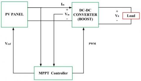
Grid interfaced solar system with multi-level inverter is shown in Figure 1 [8]. The architecture consists of the following components namely, a) PV System, b) MPPT based DC-DC Boost converter and c) Modulation technique based multi-level converter for generating multi output voltage levels. In this Perturb and Observe MPPT technique is chosen.
Figure 1. Proposed multi-level inverter with PV system
2.1 Photovoltaic system
The PV system is a set of series and parallel connected solar cells to meet the requirement of panel. The output from the solar is not constant as it is depending on the climate conditions [9]. The main components in the proposed system are a) DC-DC converter based PV system controlled by MPPT technique, b) Wind Energy System with dc-dc converter, c) PWM based Inverter.
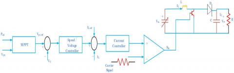
The MPPT based DC-DC converter required for PV system as shown in Figure 2. In this MPPT controller generates the reference signal based on the PV voltage and current [10]. This reference signal is compared with actual signal from the converter which is applied to PWM controller to generate suitable gate signal for dc-dc converter [11]. The PV system power depends up on natural climatic conditions, in order to get the maximum power from the solar PV, we need to tune the duty cycle such a way that applied to the gate pulse of MOSFET/IGBT switch used in boost converter. The duty cycle signal generated after comparing the MPPT voltage signal and reference voltage signal [12].
Figure 2. Control structure of DC-DC converter with PV system
The Photovoltaic current for solar cell is expressed as:
$I=I_{p h}-I_{o}\left(e^{\frac{q\left(v+I R_{s}\right)}{N K T}}-1\right)-\frac{\left(v+I R_{s}\right)}{R_{s h}}$ (1)
Figure 3, shows the closed loop controller for DC-DC boost converter of PV system. The Reference signal for modulation technique is generated using PV voltage and current parameters called as MPPT [13] controller.
Figure 3. Control structure of DC-DC converter with PV system
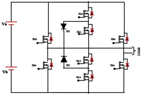
In Figure 4, shows the topology for 51-Level converter, which consists of reduced switches with 8 bi-directional switches and 4-unidirectional switches. The gate pattern required for 8 (Eight) switches are generated and made a comparison with two modulation techniques. The proposed 51-Level topology consists of 2 (Two) isolated dc sources Va, Vb, with 8 power electronic switches SA1, SA2, SA3, SA4, SB1, SB2, SB3, SB4, and two diodes D1, D2 [14, 15]. This asymmetrical multilevel Inverter topology produces 51 levels, i.e., 25 positive levels, 25 negative situations and a zero level. The positive terminal of the switch is connected between the switches SB2, SB4 and negative switches connected between the switches SB1, SB3. Diode D1 is conducted for positive cycle and D2 conduct for negative part [16, 17].
The equations for identifying the number of switches, gate driver circuits and number of voltage are shown below:
Nsw=2k+4
Ngd=3k+4
Nl=25k+1 (2)
The peak Output Voltage is given by:
Vo,m=(12k+1)Vdc (3)
Figure 4. 51-level converter based on the proposed topology with two cascaded basic units
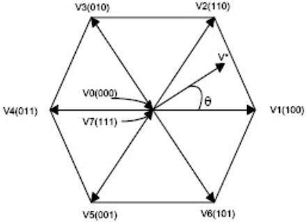
3.1 Space vector modulation technique
Space vector modulation based technique is one of the type in pulse modulation techniques has the advantage of low harmonic content [18, 19]. In this technique the reference signal is divided in to eight vector components namely V0, V2, V3 and . . . V7. Here, V0 and V7 vectors called as null vectors and V1 to V6 vectors are decide the switching sequence of switches in converter.
In Figure 5, the vector V1 has coordinates of (1,0,0) which decides that Phase-a is in “ON” position while phase-b and phase-c are in “OFF” position [20, 21]. The required pulse width is identified by considering the position of particular reference signal between the two vectors during a period of time. The expression for calculating pulse width is identified by the following time duration T1, T2 and T0. The switching sequence for proposed 51-Level Inverter is shown in Table 1.
The reference signals for voltages and V0 to V7 and switch-ing time sequences are generated by the following expression [22, 23]:
$V * T_{z}=\left(V_{1} * T_{1}\right)+\left(V_{2} * T_{2}\right)+\left(V_{o} *\left(\frac{T_{0}}{2}\right)\right)+\left(V_{7} *\left(\frac{T_{o}}{2}\right)\right)$ (4)
Figure 5. Space vector modulation technique
Table 1. Switching state of proposed 51-level inverter
|
Voltage |
|
Name and state of Switches |
|
||
|
Level |
SA1, SA2 |
SA3, SA4 |
SB1, SB2 |
SB3, SB4 |
D1 ,D2 |
|
0 |
1, 1 |
0, 0 |
0, 0 |
1, 0 |
1, 0 |
|
1 |
0, 1 |
1, 0 |
0, 0 |
1, 0 |
1, 0 |
|
2 |
1, 0 |
0, 1 |
0, 0 |
1, 0 |
1, 0 |
|
3 |
1, 0 |
0, 1 |
0, 0 |
1, 1 |
1, 0 |
|
4 |
0, 0 |
1, 0 |
1, 1 |
0, 0 |
1, 0 |
|
5 |
0, 1 |
0, 1 |
1, 0 |
1, 0 |
1, 0 |
|
6 |
1, 0 |
0, 1 |
0, 1 |
1, 0 |
1, 0 |
|
7 |
1, 0 |
1, 0 |
0, 1 |
1, 0 |
1, 0 |
|
8 |
0, 1 |
1, 0 |
1, 0 |
1, 0 |
1, 0 |
|
9 |
0, 1 |
0, 0 |
0, 0 |
0, 1 |
1, 0 |
|
10 |
0, 1 |
0, 0 |
1, 0 |
0, 1 |
1, 0 |
|
11 |
1, 0 |
1, 0 |
0, 1 |
0, 1 |
1, 0 |
|
12 |
1, 0 |
0, 1 |
0, 0 |
0, 1 |
1, 0 |
|
13 |
0, 1 |
0, 0 |
1, 0 |
1, 0 |
1, 0 |
|
14 |
0, 0 |
0, 1 |
0, 0 |
1, 0 |
1, 0 |
|
15 |
1, 0 |
1, 0 |
0, 1 |
0, 1 |
1, 0 |
|
16 |
0, 0 |
1, 0 |
1, 0 |
0, 0 |
1, 0 |
|
17 |
0, 1 |
0, 0 |
1, 1 |
0, 1 |
1, 0 |
|
18 |
1, 0 |
0, 1 |
0, 0 |
1, 0 |
1, 0 |
|
19 |
0, 1 |
0, 0 |
1, 0 |
1, 0 |
1, 0 |
|
20 |
0, 1 |
1, 0 |
1, 0 |
0, 1 |
1, 0 |
|
21 |
0, 0 |
0, 1 |
0, 1 |
1, 0 |
1, 0 |
|
22 |
0, 0 |
0, 1 |
1, 0 |
1, 0 |
1, 0 |
|
23 |
1, 0 |
1, 0 |
0, 1 |
0, 1 |
1, 0 |
|
24 |
0, 1 |
0, 0 |
0, 0 |
1, 1 |
1, 0 |
|
25 |
0, 0 |
0, 0 |
1, 0 |
1, 0 |
1, 0 |
|
-1 |
0, 0 |
0, 1 |
1, 0 |
0, 1 |
0, 1 |
|
-2 |
0, 0 |
1, 1 |
0, 1 |
0, 0 |
0, 1 |
|
-3 |
1, 0 |
0, 1 |
0, 1 |
0, 1 |
0, 1 |
|
-4 |
0, 0 |
1, 1 |
0, 0 |
0, 0 |
0, 1 |
|
-5 |
1, 0 |
0, 1 |
0, 0 |
0, 1 |
0, 1 |
|
-6 |
0, 1 |
0, 0 |
1, 0 |
0, 1 |
0, 1 |
|
-7 |
0, 1 |
1, 0 |
0, 0 |
0, 0 |
0, 1 |
|
-8 |
1, 1 |
0, 0 |
0, 0 |
1, 1 |
0, 1 |
|
-9 |
0, 0 |
0, 0 |
1, 1 |
1, 0 |
0, 1 |
|
-10 |
0, 0 |
1, 0 |
0,1 |
1, 0 |
0, 1 |
|
-11 |
1, 0 |
0, 0 |
0, 1 |
1, 0 |
0, 1 |
|
-12 |
0, 0 |
0, 1 |
1, 0 |
1, 0 |
0, 1 |
|
-13 |
0, 0 |
1, 1 |
0, 0 |
1, 0 |
0, 1 |
|
-14 |
1, 0 |
0, 1 |
0, 0 |
1, 0 |
0, 1 |
|
-15 |
0, 1 |
0, 0 |
1, 0 |
1, 0 |
0, 1 |
|
-16 |
0, 1 |
1, 0 |
0, 1 |
0, 1 |
0, 1 |
|
-17 |
1, 1 |
0, 0 |
0, 1 |
0, 1 |
0, 1 |
|
-18 |
1, 0 |
0, 0 |
1, 0 |
0, 1 |
0, 1 |
|
-19 |
0, 1 |
0, 0 |
0, 1 |
0, 1 |
0, 1 |
|
-20 |
0, 0 |
0, 1 |
1, 0 |
0, 1 |
0, 1 |
|
-21 |
0, 0 |
1, 1 |
0, 0 |
0, 1 |
0, 1 |
|
-22 |
1, 0 |
0, 1 |
0, 0 |
0, 1 |
0, 1 |
|
-23 |
0, 1 |
0, 0 |
1, 0 |
0, 1 |
0, 1 |
|
-24 |
0, 1 |
1, 0 |
0, 0 |
0, 1 |
0, 1 |
|
-25 |
1, 1 |
0, 0 |
0, 0 |
0, 1 |
0, 1 |
The expressions for calculations of switching and conduction losses for both IGBT and diode are shown below:
$P_{s}=\left[V_{s}+R_{s} i^{\beta}(t)\right] i(t)$ (5)
$P_{D}=\left[V_{D}+R_{D} i^{\beta}(t)\right] i(t)$ (6)
$P_{s w, s}=\left[E_{o n}+E_{o f f}\right] f_{s w}$ (7)
$P_{s w, D}=\left[E_{o n, D}+E_{o f f, D f}\right] f_{s w}$ (8)
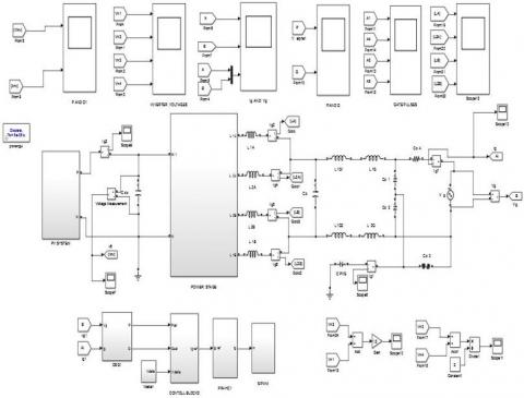
This proposed system is tested using the Matlab Software. Simulink diagram for Transformer less inverter for grid tied PV Systems as shown in Figure 6.
Figure 7 shows the simulation results for grid voltage and current measured at variable reactive load. Here a step change reactive load is applied to the system and corresponding change in grid current is measured. Figure 8, shows the simulation results for common mode voltages for four phase terminals with respect to neutral.
Figure 6. Simulation diagram for proposed HERIC converter
Figure 7. Simulation result for grid voltage and current
Figure 8. Simulation result for CM voltages
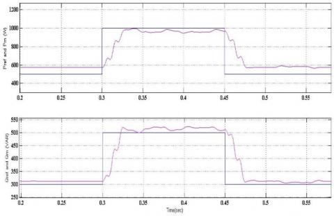
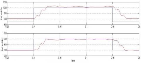
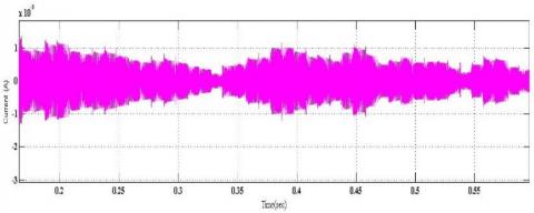
The reference and measured waveforms for system active and reactive powers are shown in Figure 9 before compensation. After implementation of 51-Level inverter topology the distortions between measure and reference reactive power is reached nearly as shown in Figure 10. The waveform for leakage current through capacitor is shown in Figure 11.
Figure 9. Simulation result for grid active & reactive powers with PR controller
Figure 10. Simulation result for grid active & reactive powers with proposed converter topology
Figure 11. Simulation result for leakage current
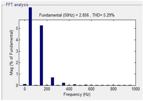
Figure 12. THD for inverter current using PR controller
Figure 12 and 13 shows the simulation FFT analysis for total harmonic distortion under PR controller and proposed space vector modulation based 51-Level multilevel inverter.
Figure 13. THD for Inverter current using proposed converter topology
Much more research had been undertaken to design multilevel inverters with reduced circuit components, minimum losses, low cost, and compact size with high efficiency. A survey is made in this paper to identify the type of multilevel inverter used in high and medium power applications such as Electric Vehicle, Power drives, Grid integration systems, etc. A detailed review is conducted on the recent multilevel inverter design with reduced switch count to find out the challenges and key issues. Significant issues of various multilevel inverter designs are provided in terms of number of diodes, switches, source utilization and filter requirement. This study proposes a transformerless HERIC converter for grid-connected PV systems. A suitable control strategy is created with traditional PR and SVM based 51-Level MLI to manage the reactive power of this system and reduce the harmonics in this system. MATLAB/Simulink was used to successfully test and verify the proposed system. According to these simulation results, the SVM controller achieves superior harmonic compensation and reactive power control than the standard PR controller.Much more research had been undertaken to design multilevel inverters with reduced circuit components, minimum losses, low cost, and compact size with high efficiency. A survey is made in this paper to identify the type of multilevel inverter used in high and medium power applications such as Electric Vehicle, Power drives, Grid integration systems, etc. A detailed review is conducted on the recent multilevel inverter design with reduced switch count to find out the challenges and key issues. Significant issues of various multilevel inverter designs are provided in terms of number of diodes, switches, source utilization and filter requirement. This study proposes a transformerless HERIC converter for grid-connected PV systems. A suitable control strategy is created with traditional PR and SVM based 51-Level MLI to manage the reactive power of this system and reduce the harmonics in this system. MATLAB/Simulink was used to successfully test and verify the proposed system. According to these simulation results, the SVM controller achieves superior harmonic compensation and reactive power control than the standard PR controller.
[1] Babaei, E., Kangarlu, M.F., Hosseinzadeh, M.A. (2013). Asymmetrical multilevel converter topology with reduced number of components. IET Power Electronics, 6(6): 1188-1196.
[2] Corzine, K., Familiant, Y. (2002). A new cascaded multilevel H-bridge drive. IEEE Transactions on Power Electronics, 17(1): 125-131. https://doi.org/10.1109/63.988678
[3] Rajyalakshmi, P., Praveen, V. (2018). Asymmetric cascaded half bridge multi level inverter with permanent magnet synchronous motor (PMSM).
[4] McGrath, B.P., Holmes, D.G. (2009). Natural capacitor voltage balancing for a flying capacitor converter induction motor drive. IEEE Transactions on Power Electronics, 24(6): 1554-1561. https://doi.org/10.1109/TPEL.2009.2016567
[5] Babaei, E. (2008). A cascade multilevel converter topology with reduced number of switches. IEEE Transactions on Power Electronics, 23(6): 2657-2664. https://doi.org/10.1109/TPEL.2008.2005192
[6] Ganesh, L.K., Sarma, S.S.S., Zubear, M.D., Ramaiah, K.D., Balaji, R. (2019). Performance evaluation of novel grid tied 21 level asymmetrical MLI topology using advanced PWM. Methodologies. Journal of Applied Science and Computations, 1397-1408.
[7] Ebrahimi, J., Babaei, E., Gharehpetian, G.B. (2011). A new topology of cascaded multilevel converters with reduced number of components for high-voltage applications. IEEE Transactions on Power Electronics, 26(11): 3109-3118. https://doi.org/10.1109/TPEL.2011.2148177
[8] Saeedifard, M., Barbosa, P.M., Steimer, P.K. (2011). Operation and control of a hybrid seven-level converter. IEEE Transactions on Power Electronics, 27(2): 652-660. https://doi.org/10.1109/TPEL.2011.2158114
[9] Pulikanti, S.R., Konstantinou, G.S., Agelidis, V.G. (2012). Generalisation of flying capacitor-based active-neutralpoint-clamped multilevel converter using voltage-level modulation. IET Power Electronics, 5(4): 456-466.
[10] Kangarlu, M.F., Babaei, E., Laali, S. (2012). Symmetric multilevel inverter with reduced components based on non-insulated dc voltage sources. IET Power Electronics, 5(5): 571-581. https://doi.org/10.1049/iet-pel.2011.0263
[11] Rodriguez, J., Lai, J.S., Peng, F.Z. (2002). Multilevel inverters: A survey of topologies, controls, and applications. IEEE Transactions on Industrial Electronics, 49(4): 724-738. https://doi.org/10.1109/TIE.2002.801052
[12] Babaei, E., Hosseini, S.H. (2009). New cascaded multilevel inverter topology with minimum number of switches. Energy Conversion and Management, 50(11): 2761-2767. https://doi.org/10.1016/j.enconman.2009.06.032
[13] Gonzalez, S.A., Valla, M.I., Christiansen, C.F. (2010). Five-level cascade asymmetric multilevel converter. IET Power Electronics, 3(1): 120-128. https://doi.org/10.1049/iet-pel.2008.0318
[14] Reddy, K.P.K., Vasulu, B. (2017). A multi boost and full bridge converters for power management for hybrid vehicle by battery and super capacitors. International Journal for Modern Trends in Science and Technology, 3(1): 187-192.
[15] Karthikumar, K., Karuppiah, M., Arunbalaj, A., Krishnakumar, S., Sathyanathan, P. (2006). Implementation of parameters monitoring and controlling system using wireless communication. ARPN Journal of Engineering and Applied Sciences, 12(13): 4175-4181.
[16] Lienhardt, A.M., Gateau, G., Meynard, T.A. (2005). Stacked multicell converter (SMC): reconstruction of flying capacitor voltages. Proc. IECON, 2005, pp. 691-696. http://dx.doi.org/10.1109/IECON.2005.1568988
[17] Reddy, G.R., Rayaguru, N.K., Karthikumar, K., Chandrasekar, P., Murthy, P.S.S.N. (2021). Enhancement of power quality with fuzzy based UPQC in grid integrated and battery assisted PV system. In 2021 2nd Global Conference for Advancement in Technology (GCAT), Bangalore, India, pp. 1-8. https://doi.org/10.1109/GCAT52182.2021.9587595
[18] McGrath, B.P., Holmes, D.G. (2008). Analytical modelling of voltage balance dynamics for a flying capacitor multilevel converter. IEEE Trans. Power Electron., 23(2): 543-550. https://doi.org/10.1109/TPEL.2007.915175
[19] Karthikumar, K., Senthil Kumar, V. (2021). A new opposition crow search optimizer-based two-step approach for controlled intentional islanding in microgrids. Soft Computing, 25(4): 2575-2588. https://doi.org/10.1007/s00500-020-05280-1
[20] Rayaguru, N., Sekar, S. (2021). A hybrid: ant lion optimization-cuckoo search based mppt algorithm for grid connected solar system. Journal of Green Engineering, 11(2): 1153-1176.
[21] Manjrekar, M.D., Lipo, T.A. (1998). A hybrid multilevel inverter topology for drive applications. In APEC'98 Thirteenth Annual Applied Power Electronics Conference and Exposition, pp. 523-529. https://doi.org/10.1109/APEC.1998.653825
[22] Rodriguez, J., Lai, J.S., Peng, F.Z. (2002). Multilevel inverters: A survey of topologies, controls, and applications. IEEE Transactions on Industrial Electronics, 49(4): 724-738. https://doi.org/10.1109/TIE.2002.801052
[23] Merdj, F., Drid, S. (2022). Electromagnetic forces effects of MHD micropump on the blood movement. Journal Européen des Systèmes Automatisés, 55(1): 147-153. https://doi.org/10.18280/jesa.550116