Bejugam Srikanth* | A Naresh Kumar | P Sridhar
© 2022 IIETA. This article is published by IIETA and is licensed under the CC BY 4.0 license (http://creativecommons.org/licenses/by/4.0/).
OPEN ACCESS
The inter circuit faults in four circuit power transmission line (FCPTL) have a significant influence on the conventional relay performance. Due to the special nature of faults, the protective relaying has been a challenging work. This paper investigates a fuzzy expert system (FES) approach for FCPTL to locate the inter circuit faults and to improve the accuracy of shunt faults location. This approach adopts the fundament component of current (FCC) of the FCPTL at only one end. With the goal of attaining improved inputs–outputs mapping capacity of FES for datasets, an optimization approach, i.e., Mamdani type, has been used for finding the optimal values of tuning parameters. The FES with If-Then rules has been framed for inter circuit faults location. The reported studies are performed in the LabVIEW platform using a 200 km, 500 kV, 50 Hz, FCPTL MATLAB test system. The MATLAB and LabVIEW simulation conform that the proposed approach can correctly locate faults considering various fault types and fault distances within the FCPTL. The proposed approach is easy to design and low cost for existing and new FCPTL installations.
mamani fuzzy inference system, inter circuit faults, four circuit transmission line
At present situation, development of any country depends on availability of continuous power supply to customers. The transmission line transfers electrical energy from the generating stations to the substations and near loads. However, transmission line is a fundamental component for reliability of the power supply. The faults often happen in transmission system and can cause damage the equipment, supply interruptions and influence the power quality. Transmission systems are continuously exposed to faults due to the transmission lines geographical spread. According to the fault statistics, around 90% of consumer interruptions occur due to transmission line faults [1]. Therefore, solution of the fault location approach in transmission lines is vital to correct long term faults in a less time. It is required to control the fault in an effective and efficient way to preserve the power quality of repair by the outage time minimization. Therefore, correct fault location is vital for transmission lines to allow the fault to be cleared fast.
Single circuit and double circuit overhead lines are utilized in electric power system widely all over world. Additionally, four circuit power transmission lines (FCPTL) are used in electric power system in few countries viz. China, Malaysia, Kuwait and India [2]. In recent years, energy companies have employed FCPTL to enhance their power transfer capacity [3, 4]. For the increasing rapid growth of electrical load, FCPTL is a best way to solve the present problems by enhancing power transmission capability of existing transmission line. On the other hand, the number of involved circuit phases in the fault and the mutual effect of phases have made it complex to enhance the reliability of FCPTL and reduce the duration of interruption. So, the estimation of fault location for FCPTL is difficult than double circuit transmission line. A survey of improvements in numerical relays for the protection of FCPTL has been focused [5, 6]. The studies [7-9] have been explained the fault location problem in FCPTL. But the protection techniques reported in the papers [2-9] did not respond to inter circuit faults.
If the FCPTL is situated in dense forests, the faults in line cannot be detected easily. Even though helicopters are employing, faults cannot be detected easily because of the dense forest. If the fault is inter circuit fault, then the conventional relays will yield an incorrect fault location estimation because they are developed to locate the normal shunt fault. Thus, there is a requirement of fault location algorithm, which can locate both normal shunt and inter circuit faults in FCPTL. The last 15 years, along with developments in the switchgear, a lot of inter circuit faults have been studied [10-12]. Fault locations in transmission lines against inter circuit faults are done by many researchers using various schemes. Some noteworthy articles have been addressed in the literature on the location of inter circuit faults only [13-21]. The different inter circuit fault location measurement techniques from currents and voltages are illustrated by Saha et al. [13-15]. The authors [16] have provided the protection method use only the inter circuit fault currents. Moreover, some papers have been explored in the literature on the location of inter circuit faults based on fundament component of current (FCC) of single end and thus avoid the use of communication links [17, 18]. Further analysis of distance relays to locate the inter circuit faults only have been described by Spoor et al. [19, 20]. The researchers have located the inter circuit faults by utilizing the artificial neural network-based algorithm in Jain et al. [21].
In many works, fuzzy expert system (FES) is employed in transmission line protection applications mostly due to less computation work and easy implementation, unlike other methods. Research on fault diagnosis in transmission line has progressed with the application of advanced fuzzy [22-24]. Further, a new notable contribution of FES is that it uses the current signals for fault location [25]. A method based on fuzzy for fault location from FCC is presented by Swetapadma and Yadav [26]. Articles [27-29] proposed a concept FES to determine faults from single end data only. Several models have also been developed in LabVIEW software while developing fuzzy models [30-32]. As per review literature for protection of FCPTL, it is evident that, none of the existing algorithm provides entire protection against inter circuit faults in FCPTL considering fuzzy with the effects of variation in fault location and its fault types. Many fault types demand the usage of a relatively additional reliable protection system. Therefore, novel fault location systems in FCPTL against inter circuit faults using FES approach is presented in this work. The major contributions and highlights of the present investigation can be summarized as:
(i) Development of fuzzy approach based fault locator for inter circuit faults in FCPTL
(ii) Development of a protection system using only FCC signals
(iii) Utilization of single end data only
(iv) Dissuade the knowledge of the fault circuit and classification
(v) Statistical performance assessment using LabVIEW
(vi) Enhance the accuracy shunt fault location algorithm.
The rest of the sections are planned as follows. Section 2 describes the FCPTL and inter circuit faults. It also reveals the behavior of currents in FCPTL during inter circuit faults. Section 3 explains the proposed fault location approach for inter circuit faults. It also outlines the FES-based fault location procedure in LabVIEW software in detail. Section 4 demonstrates simulation results of fault location algorithm applied to FCPTL system. The impacts of fault parameters on the FES performance also examined. It also compares FES with other methods and discusses the features of FES approach. Finally, Section 5 concludes the paper with final remarks.
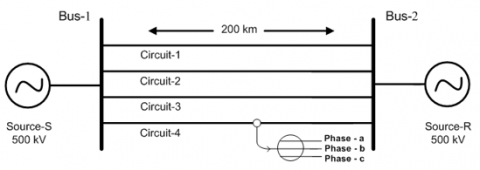
The transmission line is a FCPTL, 500kV with a length of 200km at a frequency of 50Hz. A schematic illustration for the FCPTL is depicted in Figure 1. The distributed parameter design is used by considering all the details. The FCPTL tower configuration is obtained from the existing design of the MATLAB library. The FCPTL details are given in Table 1. Three-phase fault breaker component is taken in circuit-1, circuit-2, circuit-3 and circuit-4 to simulate inter circuit faults with varying fault parameters. Fault which occurs in different phases of different circuits on same location at once are called as inter circuit fault. In such case, the location of faults is considered on same location at the same time but in different circuits. The presence of the inter circuit in a fault loop influences the steady and transient state component in the currents. The inter circuit fault create serious power system damages and may lead to malfunction of the relays. The possible number of inter circuit faults in FCPTL are 1368.
Figure 1. Schematic illustration for the FCPTL
Table 1. Details of FCPTL
|
Parameter |
Nominal Values |
|
Number of Circuits |
4 |
|
Number of Phases |
3 |
|
Line Length |
200km |
|
Frequency |
50Hz |
|
Nominal Source Voltage |
500kV |
|
Zero sequence of Bus-1 |
2.8 + 32.4i |
|
Positive sequence of Bus-1 |
1.6 + 18.5i |
|
Negative sequence of Bus-1 |
1.6 + 18.5i |
|
Zero sequence of Bus-2 |
2.1 + 24.5i |
|
Positive sequence of Bus-2 |
1.2 + 13.8i |
|
Negative sequence of Bus-2 |
1.2 + 13.8i |
Figure 2. Process of inter circuit fault location detection method based on fuzzy
The normal condition is represented with a certain value of current in any electrical system. When fault happen in the system, currents will be deviate from the normal situation. This current can be used to distinguish fault and normal situations. As the one phase fault is in circuit-2, thus the same phase currents increase significantly; nevertheless, the current of corresponding same phase of circuit-1, circuit-3 and circuit-4 also gets affected owing to the mutual coupling effects in FCPTL. Thus, the currents are used only to locate inter circuit faults in this work. To accomplish this work, currents of various fault conditions are analyzed, extensively changing parameters. These are simulated on FCPTL which include the changes in (i) inter circuit faults (ii) inception angle (iii) fault resistance and (iv) fault location. All the simulations are carried out on an Intel core i3-2.10 GHz processor with 4 GB of RAM with MATLAB 2014a software.
Inter circuit faults may occur on long FCPTL and should be identified and located precisely. To solve this problem, the recorded instantaneous three phase currents of circuit-1, circuit-2, circuit-3 and circuit-4 are applied to a 2nd order Butterworth low pass filter (BW-LPF). The BW-LPF cut-off frequency is 480 Hz. Further, these currents are sampled with sampling frequency of 1.2 kHz. This sampling frequency has been considered based on the Nyquist criteria. After that, magnitudes are given to one full cycle of discrete Fourier transform (DFT) for estimation of the fundamental current magnitudes. Now, these currents are normalized in between -1 to +1. The aforesaid procedure is carried out to attain the features for FCC of each circuit. The inputs to the proposed method are mainly the normalized FCC magnitudes recorded at relay end of FCPTL. The outline of proposed system for inter circuit fault location estimation and obtaining of FCC is depicted in Figure 2. The building of FES is described the next section.
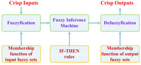
Figure 3. The process of fuzzy expert system
In this section, the development of a FES approach-based protection system including inter circuit faults in FCPTL has been illustrated. As discussed earlier, the implementation of FES is motivated by its ability to handle complex data with less computation burden. Fuzzy inference is defined as the process of mapping input data set into output data set, using a fuzzy logic concept and falls into the type of box model. Figure 3 gives the process of fuzzy expert system. Decision can be done on basis of patterns discerned or mapping. First, the fuzzification phase consists of collecting crisp sets of input data and transforming it into fuzzy sets by membership function (MSF), fuzzy linguistic terms and variables. Subsequently, an expert is evaluated according to a set of If-Then fuzzy rules. Lastly, the defuzzification phase makes it possible to convert the resulting fuzzy output into a crisp output by the MSF. The FES has been successfully applied in several fields viz. system identification, automatic control, fault diagnosis, data classification, computer vision and decision analysis.
The FES can be design more effective if perform certain processing steps on the system inputs and outputs. FES has many degrees of freedom, namely, the fuzzy logic operations used, the underlying fuzzy partition of the input-output spaces, the fuzzification-defuzzification phases employed, etc. As it can be observed, FES approach is tasked for locating inter circuit faults in FCPTL. The decision systems are constructed based on the toolbox of fuzzy logic in LabVIEW. It is the tool of option owing to its unparalleled connection of instruments, dominant data acquisition capability, scalability, overall function completeness and natural dataflow for graphical programming interface. The currents are studied broadly to develop the FES so that it can obtain maximum accuracy. The parameter that is FCC of each phase of FCPTL is considered as FES each input whereas the output of FES is denoted as location. The FES approach has executed with fault current data set based on Mamdani type. Such a method can get into account the nonlinear interactions that can be present between IF-Then rules-based system and features.
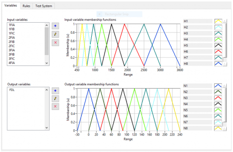
Figure 4. The MSF of FES
Table 2. Input-Output fuzzy sets for FES
|
System |
System Variables |
Linguistic Variables |
MSF Type |
MSF Names |
|
FES |
Inputs (12) |
1FIA, 1FIB, 1FIC, 2FIA, 2FIB,2FIC, 3FIA, 3FIB, 3FIC, 4FIA, 4FIB, 4FIC |
Triangular |
H1, H2, H3, H4, H5, H6, H7 and H8 |
|
Output (1) |
Fault Distance Location (FDL) |
Triangular |
N1, N2, N3, N4, N5, N6, N7 and N8 |
Before decision process, structure of the FES consists of 12 inputs, 8 rules and 1 output. The inputs fuzzification is done with linguistics H1, H2.....H7 and H8 to express the features depending on the universe of discourse levels. Eight groups of customized triangular shaped N1, N2…. N7 and N8 are then labeled for all output features and represent how features are mapping to a membership area with a degree between 0 and 1. Most important component of the fuzzy logic is developing the rule base for various systems. The rule base illustrates the reasoning relationship between output fuzzy sets and input fuzzified feature space by If-Then expressions. The MSF of FES is illustrated in Figure 4. The linguistic variables, MSF type and MSF names in each input-output of FES are demonstrated in Table 2. Then, the aggregation value is converted into a crisp values for faults by centroid defuzzification. The proposed FES systems can give precise results by interring the suitable input parameters after completion of modeling. Furthermore, the FES model is active all the time. The following rules have been framed for FES.
IF-THEN RULES
Rule1: IF (1FIA is H1) or (1FIB is H1) or (1FIC is H1) or (2FIA is H1) or (2FIB is H1) or (2FIC is H1) or (3FIA is H1) or (3FIB is H1) or (3FIC is H1) or (4FIA is H1) or (4FIB is H1) or (4FIC is H1) THEN (FDL is N8)
Rule2: IF (1FIA is H2) or (1FIB is H2) or (1FIC is H2) or (2FIA is H2) or (2FIB is H2) or (2FIC is H2) or (3FIA is H2) or (3FIB is H2) or (3FIC is H2) or (4FIA is H2) or (4FIB is H2) or (4FIC is H2) THEN (FDL is N7)
Rule3: IF (1FIA is H3) or (1FIB is H3) or (1FIC is H3) or (2FIA is H3) or (2FIB is H3) or (2FIC is H3) or (3FIA is H3) or (3FIB is H3) or (3FIC is H3) or (4FIA is H3) or (4FIB is H3) or (4FIC is H3) THEN (FDL is N6)
Rule4: IF (1FIA is H4) or (1FIB is H4) or (1FIC is H4) or (2FIA is H4) or (2FIB is H4) or (2FIC is H4) or (3FIA is H4) or (3FIB is H4) or (3FIC is H4) or (4FIA is H4) or (4FIB is H4) or (4FIC is H4) THEN (FDL is N5)
Rule5: IF (1FIA is H5) or (1FIB is H5) or (1FIC is H5) or (2FIA is H5) or (2FIB is H5) or (2FIC is H5) or (3FIA is H5) or (3FIB is H5) or (3FIC is H5) or (4FIA is H5) or (4FIB is H5) or (4FIC is H5) THEN (FDL is N4)
Rule6: IF (1FIA is H6) or (1FIB is H6) or (1FIC is H6) or (2FIA is H6) or (2FIB is H6) or (2FIC is H6) or (3FIA is H6) or (3FIB is H6) or (3FIC is H6) or (4FIA is H6) or (4FIB is H6) or (4FIC is H6) THEN (FDL is N3)
Rule7: IF (1FIA is H7) or (1FIB is H7) or (1FIC is H7) or (2FIA is H7) or (2FIB is H7) or (2FIC is H7) or (3FIA is H7) or (3FIB is H7) or (3FIC is H7) or (4FIA is H7) or (4FIB is H7) or (4FIC is H7) THEN (FDL is N2)
Rule8: IF (1FIA is H8) or (1FIB is H8) or (1FIC is H8) or (2FIA is H8) or (2FIB is H8) or (2FIC is H8) or (3FIA is H8) or (3FIB is H8) or (3FIC is H8) or (4FIA is H8) or (4FIB is H8) or (4FIC is H8) THEN (FDL is N1)
The effectiveness of the optimized FES based protection system has been evaluated in this section. To investigate this study, inter circuit faults are simulated on the 200km, 500kV, FCPTL. Numerous simulation studies have been conducted with different inter circuit fault cases. There are total of 20000 patterns obtained for testing data. The fault study is performed on the fuzzy test systems using LabVIEW software. The test results for various inter circuit faults are listed in Tables 3-7. Location of maximum absolute error (MAE) is measured by Eq. (1). The performance of proposed FES systems is evaluated for different fault types, fault resistances, faults inception angles, and fault locations, which are explained in detail below.
$\operatorname{MAE}(\%)=\frac{|\mathrm{A}-\mathrm{E}|}{\mathrm{L}} \times 100$ (1)
A- Actually fault location;
E- Estimate fault location;
L- Line length.
Table 3. Response of FES for varying inter circuit fault types
|
Actually fault location (km) |
Resistance (Ω) |
Type of fault |
Inception angle (°) |
Estimated fault location (km) |
MAE (%) |
|
93 |
45 |
C1-C2 |
300 |
93.042 |
0.021 |
|
93 |
45 |
A2-C3-A4 |
300 |
92.920 |
0.040 |
|
93 |
45 |
B1-A2-B3-A4 |
300 |
93.466 |
0.233 |
|
93 |
45 |
A1C1-B2-C3-C4 |
300 |
92.854 |
0.073 |
|
93 |
45 |
A1C1-B2C2-C3-C4 |
300 |
92.946 |
0.027 |
|
93 |
45 |
A1B1-B2C2-C3-A4C4 |
300 |
93.424 |
0.212 |
|
93 |
45 |
A1C1-A2C2-A3C3-A4C4 |
300 |
93.245 |
0.123 |
|
93 |
45 |
A1B1-A2B2C2-A3B3C3-A4C4 |
300 |
93.190 |
0.095 |
|
93 |
45 |
A1B1C1-A2B2-A3B3C3-A4B4C4 |
300 |
93.123 |
0.062 |
|
93 |
45 |
A1B1C1-C2-A3-A4 |
300 |
93.292 |
0.146 |
|
93 |
45 |
A1B1C1-B2C2-C3-B4 |
300 |
93.053 |
0.027 |
|
93 |
45 |
A1B1-A2C3-A3B3C3-A4 |
300 |
93.118 |
0.059 |
|
93 |
45 |
A1C1-B2C2-B3C3-A4B4C4 |
300 |
93.244 |
0.122 |
|
93 |
45 |
A1B1-A2B2C2-B3C3-A4B4C4 |
300 |
93.009 |
0.005 |
|
93 |
45 |
A1B1C1-A2B2C2-A3B3C3-A4C4 |
300 |
93.390 |
0.195 |
|
93 |
45 |
A1B1C1-A2B2C2-A3B3C3-A4B4C4 |
300 |
93.103 |
0.052 |
Table 4. Response of FES for varying shunt faults
|
Actually fault location (km) |
Resistance (Ω) |
Type of fault |
Inception angle (°) |
Estimated fault location (km) |
MAE (%) |
|
98 |
5 |
A1B1 |
0 |
98.043 |
0.022 |
|
48 |
15 |
A2B2 |
60 |
47.780 |
0.110 |
|
28 |
25 |
A3B3 |
120 |
28.099 |
0.050 |
|
68 |
35 |
A4B4 |
180 |
67.869 |
0.066 |
|
29 |
45 |
B1C1 |
240 |
29.085 |
0.043 |
|
40 |
55 |
B2C2 |
300 |
40.122 |
0.061 |
|
19 |
65 |
B3C3 |
360 |
19.150 |
0.075 |
|
09 |
75 |
B4C4 |
0 |
09.900 |
0.050 |
|
65 |
5 |
C1A1 |
0 |
65.286 |
0.143 |
|
86 |
15 |
C2A2 |
60 |
86.364 |
0.182 |
|
74 |
25 |
C3A3 |
120 |
74.077 |
0.039 |
|
47 |
75 |
C4A4 |
60 |
47.050 |
0.025 |
|
38 |
35 |
A1B1C1 |
180 |
38.038 |
0.019 |
|
66 |
45 |
A2B2C2 |
240 |
66.366 |
0.183 |
|
08 |
55 |
A3B3C3 |
300 |
07.908 |
0.046 |
|
46 |
65 |
A4B4C4 |
360 |
46.090 |
0.045 |
Table 5. Response of FES for varying inception angles
|
Actually fault location (km) |
Resistance (Ω) |
Type of fault |
Inception angle (°) |
Estimated fault location (km) |
MAE (%) |
|
16 |
60 |
A1-B2-A3-C4 |
0 |
16.042 |
0.021 |
|
16 |
60 |
A1-B2-A3-C4 |
60 |
15.912 |
0.044 |
|
16 |
60 |
A1-B2-A3-C4 |
120 |
16.236 |
0.118 |
|
16 |
60 |
A1-B2-A3-C4 |
180 |
16.052 |
0.026 |
|
16 |
60 |
A1-B2-A3-C4 |
240 |
16.194 |
0.097 |
|
16 |
60 |
A1-B2-A3-C4 |
300 |
15.834 |
0.083 |
|
16 |
60 |
A1-B2-A3-C4 |
360 |
16.128 |
0.064 |
|
16 |
60 |
A1-B2-A3-C4 |
30 |
16.364 |
0.182 |
|
16 |
60 |
A1-B2-A3-C4 |
90 |
15.760 |
0.120 |
|
16 |
60 |
A1-B2-A3-C4 |
150 |
16.428 |
0.214 |
|
16 |
60 |
A1-B2-A3-C4 |
210 |
16.048 |
0.024 |
|
16 |
60 |
A1-B2-A3-C4 |
270 |
16.094 |
0.047 |
|
16 |
60 |
A1-B2-A3-C4 |
330 |
15.749 |
0.126 |
|
16 |
60 |
A1-B2-A3-C4 |
315 |
15.842 |
0.079 |
|
16 |
60 |
A1-B2-A3-C4 |
75 |
15.840 |
0.080 |
|
16 |
60 |
A1-B2-A3-C4 |
225 |
15.898 |
0.051 |
Table 6. Response of FES for varying fault resistances
|
Actually fault location (km) |
Resistance (Ω) |
Type of fault |
Inception angle (°) |
Estimated fault location (km) |
MAE (%) |
|
158 |
5 |
A2-B4-G |
240 |
158.128 |
0.064 |
|
158 |
15 |
A2-B4-G |
240 |
157.928 |
0.036 |
|
158 |
25 |
A2-B4-G |
240 |
158.113 |
0.057 |
|
158 |
35 |
A2-B4-G |
240 |
158.023 |
0.012 |
|
158 |
45 |
A2-B4-G |
240 |
157.975 |
0.013 |
|
158 |
55 |
A2-B4-G |
240 |
158.147 |
0.074 |
|
158 |
65 |
A2-B4-G |
240 |
157.990 |
0.005 |
|
158 |
75 |
A2-B4-G |
240 |
158.313 |
0.157 |
|
158 |
5 |
A2-B4-G |
240 |
156.303 |
0.152 |
|
158 |
15 |
A2-B4-G |
240 |
158.225 |
0.113 |
|
158 |
25 |
A2-B4-G |
240 |
157.924 |
0.038 |
|
158 |
35 |
A2-B4-G |
240 |
157.868 |
0.066 |
|
158 |
45 |
A2-B4-G |
240 |
158.210 |
0.105 |
|
158 |
55 |
A2-B4-G |
240 |
158.333 |
0.167 |
|
158 |
65 |
A2-B4-G |
240 |
158.452 |
0.226 |
|
158 |
75 |
A2-B4-G |
240 |
158.254 |
0.127 |
4.1 Response of FES for varying inter circuit fault types
The FES is examined for various inter circuit fault types in FCPTL with C1-C2, A2-C3-A4, B1-A2-B3-A4, A1C1-B2-C3-C4, A1C1-B2C2-C3-C4, A1B1-B2C2-C3-A4C4, A1C1-A2C2-A3C3-A4C4, A1B1C1-C2-A3-A4, A1B1C1-B2C2-C3-B4, A1B1-A2C3-A3B3C3-A4, A1C1-B2C2-B3C3-A4B4C4, A1B1-A2B2C2-B3C3-A4B4C4, A1B1C1-A2B2C2-A3B3C3-A4C4, A1B1C1-A2B2C2-A3B3C3-A4B4C4 and results of MAE are illustrated in Table 3. The proposed FES has been evaluated for around 4000 fault type simulation cases. According to the test case results, it gives MAE within 0.233%. Therefore, it can be observed that FES can locate the inter circuit faults in FCPTL correctly and no effect for fault types.
4.2 Response of FES for varying shunt faults
The experimental results are also obtained to further check the performance of the FES approach for shunt faults. Further, Table 4 list down the shunt faults location under various location long the FCPTL. The proposed FES has been tested for approximately 4000 shunt fault cases. The MAE recorded is 0.183%. It can operate even with all fault parameter effects up to 366 m. From the results, it can be observed that FES approach has the ability in detecting shunt faults in FCPTL all fault parameter effects.
4.3 Response of FES for varying inception angles
The FES is verified for different fault inception angles of inter circuit fault in FCPTL with 0°, 60°, 120°, 180°, 240°, 300° and 360° and the MAE calculations are listed in Table 5. Total 4000 fault cases for different inception angles tested and FES based MAE is maximum of 0.214%. Therefore, one can understood that FES can cope with the inter circuit fault location and variation in inception angle changes have no significant effect in the MAE of the approach.
4.4 Response of FES for varying fault resistances
The FES is checked for various resistances of inter circuit fault in FCPTL with 5Ω, 15Ω, 25Ω, 35Ω, 45Ω, 55Ω and 65Ω and performance results are presented in Table 6. The total number of fault resistance cases simulated for checking the approach is 4000. The error is up to 0.226% for all types of fault resistances. Simulation results show the robustness of method against different fault resistances.
4.5 Response of FES for varying locations
The FES is tested for various locations of inter circuit fault in FCPTL with 4 km, 18 km, 29 km, 36 km, 68 km, 87 km, 98 km, 123 km, 131 km, 146 km 159 km, 168 km, 187 km and 195 km and some of test results are given in Table 7. The proposed FES has been tested for approximately 4000 fault location simulation cases. The MAE in different inter circuit fault locations is below 0.221%. It is noted clearly that FES is identified in the inter circuit fault location accurate and variation of fault locations have a negative impact on the MAE of the FES.
Table 7. Response of FES for varying fault locations
|
Actually fault location (km) |
Resistance (Ω) |
Type of fault |
Inception angle (°) |
Estimated fault location (km) |
MAE (%) |
|
4 |
50 |
B1C1-B3-A4B4C4 |
180 |
03.825 |
0.088 |
|
18 |
50 |
B1C1-B3-A4B4C4 |
180 |
18.253 |
0.127 |
|
29 |
50 |
B1C1-B3-A4B4C4 |
180 |
29.210 |
0.105 |
|
36 |
50 |
B1C1-B3-A4B4C4 |
180 |
36.116 |
0.058 |
|
68 |
50 |
B1C1-B3-A4B4C4 |
180 |
68.072 |
0.036 |
|
87 |
50 |
B1C1-B3-A4B4C4 |
180 |
86.904 |
0.048 |
|
98 |
50 |
B1C1-B3-A4B4C4 |
180 |
97.876 |
0.062 |
|
123 |
50 |
B1C1-B3-A4B4C4 |
180 |
123.360 |
0.180 |
|
131 |
50 |
B1C1-B3-A4B4C4 |
180 |
131.276 |
0.138 |
|
146 |
50 |
B1C1-B3-A4B4C4 |
180 |
146.234 |
0.117 |
|
159 |
50 |
B1C1-B3-A4B4C4 |
180 |
159.441 |
0.221 |
|
168 |
50 |
B1C1-B3-A4B4C4 |
180 |
168.348 |
0.174 |
|
187 |
50 |
B1C1-B3-A4B4C4 |
180 |
187.252 |
0.126 |
|
195 |
50 |
B1C1-B3-A4B4C4 |
180 |
195.133 |
0.067 |
|
196 |
50 |
B1C1-B3-A4B4C4 |
180 |
196.232 |
0.116 |
|
198 |
50 |
B1C1-B3-A4B4C4 |
180 |
198.193 |
0.087 |
Table 8. Comparisons between the existing approaches and developed method
|
Ref |
[26] |
[21] |
[8] |
[5] |
[30] |
[22] |
Proposed technique |
|
MAE% |
5 |
1.6 |
2.82 |
1.89 |
0.32 |
0.34 |
0.233 |
|
Approach used |
FES |
ANN |
Mathematical model |
ANFIS |
FES |
FES |
FES |
|
Type of input data |
Voltage and currents |
Voltage and currents |
Voltages and currents |
Currents |
Currents |
Currents |
Sending end currents |
|
Type of fault |
Shunt, series and simultaneous faults |
Cross country and inter circuit faults |
Shunt faults |
Shunt faults |
Shunt faults |
Multi location and transforming phase to ground faults |
Inter circuit faults |
|
Detection time |
- |
One cycle time |
One cycle time |
- |
One cycle time |
One cycle time |
1/2 cycle time |
4.6 Comparative assessment
To make the study more convincing, the comparison study has carried out with MAE in fault location, approach used, type of input data, type of fault and detection time. Comparisons between the existing methods and developed approach are given in Table 8 for the FCPTL. Most of the methods provided in Table 8 have MAE greater than 1% [5, 8, 21, 26] in fault location while developed method has up to 0.233% of line length. Moreover, previous paper has addressed ANN [21] scheme which was complex to design but the developed method designed without hidden layers, mean square error goal, number of neurons and activation functions and complexity. The inputs required for the fuzzy network [26] are only currents and voltages while the developed method requires currents. The techniques were located for only shunt faults [5, 8, 30] whereas the developed method locating the inter circuit and shunt faults also. Past works have published articles [8, 21, 22, 30] in which the detection time of faults was after 1 cycle, whereas the developed method detected 1/2 cycle time for all fault cases. Most of the existing methods in FCPTL [5, 21, 26] are depending on fault classification. The developed method is independent of fault classification and providing the precise fault location in FCPTL. The proposed technique overcomes problems such as information from two ends of the transmission line that was being addressed in the location of FCPTL. This approach is satisfactory when compared to approaches already used. Moreover, the proposed approach yields acceptable performance against MAE fault location line parameters. Based on the experiment results, it is observed that the proposed approach is more accurate than other fault protection methods. However, developed method performed relatively better.
The complexity arising due to inter circuit faults, which harmfully influence the performance of FCPTL relaying. Thus, this paper has outlined a new fault location scheme for FCPTL including inter circuit faults using fuzzy expert system. Further, the suggested approach uses one end data and gives satisfactory performance also. The suggested FES based relay is verified for all types of inter circuit faults with the different fault parameters. Accuracy of the proposed technique is 0.233% for location error of fault from all the studied fault cases. As a result it can be designed for protection of real system network as well. Experimentation on such application example lead to conclusions that FES approach gives a very simple and very straightforward way to frame fuzzy rules based system for a large number of problems. The proposed system overcomes problems viz. knowing the fault circuit, knowing the line information, synchronizing received information from two sides of FCPTL. Future work includes the consideration of theoretical and experimental study will be investigated thoroughly to design the proposed FES approach.
[1] Yalcin, M.A., Turan, M., Demir, Z. (1999). Effects of transmission line faults on dynamic voltage stability, powertech budapest 99. Abstract Records (Cat. No. 99EX376), Budapest, Hungary.
[2] Ismail, H.M. (2002). Magnetic field of high-phase order and compact transmission lines. International Journal of Energy Research, 26(1): 45-55. https://doi.org/10.1002/er.762
[3] Fan, C., Liu, L., Tian, Y. (2010). A fault-location method for 12-phase transmission lines based on twelve-sequence-component method. IEEE Transactions on Power Delivery, 26(1): 135-142. https://doi.org/10.1109/TPWRD.2010.2079337
[4] Pal, U., Singh, L.P. (1985). Feasibility and fault analysis of multi-phase (12-phase) systems. Journal of the Institution of Engineers. India. Electrical Engineering Division, 65(4): 138-146.
[5] Khaleghi, A., Oukati Sadegh, M. (2019). Single-phase fault location in four-circuit transmission lines based on wavelet analysis using ANFIS. Journal of Electrical Engineering & Technology, 14(4): 1577-1584. https://doi.org/10.1007/s42835-019-00209-7
[6] Gajare, S., Pradhan, A.K. (2016). An accurate fault location method for multi-circuit series compensated transmission lines. IEEE Transactions on Power systems, 32(1): 572-580. https://doi.org/10.1109/TPWRS.2016.2562125
[7] Ngu, E.E., Ramar, K., Eisa, A. (2012). One-end fault location method for untransposed four-circuit transmission lines. International Journal of Electrical Power & Energy Systems, 43(1): 660-669. https://doi.org/10.1016/j.ijepes.2012.06.033
[8] Saber, A. (2018). New fault location scheme for four-circuit untransposed transmission lines. International Journal of Electrical Power & Energy Systems, 99: 225-232. https://doi.org/10.1016/j.ijepes.2018.01.006
[9] Saber, A. (2020). New fault location algorithm for four-circuit overhead lines using unsynchronized current measurements. International Journal of Electrical Power & Energy Systems, 120: 106037. https://doi.org/10.1016/j.ijepes.2020.106037
[10] McDaniel, R. (2015). Analysis of a relay Operation for an Intercircuit fault. In 2015 68th Annual Conference for Protective Relay Engineers, pp. 462-477. https://doi.org/10.1109/CPRE.2015.7102185
[11] Hodge, E., Atienza, E. (2016). Line protection response to a three-phase intercircuit fault. In 2016 69th Annual Conference for Protective Relay Engineers (CPRE), pp. 1-6. https://doi.org/10.1109/CPRE.2016.7914893
[12] Corpuz, G., Young, J., Authority, L.C.R. (2014). Case study: analysis of a 138 kV intercircuit fault. In 41st Annu. Western Protective Relay Conf, pp. 1-17.
[13] Saha, M.M., Smetek, G., Izykowski, J., Rosolowski, E., Pierz, P. (2015). Location of inter-circuit faults on double-circuit transmission line. In 2015 Modern Electric Power Systems (MEPS), pp. 1-7. https://doi.org/10.1109/MEPS.2015.7477199
[14] Makwana, V.H., Bhalja, B. (2011). New adaptive digital distance relaying scheme for double infeed parallel transmission line during inter-circuit faults. IET Generation, Transmission & Distribution, 5(6): 667-673.
[15] Makwana, V.H., Bhalja, B.R. (2016). Digital distance relaying scheme for parallel transmission lines during inter-circuit faults. In Transmission Line Protection Using Digital Technology, 65-88. https://doi.org/10.1007/978-981-10-1572-4_4
[16] Hasheminejad, S., Seifossadat, S.G., Joorabian, M. (2017). New travelling-wave-based protection algorithm for parallel transmission lines during inter-circuit faults. IET Generation, Transmission & Distribution, 11(16): 3984-3991.
[17] Swetapadma, A., Yadav, A. (2016). Directional relaying using support vector machine for double circuit transmission lines including cross-country and inter-circuit faults. International Journal of Electrical Power & Energy Systems, 81: 254-264. https://doi.org/10.1016/j.ijepes.2016.02.034
[18] Swetapadma, A., Yadav, A. (2016). Protection of parallel transmission lines including inter-circuit faults using Naïve Bayes classifier. Alexandria Engineering Journal, 55(2): 1411-1419. https://doi.org/10.1016/j.aej.2016.03.029
[19] Spoor, D.J., Zhu, J. (2005). Intercircuit faults and distance relaying of dual-circuit lines. IEEE Transactions on Power Delivery, 20(3): 1846-1852. https://doi.org/10.1109/TPWRD.2004.833899
[20] Bachmatiuk, A., Izykowski, J. (2013). Distance protection performance under inter-circuit faults on double-circuit transmission line. Przeglad Elektrotechniczny, 89(1): 7-11.
[21] Jain, A., Thoke, A.S., Patel, R.N., Koley, E. (2010). Intercircuit and cross-country fault detection and classification using artificial neural network. In 2010 annual IEEE India Conference (INDICON), pp. 1-4. https://doi.org/10.1109/INDCON.2010.5712601
[22] Kumar, A.N., Chakravarthy, M. (2018). Fuzzy inference system based distance estimation approach for multi location and transforming phase to ground faults in six phase transmission line. International Journal of Computational Intelligence Systems, 11(1): 757-769.
[23] Kumar, A.N., Ramesha, M., Jagadha, S., Gururaj, B., Kumar, M.S., Chaitanya, K. (2021). Fuzzy rule-based fault location technique for thyristor-controlled series-compensated transmission lines. International Journal of Fuzzy Logic and Intelligent Systems, 21(4): 391-400. https://doi.org/10.5391/IJFIS.2021.21.4.391
[24] Kumar, A.N., Sanjay, C., Chakravarthy, M. (2020). Mamdani fuzzy expert system based directional relaying approach for six-phase transmission line. Int. J. Interact. Multim. Artif. Intell., 6(1): 41-50. https://doi.org/10.9781/ijimai.2019.06.002
[25] Swetapadma, A., Yadav, A. (2016). Fuzzy based fault location estimation during unearthed open conductor faults in double circuit transmission line. In Information Systems Design and Intelligent Applications, 445-456. https://doi.org/10.1007/978-81-322-2752-6_44
[26] Swetapadma, A., Yadav, A. (2015). Fuzzy inference system approach for locating series, shunt, and simultaneous series-shunt faults in double circuit transmission lines. Computational Intelligence and Neuroscience, 2015: 79. https://doi.org/10.1155/2015/620360
[27] Kumar, A.N., Sanjay, C., Chakravarthy, M. (2019). Six phase transmission line protection against open conductor, phase to ground and simultaneous faults using fuzzy inference system. International Journal of Computational Intelligence Studies, 8(3): 245-267.
[28] Mishra, P.K., Yadav, A. (2018). A single ended fuzzy based directional relaying scheme for transmission line compensated by fixed series capacitor. In International Conference on Intelligent Systems Design and Applications, pp. 749-759. https://doi.org/10.1007/978-3-030-16660-1_73
[29] Mishra, P.K., Yadav, A. (2019). Combined DFT and fuzzy based faulty phase selection and classification in a series compensated transmission line. Modelling and Simulation in Engineering, 2019: Article ID 3467050. https://doi.org/10.1155/2019/3467050
[30] Nawfal Abd Alrazaaq, S., Hamid Ali, F. (2009). Fuzzy self tuning of DC position control based on LabVIEW. Al-Rafidain Engineering Journal (AREJ), 17(4): 73-83. https://doi.org/10.33899/rengj.2009.43288
[31] Jin, M.L., Ho, M.C. (2009). Labview-based fuzzy controller design of a lighting control system. System, 17(2): 5. https://doi.org/10.51400/2709-6998.1965
[32] Kumar, A.N., Sanjay, C., Chakravarthy, M. (2020). A single-end directional relaying scheme for double-circuit transmission line using fuzzy expert system. Complex & Intelligent Systems, 6(2): 335-346. https://doi.org/10.1007/s40747-020-00131-w