Tsutomu Sekine* | Kyoko Kameya
© 2021 IIETA. This article is published by IIETA and is licensed under the CC BY 4.0 license (http://creativecommons.org/licenses/by/4.0/).
OPEN ACCESS
This study describes remarkable characteristics of a novel path interval determination in filleted end milling with a tool inclination. CNC milling machine is one of the core technologies in practical manufacturing. Computer-aided technologies have contributed to the technological advancement. Tool path generation in computer-aided manufacturing is really important for CNC milling process. Although there are a lot of parameters treated in tool path generation, path interval is one of the influential factors in considering the balance between manufacturing efficiency and machined surface feature. A path interval determination in filleted end milling commonly entails the intersection problems with mathematical complexities in essence. The related studies have been reported so far, while there has scarcely been a procedure to cope effectively with the complexities. Hence, this study focused on a novel path interval determination proposed in our previous study. After the analytical discussions were made with the computational and experimental results, it was acquired from the explicit evidences that the novel procedure possessed remarkable characteristics contributable for a path interval determination in multi-axis filleted end milling.
tool path generation, path interval, multi-axis CNC machining, filleted end mill, experimental verification
Smart manufacturing recently begun to attract much attention in industrial society [1, 2]. To create the next-generation, intelligent system, the manufacturing technologies based on the real-time data have been made continuously in various fields. This practical applicability is rapidly increasing with the development of data-driven technologies such as artificial intelligence and machine learning [3]. Accordingly, the growing interest is being acquired from a lot of researchers in various fields associated with the technologies [4].
The fourth industrial revolution, so-called Industry 4.0, is a well-known concept and direct trigger in the development of smart manufacturing [5]. The concept was created based on the recent advances of information and communication technologies. Moreover, the similar concepts, such as “Industrial Internet of Things,” have been made one after another. Even in the field of machine tools, Machine tool 4.0 was proposed as a derivative concept including internet of things and cloud computing applied to computer numerically controlled (CNC) machine tools [6], while each mechanical element with high performance was indispensable to collect high-precision data. This suggests that the improvement of each mechanical element has a valuable potential to enhance the performance of technologies related to smart manufacturing.
CNC machine tools are widely used in today’s industry [7-9]. Although smart manufacturing based on real-time sensor data is expected to inspire further innovation in production system, its maximum benefit would be unobtainable without product manufacturing controlled adaptively in the optimum condition. Milling with CNC machine tools is one of the core technologies in manufacturing processes. Computer-aided technologies have contributed to the technological advancement. It is unquestionable that computer-aided design (CAD) plays an important role in creative process of various products [10]. Product manufacturing with CNC machine tools is practically conducted based on a designed shape constructed in CAD, and the process planning is arranged using computer-aided manufacturing (CAM) [11, 12]. The machine movement produced by CAM has great influence on surface quality, machining efficiency, etc. in practical milling process, so that tool path generation has been studied for the further advancement of milling [13-15]. However, there still exist the further demands awaited highly such as higher machining speeds and longer tool life.
Path interval is one of the influential factors in considering the balance between manufacturing efficiency and machined surface feature, while there are a lot of setting parameters in tool path generation. Two path intervals have been investigated to improve the balance in milling [16, 17]. Those are a path interval along both the feed direction of a tool and the cross-feed direction of a tool. Path interval determination have mostly focused on the latter [18, 19]. In the related studies, scallop height acts as a controllable factor to predict a proper path interval. Here, there are various kinds of tools for milling in these days. Among them, typical tool tip geometries have been mainly investigated in path interval determination. For instance, the tool tip geometry in ball end milling can be considered as a half circle in case that the tool having contact at a point on a designed shape is projected onto an instantaneous section defined according to both tool path and tool posture [20, 21]. The intersection problem regarding path interval determination is expressed using a designed shape and two half circles obtained from adjacent tool paths. The geometrical consideration can derive a path interval formula, and the solution enables us to provide a suitable path interval or scallop height in ball end milling [22, 23].
Different viewpoints are inevitably required in multi-axis flat and filleted end milling. Advanced treatment is necessary in the geometrical modelling because of the typical cutting-edge geometries. These profiles projected onto an instantaneous section change circumstantially with a variation of both tool path and tool posture [24-26]. The procedures with wide applicability, robustness, efficiency, and accuracy were reported to determine a proper path interval in multi-axis flat end milling [27].
On the other hand, it was clarified that the machining situations in multi-axis filleted end milling could be classified into four general groups [28]. In addition, grabbing the geometrical relationships was extremely difficult with the two-dimensional expression for the cutting edge geometry. Segonds et al. [29] reported comparative results between theoretical and experimental studies in filleted end milling, while the results were inexplicably limited to a certain small range of step over distance. In three-dimensional (3D) expression, it was reported that mathematical complexities arose according to intersection problems of 3D geometries [30]. A novel procedure focusing on a reference point was studied to enhance predictiveness of path interval determination in filleted end milling with a tool inclination [31]. The findings indicated that introducing the reference point was important to estimate a path interval correctly in the 3D consideration. However, only a few was represented regarding the path interval and scallop height, and these characteristics were unclear for practical application.
The aim of this study is to investigate the practical characteristics of novel procedure through the proper experiments of filleted end milling with a tool inclination. A computational algorithm for path interval determination was explained with reference to the literature [31]. Then, the experimental verification was represented according to the results measured using an optical microscope. After that, some conclusions were drawn to acquire a suitable path interval in multi-axis filleted end milling.
This section provides a novel procedure to obtain a suitable path interval in filleted end milling. Figure 1 shows the pseudo-code of novel procedure proposed in our previous study. The algorithm supposes that filleted end milling with a tool inclination along a tool feed direction is performed on a plane to obtain a designed surface topography. A path interval commonly expresses a distance between adjacent tool paths, while L / 2 is defined hereafter as a path interval, which is a unilateral distance from a tool center point to the section with predetermined scallop height h. Figure 2 shows several radii, i.e. R, Rb, and Rcr, of filleted end mill with a tool inclination along a tool feed direction. The figure also includes a tool inclination angle ρ. A torus is used to express geometrical features in the cutting edge geometry of filleted end mill.
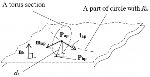
A machining situation of cutting edge geometry is given in Figure 3. X, Y, and Z are each axis of global coordinate system. The components of each axis are set as (1, 0, 0), (0, 1, 0), and (0, 0, 1), respectively. In contrast, XT, YT, and ZT are each axis of tool coordinate system. The direction of YT axis is the same as that of Y axis, and tool feed direction coincides with the direction of X axis. For simple treatment of torus-related problems, we set two planes, i.e. a designed surface and h pseudo plane. The distance of two planes becomes h in any position. nh is a surface normal of h pseudo plane. Here, the torus with inclination ρ has contact with a designed surface. Then, assuming that a section as an exact circle is cut out from the torus, there exist three positional relationships between a torus section and h pseudo plane. The one is an intersection between a torus section and h pseudo plane, while there exists a positional relationship without an intersection. The other situation is a single contact point between a torus section and h pseudo plane.
Figure 1. Computational algorithm [31]
Figure 2. Several radii and a tool inclination angle p
Figure 3. Geometrical relationships between a torus (cutting edge geometry) and two planes
Figure 4. Geometrical relationships in some variables related to a torus section
The notation P means a positional vector in 3D space. The notation t also signifies a tangent vector at each torus section’s center. Moreover, the notation u indicates a directional vector. Each subscript of these vectors is mainly associated with the positional relationships between a torus section and h pseudo plane. The subscript base is used for Pbase and tbase which represent vectors at torus section’s center with a contact point between the torus and a designed shape. Moreover, the distance between Pbase and a designed shape is completely equal to Rcr. The subscript ap is used to express an arbitrary position. γ is an angular parameter for determining an arbitrary position on a circle with Rb. Rearranging the following formula can provide the initial value of designated as γap in Figure 1.
${{R}_{b}}\sin \rho -{{R}_{b}}\cos \gamma \sin \rho =0.5h$ (1)
A search range in iterative calculation is introduced along a circle with Rb. Pap is an arbitrary position on the circle. Pstart and Pend are temporarily provided as the starting and ending point of search range, respectively. Pstart is a position vector when γ = 0, while Pend is a position vector when γ = 0.5π. A position vector of Pap can be easily derived through rotating Pbase around ZT axis. Moreover, a tangent vector tap can be also calculated using tbase in the same manner. Figure 4 illustrates some variables in a torus section at Pap. Php indicates a positional vector on h pseudo plane. A direction cosine η between tap and h pseudo plane can be calculated from the following equation:
$\eta ={{\mathbf{t}}_{\mathbf{ap}}}\cdot \left\{ \left( {{\mathbf{n}}_{\mathbf{h}}}\times {{\mathbf{t}}_{\mathbf{ap}}} \right)\times {{\mathbf{n}}_{\mathbf{h}}} \right\}$ (2)
A distance ds between Pap and Php can be given as follows:
${{d}_{s}}=\frac{\left( {{R}_{cr}}-h+{{R}_{b}}\sin \rho -{{R}_{b}}\cos \gamma \sin \rho \right)}{\eta }$ (3)
The subscript scp means a single contact point between a torus section and h pseudo plane. Pscp and tscp are obtained through updating Pap and tap in iterative calculation, which is the first do-while statement in Figure 1. ε is set as the convergence condition of iterative calculation. The second iterative calculation in Figure 1 can ascertain an intersection between a torus section and h pseudo plane. Through finding out the farthest intersection from the tool center point, the algorithm can provide a suitable path interval L/2.
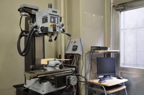
Experiments were conducted with CNC milling machine whose type was PSF550-CNC, as shown in Figure 5. The spindle of milling machine can be tilted with the available range from -30 to 90 deg. With the mechanism of tilting spindle, tool inclination angle ρ was properly adjusted in accordance with each experimental condition. Filleted end mills (2RBE) made by FUKUDA SEIKO Co. Ltd. were individually attached to the spindle, and each radius of tools was R = 3.0, 5.0, 6.0, and 7.0 mm, respectively. In addition, each radius of tool’s cutting edges was Rcr = 1.0, 1.0, 2.0, and 3.0 mm, respectively. A synthetic wood, SANMODUR MH-E, was used as a material to be machined. The material was attached to a vice on the machine’s table. Table 1 shows the experimental conditions. The conditions were cautiously determined based on the results of preliminary experiments.
Figure 5. An appearance of CNC milling machine (PSF550-CNC)
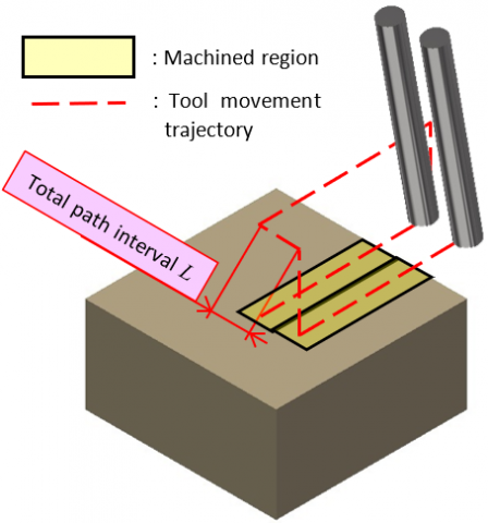
In each experiment, path interval L / 2 was numerically calculated under the two conditions of scallop height, i.e., h = 0.05 and 0.10 mm. For each experimental condition, total path interval L was given as the summation of adjacent path intervals L / 2. Figure 6 is an example of tool path prepared for each experiment. As illustrated in Figure 6, the scanning line machining was executed only from one direction in each experiment. The milling processes in each experimental condition were performed three times to investigate the repeatability of machined surface feature.
Table 1. Experimental conditions in each filleted end mill
|
Parameters |
Tool 1 |
Tool 2 |
Tool 3 |
Tool 4 |
|
Tool radius R [mm] |
3.0 |
5.0 |
6.0 |
7.0 |
|
Tool tip radius Rcr [mm] |
1.0 |
1.0 |
2.0 |
3.0 |
|
Depth of cut [mm] |
4.5 |
5.5 |
6.5 |
7.0 |
|
Tool rotational speed S [min-1] |
1400 |
1400 |
1200 |
1200 |
|
Feed rate F [mm/min] |
100 |
100 |
100 |
100 |
Figure 6. A schematic illustration of tool movement trajectory in each experimental condition
Figure 7. A machined material for making a cut-out specimen
After the experiments, a specimen was cut out from a machined material. The cut-out part can be identified as a hatched area in Figure 7; moreover, Figure 8 expresses one of the actual specimens. A configuration of measurement system is shown in Figure 9. Optical microscope (Mitutoyo TM-505) was used for the measurements after experiments. The cut-out specimen was set on the stage of microscope. Then, the scallop height was measured in each machined part. The average value was calculated after three measurements in each experimental condition. These values were compared with the computed ones obtained using the procedure explained above. In terms of practically-beneficial path interval determination in multi-axis filleted end milling, the suitability, applicability, and predictiveness were discussed based on the results.
Figure 8. A specimen for measurement of scallop height on a machined surface
Figure 9. A system configuration of optical microscope with a specimen
This section describes the remarkable features of novel procedure from several viewpoints. After the experimental verification of filleted end milling with a tool inclination, the several characteristics will be discussed with visual evidences. The findings can provide proper measures to the effective application of filleted end mills. Hereafter, degrees are used as units to express tool inclination angle ρ.
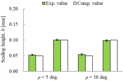
Figure 10 is graphic comparisons of the experimental and computed values when R = 3 mm and Rcr = 1 mm, while Figure 11 is graphic comparisons of the both values when R = 6 mm and Rcr = 2 mm. In addition, Tables 2 and 3 represent both path intervals L / 2 and absolute differences of compared scallop height |he - h| in each experimental condition corresponding to those in Figures 10 and 11. Here, he means an average value of scallop height observed in each measurement. It was obvious from Figure 10 that the novel procedure could estimate a suitable path interval with high accuracy even when tool inclination angle ρ changes according to a machining situation. Table 2 also demonstrated that |he - h| were extremely small. It should be kept in mind that the experimental results provided to comparisons include several errors occurred with the experiments. Even though there exist the other unaware factors possible to reduce cutting accuracy, those values would not have a serious negative effect on machined surface features from practical perspective. The similar results were also acquired under the experimental condition in Figure 11 and Table 3. From the results in two figures and tables, it was undoubted that the algorithm of novel procedure could properly cover an isotropic, uniform variation of tool tip geometry in multi-axis filleted end milling.
Table 2. The path intervals L / 2 and absolute differences of compared scallop height |he - h| under the condition that R = 3 mm and Rcr = 1 mm
|
Parameters |
Condition 1 |
Condition 2 |
Condition 3 |
Condition 4 |
|
r [deg.] |
5 |
10 |
||
|
h [mm] |
0.05 |
0.10 |
0.05 |
0.10 |
|
L / 2 [mm] |
1.442 |
1.879 |
1.083 |
1.479 |
|
|he - h| |
0.002 |
0.000 |
0.004 |
0.001 |
Table 3. The path intervals L / 2 and absolute differences of compared scallop height |he - h| under the condition that R = 6 mm and Rcr = 2 mm
|
Parameters |
Condition 1 |
Condition 2 |
Condition 3 |
Condition 4 |
|
r [deg.] |
5 |
10 |
||
|
h [mm] |
0.05 |
0.10 |
0.05 |
0.10 |
|
L / 2 [mm] |
2.115 |
2.883 |
1.558 |
2.167 |
|
|he - h| |
0.001 |
0.003 |
0.001 |
0.000 |
Figure 10. The graphic comparisons between experimental and computed results under the condition that R = 3 mm and Rcr = 1 mm
Figure 11. The graphic comparisons between experimental and computed results under the condition that R = 6 mm and Rcr = 2 mm
The next attention was drawn to some variations of path interval in Table 2 and 3. When R = 3 mm and ρ = 5 deg., each path interval was calculated as 1.442 and 1.879 mm for each scallop height which was 0.05 and 0.1 mm. When R = 3 mm and ρ = 10 deg. under the same scallop heights, each path interval was given as 1.083 and 1.479 mm, respectively. Likewise, when R = 6 mm and ρ = 5 deg., 2.115 and 2.883 mm were the computational values through the novel procedure. Moreover, when R = 6 mm and ρ = 10 deg., 1.558 and 2.167 mm were the results according to the pre-determined scallop heights. Here, the ratios of two path intervals L / 2 having the same R and h were calculated through dividing a value in the larger ρ by the one with the smaller ρ. The ratios became about 3/4 in any pair. From the results, it was evident that increasing ρ by twice decreased a path interval by about 75 percentages. The decreasing ratio of path interval slightly increased in filleted end mill with 6-mm radius. It is considered from the results that the influence of parameters’ variation on path interval determination comparatively increases with increasing a tool size.
Figure 12. The graphic comparisons between experimental and computed results under the condition that R = 5 mm and Rcr = 1 mm
Figure 13. The graphic comparisons between experimental and computed results under the condition that R = 7 mm and Rcr = 3 mm
The other comparisons were similarly made under the conditions having the same ρ and h. Each pair consisted of the two tool’s sizes. Here, the ratios of two path intervals L / 2 were calculated through dividing the value in the larger R by the one with the smaller R. When ρ= 5 deg., the ratios of two path intervals L / 2 were respectively provided as 1.467 and 1.534 for each scallop height which was 0.05 and 0.1 mm. Similarly, when ρ = 10 deg., 1.438 and 1.465 were the results based on the comparisons. From these results, the double variation of tool’s size led to the increase in tool path; moreover, the increasing tendency weakened with increasing ρ. It should be careful that the two ratios with a variation of scallop height h became closer to a similar value when ρ = 10 deg. From a comprehensive perspective based on the all results above, machining efficiency can be enhanced if filleted end milling is carried out in a machining situation achieving a close distance between a designed shape and a cutting edge at each rotational angle.
Figures 12 and 13 are graphic comparisons of the experimental and computed results when R = 5 and 7 mm, respectively. Furthermore, Table 4 represents absolute differences |he - h| in each experimental condition. For the comparisons focusing on a variation of tool tip geometry, these experiments were carried out only when ρ = 5 deg. and Rb = 4 mm. The data of filleted end mill with 6-mm radius was subsequently included after extracting them from the results in Figure 11 and Table 3. It was revealed from the graphic comparisons and |he - h| that the novel procedure could provide a suitable path interval when Rcr changed according to a machining condition. As in the above-mentioned results, |he - h| in any condition would not have a serious negative effect on machined surface features since they were adequately small values compared with achievable accuracy in conventional milling.
Tables 5 and 6 show computed path intervals L / 2 through the novel procedure in each condition with a variation of Rcr. The former table provides the calculated results of L / 2 when Rb is constant and equals 4 mm. In contrast, the latter table expresses the ones when R is constant and equals 6 mm. From the numerical evidences, any path interval obtained using the novel procedure was hardly different under the condition having the same Rb. This point was especially an interesting fact, and the results demonstrated that the possibility of efficient filleted end milling was available even in the condition with a small tool’s size. On the other hand, the differences were instantly recognizable in the results under the condition having the same R. From these comparisons using three tools, it was revealed that the novel procedure enabled us to determine an efficient path interval in filleted end milling with selecting a prover tool tip geometry.
Table 4. The comparison of absolute differences between experimental and computed scallop height |he - h| with a variation of Rcr (cutting edge’s radius)
|
Parameters |
Condition 1 |
Condition 2 |
Condition 3 |
Condition 4 |
Condition 5 |
Condition 6 |
|
R [mm] |
5 |
6 |
7 |
|||
|
Rcr [mm] |
1 |
2 |
3 |
|||
|
h [mm] |
0.05 |
0.10 |
0.05 |
0.10 |
0.05 |
0.10 |
|
|he - h| |
0.003 |
0.003 |
0.001 |
0.003 |
0.003 |
0.002 |
Table 5. The comparison of computed path intervals L / 2 under the condition that each major radius Rb is constant and equals 4mm
|
Parameters |
Condition 1 |
Condition 2 |
Condition 3 |
Condition 4 |
Condition 5 |
Condition 6 |
|
R [mm] |
5 |
6 |
7 |
|||
|
Rcr [mm] |
1 |
2 |
3 |
|||
|
h [mm] |
0.05 |
0.10 |
0.05 |
0.10 |
0.05 |
0.10 |
|
L / 2 [mm] |
2.089 |
2.842 |
2.115 |
2.883 |
2.140 |
2.924 |
Table 6. The comparison of computed path intervals L / 2 under the condition that each major radius R is constant and equals 6mm
|
Parameters |
Condition 1 |
Condition 2 |
Condition 3 |
Condition 4 |
Condition 5 |
Condition 6 |
|
R [mm] |
6 |
6 |
6 |
|||
|
Rcr [mm] |
1 |
2 |
3 |
|||
|
h [mm] |
0.05 |
0.10 |
0.05 |
0.10 |
0.05 |
0.10 |
|
L / 2 [mm] |
2.348 |
3.220 |
2.115 |
2.883 |
1.855 |
2.508 |
This study focused on a novel path interval determination proposed in our previous study. A computational algorithm for the path interval determination was explained based on the 3D geometrical treatment of filleted end milling. The CNC milling processes were empirically investigated under the conditions with a tool inclination along a tool feed direction. After analytical discussions were made using the results measured on an optical microscope, the remarkable characteristics were revealed according to the explicit evidences. Consequently, the following conclusions were drawn to achieve a suitable path interval determination in multi-axis filleted end milling.
(1) The novel procedure can provide a suitable path interval determination with high accuracy in filleted end milling since the absolute differences |he - h| in each experimental condition were adequately small values compared with achievable accuracy in commonly-used milling.
(2) The novel procedure is applicable for a path interval determination in filleted end milling with a variation of scallop height h, tool inclination angle ρ, and tool tip geometry having a major radius Rb and minor (cutting edge’s) radius Rcr.
(3) An efficient path interval L / 2 in filleted end milling is achievable through a machining condition with the conscious selection of a proper tool tip geometry (e.g. Rb and Rcr) and tool inclination angle even if a filleted end mill with a small R must be used inevitably.
The authors would like to thank the financial support provided by OSG Fund and the research grant from Faculty of Science and Technology, Seikei University.
[1] Phuyal, S., Bista, D., Bista, R. (2020). Challenges, opportunities and future directions of smart manufacturing: A State of art review. Sustainable Futures, 2: 100023. https://doi.org/10.1016/j.sftr.2020.100023
[2] Wang, B., Tao, F., Fang, X., Liu, C., Liu, Y., Freiheit, T. (2020). Smart manufacturing and intelligent manufacturing: A comparative review. Engineering. https://doi.org/10.1016/j.eng.2020.07.017
[3] Esmaeilian, B., Behdad, S., Wang, B. (2016). The evolution and future of manufacturing: A review. Journal of Manufacturing Systems, 39: 79-100. https://doi.org/10.1016/j.jmsy.2016.03.001
[4] Oztemel, E., Gursev, S. (2020). Literature review of Industry 4.0 and related technologies. Journal of Intelligent Manufacturing, 31(1): 127-182. https://doi.org/10.1007/s10845-018-1433-8
[5] Alcácer, V., Cruz-Machado, V. (2019). Scanning the industry 4.0: A literature review on technologies for manufacturing systems. Engineering Science and Technology, an International Journal, 22(3): 899-919. https://doi.org/10.1016/j.jestch.2019.01.006
[6] Liu, C., Xu, X. (2017). Cyber-physical machine tool-the era of machine tool 4.0. Procedia Cirp, 63: 70-75. https://doi.org/10.1016/j.procir.2017.03.078
[7] Jędrzejewski, J. (2015). Machine tool development from high level of holistic improvement to intelligence. Journal of Achievements in Materials and Manufacturing Engineering, 73(2): 55-64.
[8] Neugebauer, R., Denkena, B., Wegener, K. (2007). Mechatronic systems for machine tools. CIRP Annals, 56(2): 657-686.
[9] M. Fujishima, M. Mori, K. Nishimura, K. Ohno. (2017). Study on Quality Improvement of Machine Tools, Procedia CIRP, 59: 156-159. https://doi.org/10.1016/j.procir.2016.09.029
[10] Alghazzawi, T.F. (2016). Advancements in CAD/CAM technology: Options for practical implementation. Journal of Prosthodontic Research, 60(2): 72-84. https://doi.org/10.1016/j.jpor.2016.01.003
[11] Lasemi, A., Xue, D., Gu, P. (2010). Recent development in CNC machining of freeform surfaces: A state-of-the-art review. Computer-Aided Design, 42(7): 641-654. https://doi.org/10.1016/j.cad.2010.04.002
[12] Konobrytskyi, D., Hossain, M.M., Tucker, T.M., Tarbutton, J.A., Kurfess, T.R. (2018). 5-Axis tool path planning based on highly parallel discrete volumetric geometry representation: Part I contact point generation. Computer-Aided Design and Applications, 15(1): 76-89. https://doi.org/10.1080/16864360.2017.1353730
[13] Bo, P., Bartoň, M., Plakhotnik, D., Pottmann, H. (2016). Towards efficient 5-axis flank CNC machining of free-form surfaces via fitting envelopes of surfaces of revolution. Computer-Aided Design, 79: 1-11. https://doi.org/10.1016/j.cad.2016.04.004
[14] Harik, R.F., Gong, H., Bernard, A. (2013). 5-axis flank milling: A state-of-the-art review. Computer-Aided Design, 45(3): 796-808. https://doi.org/10.1016/j.cad.2012.08.004
[15] Sekine, T., Obikawa, T. (2010). Normal-unit-vector-based tool path generation using a modified local interpolation for ball-end milling. Journal of Advanced Mechanical Design, Systems, and Manufacturing, 4(7): 1246-1260. https://doi.org/10.1299/jamdsm.4.1246
[16] Bedi, S., Ismail, F., Mahjoob, M.J., Chen, Y. (1997). Toroidal versus ball nose and flat bottom end mills. The International Journal of Advanced Manufacturing Technology, 13(5): 326-332. https://doi.org/10.1007/BF01178252
[17] Lazoglu, I. (2017). 3D surface topography analysis in 5-axis ball-end milling. CIRP Annals, 66(1): 133-136. https://doi.org/10.1016/j.cirp.2017.04.021
[18] Choi, Y.K., Banerjee, A., Lee, J.W. (2007). Tool path generation for free form surfaces using Bézier curves/surfaces. Computers & Industrial Engineering, 52(4): 486-501. https://doi.org/10.1016/j.cie.2007.02.004
[19] Obikawa, T., Sekine, T. (2011). A higher-order formula of path interval for tool-path generation. IJAT, 5(5): 663-668. https://doi.org/10.20965/ijat.2011.p0663
[20] Tunc, L.T. (2019). Smart tool path generation for 5-axis ball-end milling of sculptured surfaces using process models. Robotics and Computer-Integrated Manufacturing, 56: 212-221. https://doi.org/10.1016/j.rcim.2018.10.002
[21] Huang, Y., Oliver, J.H. (1994). Non-constant parameter NC tool path generation on sculptured surfaces. The International Journal of Advanced Manufacturing Technology, 9(5): 281-290. https://doi.org/10.1007/BF01781282
[22] Mladenović, G.M., Tanović, L.M., Ehmann, K.F. (2015). Tool path generation for milling of free form surfaces with feed rate scheduling. FME Transactions, 43(1): 9-15.
[23] Chen, T., Shi, Z. (2008). A tool path generation strategy for three-axis ball-end milling of free-form surfaces. Journal of Materials Processing Technology, 208(1-3): 259-263. https://doi.org/10.1016/j.jmatprotec.2007.12.142
[24] Redonnet, J.M., Djebali, S., Segonds, S., Senatore, J., Rubio, W. (2013). Study of the effective cutter radius for end milling of free-form surfaces using a torus milling cutter. Computer-Aided Design, 45(6): 951-962. https://doi.org/10.1016/j.cad.2013.03.002
[25] Sarma, R. (2000). Flat-ended tool swept sections for five-axis NC machining of sculptured surfaces. ASME, Journal of Manufacturing Science and Engineering, 122(1): 158-165. https://doi.org/10.1115/1.538914
[26] Plakhotnik, D., Lauwers, B. (2012). Computing of the actual shape of removed material for five-axis flat-end milling. Computer-Aided Design, 44(11): 1103-1114. https://doi.org/10.1016/j.cad.2012.05.006
[27] Sekine, T., Obikawa, T. (2015). Novel path interval formulas in 5-axis flat end milling. Applied Mathematical Modelling, 39(12): 3459-3480. https://doi.org/10.1016/j.apm.2014.11.046
[28] Sekine, T., Obikawa, T., Hoshino, M. (2012). Establishing a novel model for 5-axis milling with a filleted end mill. Journal of Advanced Mechanical Design, Systems, and Manufacturing, 6(2): 296-309.
[29] Segonds, S., Seitier, P., Bordreuil, C., Bugarin, F., Rubio, W., Redonnet, J.M. (2019). An analytical model taking feed rate effect into consideration for scallop height calculation in milling with torus-end cutter. Journal of Intelligent Manufacturing, 30(4): 1881-1893. https://doi.org/10.1007/s10845-017-1360-0
[30] Sekine, T. (2016). A 3D geometrical consideration of path interval in filleted end milling, Journal of the Japan Society for Abrasive Technology, 60: 515-519.
[31] Sekine, T. (2020). A computational algorithm for path interval determination in multi-axis filleted end milling. Advances in Science and Technology. Research Journal, 14(2): 198-205. https://doi.org/10.12913/22998624/119047