Sampath Kumar Thepperumal* | Vignesh Margabandu | Ramanujam Radhakrishnan | John Rajan Amaladas | Shri Vignesh Ananthakrishnan
© 2021 IIETA. This article is published by IIETA and is licensed under the CC BY 4.0 license (http://creativecommons.org/licenses/by/4.0/).
OPEN ACCESS
In this present research, the machinability studies of TiAlN/TiCN, TiCN/TiAlN coated and uncoated inserts were investigated on machining custom 450 alloy. The machining input parameters such as feed rate (f), cutting speed (V) and depth of cut (d) are set using orthogonal array. The machining output parameters such as surface roughness, tool wear and cutting forces were studied for its parametric contribution and it was analyzed using Analysis of Variance (ANOVA). Further, the tool wear obtained was studied using scanning electron microscopic images and energy dispersive spectroscopy analysis was conducted to check the addition of work material elements to the coated tool surface. The results show that, the feed rate is the most contributing factor in deciding resultant forces, surface roughness and tool wear respectively. TiAlN/TiCN coated carbide tool has obtained improved machinability, when compared to TiCN/TiAlN coated carbide and uncoated carbide inserts. To obtain one optimal level for all three responses of three types of tools, multi criteria decision making approach, named utility concept approach is selected. Based on the MCDM analysis, it is found that trial number 4 gives better experimental output of improved surface integrity, lower resultant force and less tool wear for all types of tools.
TiAlN, TiCN, PVD coated tools, uncoated tools, custom 450 alloy
Coatings on tool have gained larger importance in the industrial sector, because of its vast and improved properties when compared to uncoated ones. The properties of the coating layer vary from each other and its usage gets varied based on the area of applications. At extreme conditions, the common problems that a tool experiences are wear, abrasion, oxidation, corrosion, etc. Hence, the type of coating applied should overcome the above said shortcomings and the tool should last for a longer period of time. Some of the commonly used coating techniques are Chemical Vapour Deposition (CVD), Physical Vapour Deposition (PVD), radio frequency sputtering, cathodic arc vaporization, etc. [1]. Of the mentioned coating techniques, each and every process has its own advantage and disadvantage based on the type of coating material. Hence a proper selection of coating and its technique need to be done carefully. Some of the commonly used coating materials are Titanium aluminium nitride (possess higher oxidation resistance), chromium nitride, chromium carbo nitride, chromium aluminium silicon nitride [2] because of its improved properties like, lower friction co-efficient, higher corrosion resistance and higher hardness. Based on the usage, the coating is made as single layer coating and multi-layer coating. Coating on the tool material was introduced to overcome the tooling cost while machining harder materials like nickel alloys, tool steels, titanium alloys, etc. The coated tools could be a possible alternative for the high cost inserts, thus making it affordable for small and medium scale industrialists. The coated tools possess some improved properties like good surface finish, better material removal, reduced force generation during machining, than uncoated tools [3]. The different coating layers have attracted many researchers to study its performances before being implemented in the industries for its commercialization. When compared to single layer coating, multi-layer coating like TiAlN, TiAlSiN and CrAlSiN possess improved properties like high hardness, better thermal stability along with excellent wear resistance and this leads to the increased research on multi-layered coated tools. Chen et al. [4] used AlCrSiCN, AlCrN, AlCrSiN/MoN, and AlCrSiN/NbN coating on a tungsten carbide - cobalt enriched cemented carbide substrate for machining of Inconel grade super alloy. The coating process adopted was magnetron sputtering at a mid-frequency range. Post machining it was inferred that, multi-layered coating, say, AlCrSiN/MoN and AlCrSiN/NbN showed lesser tool wear when compared to AlCrSiCN, AlCrN. This is because of the presence of Niobium and Molybdenum additions in the coating layer.
Devillez et al. [5] used a set of coated carbide tools (TiAlN, AlTiN, TiAlN/MoST, TiAlN/WC/C) to machine Inconel 718 alloy to check its machining performance. Inconel being a high temperature super alloy, machining of it is a challenging one with conventional cemented carbide tools. Out of the selected coated tools, TiAlN coated tool possess excellent wear and oxidation resistance during machining of this super alloy [6]. Another set of coatings TiCN/TiC/Al2O3 and TiC/TiCN/TiN were coated on a cemented carbide tool by chemical vapour deposition (CVD) technique. Austenitic stainless steels are found to be a hard material to machine with plain carbide tool to attain its required shape and size. Hence, the coating of above said layers on the base carbide tool would help in prolonged tool life with lower cutting forces and tool wear. Al2O3 exhibits excellent temperature resistance during machining, resulting in lower tool wear [7].
In the group of hard-to-machine materials, titanium is one of the most significant material for which much importance need to be given on machinability aspect. Machining of such material is also a changing one. The common wear pattern obtained on the tool while machining of hard materials is attrition, galling and adhesive wear. The continuous presence of this wear pattern leads to reduced tool life and poor machined surface of the material. Hence the material removal should be done with a tool, which gives better machined surface and excellent tool life. Nouari and Ginting [8], machined the titanium alloy using multi-layer CVD coated carbide tool which has nine layers of TiN and TiC arranged alternatively. Based on the inference, these coatings give excellent wear and abrasion resistance resulting in good work material surface and better tool life. Also, the induced residual stresses in the work material post machining need to be taken care.
The presence of compressive residual stress would result in prolonged and effective usage of the component at its place of utilization. The selection of coating material, geometry of the tool is very much useful in deciding the type and amount of stress induced in the work material. Based on the results inferred by Arunachalam et al. [9], while machining of Inconel 718 through CVD (TiCN/Al2O3/TiN) coated carbide tool of round geometry in the presence of coolant results in improved compressive residual stresses on the machined component. Apart from providing coolant in external mode for providing lubrication at the machining zone. Coatings with lubricant property would be a viable alternative for effective machining. One such coating is AlTiN/Cu used by Fox-Rabinovich et al. [10]. Especially these types of coating are highly used during machining of high hard and high temperature materials like inconel, titanium, etc. Normal coated tool would end up in an increased temperature generation. This could be avoided by the use of self-lubricating coatings which results in lower thermal conductivity. This results in the enhanced tool life of the coated tool during machining of such hard materials. In addition to the above discussed parameters that decide the coating life, machining speed is also another factor that contributes more in deciding the removal of coating from the tool substrate. Machining carried out at higher speed would result in micro abrasion, micro attrition, edge chipping, etc. These factors would result in wear generation on the tool coating and its substrate. Hence a proper selection of coating would help in removal of such defects during machining. One such coating that supports in maintaining the proper wear conditions of the tool is the TiAlN coating [11, 12].
Though researchers started using coated carbide tools in the form single layer and multi layers, each and every type of coated tool has its very own advantages and disadvantages. Single layer coated tool would possess excellent wear and temperature resistance at lower cutting speed ranges, whereas the multi-layer cutting tool would outperform the single layer at higher cutting speed. Hence the selection of coating layers and its coating order shows a main role in deciding the suitable machining output. Bhatt et al. [13] compared the performance of uncoated, single (TiAlN) and triple layers (TiCN/Al2O3/TiN) coated inserts during machining of Inconel alloy. The results proved that, at higher cutting conditions, the triple layered coated tool through CVD deposition method performs better than the single layered and uncoated one at higher cutting conditions (higher feed and speed). The uncoated tools performs better than the coated tools at lower machining conditions. Chinchanikar and Choudhury [14], used CVD coated MT-TiCN/Al2O3/TiN carbide tool and PVD coated TiAlN tool for machining hard AISI 4340 work material. The multi-layered coated tool exhibits excellent wear resistance during machining because of the Al2O3 layer presence. As for as surface quality of the machined component is concerned, TiAlN coated tool showed outstanding results at lower operating conditions. This is a major shortcoming of single layer PVD coated tool during machining of such materials.
The availability of ample literatures shows that the machining of hard materials using conventional machining methods is possible through coated carbide tools instead of uncoated one. The use of ceramic, PCD and CBN tools would result in increased machining cost of the process. Hence, the use of coated carbide tool has attracted many researchers and industrialists. Even the selection of coating layers and its order of coating should be chosen with utmost care. Custom 450 alloy being one such hard material used in aerospace sector need to be machined economically. Very rare literatures reported on machinability of this material. Hence, as the main focus of the present study, the machinability of the Custom 450 alloy is conducted using multi layered carbide inserts. TiAlN and TiCN is chosen as a coating layers which possess lower thermal conductivity, higher hardness and enhanced abrasion resistance. As the responses of machining, the resultant forces, the machined surface quality and the amount of tool wear were studied.
TiCN and TiAlN coatings (4 µm ± 0.5 µm thick) were placed on the K10, carbide cutting tools, using the cathodic arc vapour deposition (CAVD) process in a Oerlikon Balzer’s PVD coating machine. The cemented carbide substrate was cleaned using ultrasonic cleaner for 45 min before loading into the coating chamber. The chamber consists of four slots in order to fix the sintered targets inside the chamber. The 50 at.% Ti and Al and 100 at.% of Ti sintered targets were used for TiAlN and TiCN coatings respectively. A TiN base coating (0.5 µm thick) was provided at the substrate for TiAlN coating to increase the adhesion strength of the tungsten carbide turning inserts. The respective bilayer coatings were obtained on the cemented carbide tools one over the other using the CAVD process. The coating process parameters are shown in Table 1.
The coating characteristics were studied using the following equipment for the bilayer nitride coatings. Nanoindenter was used to measure the hardness value (Model-CSM Instruments, Switzerland-Make). The adhesive strength was measured using Ducom scratch testing machine (C1624-05-ASTM). The microstructure with EDS was analysed by means of SEM-Scanning Electron Microscope (Model - EVO - 18 Research, Make-United States). The phases and peaks were analysed using XRD-X-Ray Diffractometer (Model-D8-Advance (BRUKER), Make-Germany). The Atomic Force Microscope (AFM) was used to measure the surface morphology of the coated specimens (Make-Switzerland, Model-Nanosurf Easy Scan 2 Controller).
Table 1. CAVD coating process parameters
|
TiAlN Coating |
|
|
Process parameters |
Values with units |
|
Voltage |
200 v |
|
Current |
80 A |
|
Chamber base pressure |
4.5 E-4 |
|
Target Power |
7 KW |
|
Argon flow rate |
800 sccm |
|
Nitrogen flow rate |
1100 sccm |
|
Feed rate |
0.1 g/min |
|
Distance between target and substrate |
150 mm |
|
Substrate temperature |
450° ±10℃ |
|
Coating duration |
90 min |
|
TiCN Coating |
|
|
Process parameters |
Values with units |
|
Voltage |
24 v |
|
Current |
190 A |
|
Chamber base pressure |
8.0 E-3 |
|
Target Power |
4 KW |
|
Argon flow rate |
700 sccm |
|
Nitrogen flow rate |
500 sccm |
|
Acetylene flow rate |
350 sccm |
|
Feed rate |
0.25 g/min |
|
Distance between target and substrate |
150 mm |
|
Substrate temperature |
450o ±10℃ |
|
Coating duration |
80 min |
The TiAlN/TiCN coating showed the hardness value of 34 GPa and adhesive bonding strength as 46.5 N. The TiCN/TiAlN coating showed the hardness value of 29 GPa and adhesive bonding strength as 43 N. The TiAlN/TiCN coating has obtained very dense structure, improves the hardness values which results the average crystallite size, ranging from 22 nm to 35 nm. The TiCN/TiAlN coating has obtained irregular structure, which provides lower hardness values due to little pores and micro voids. The average crystallite size, ranges from 21 nm to 29 nm for TiCN/TiAlN coating. The high peak in the 2Ɵ ranges from 35° to 98° corresponds to different patterns peaks identified on the TiAlN/TiCN and TiCN/TiAlN coated samples. The TiN (220), TiAlN (106), AlN (222), TiC (232), C3N4 (220) and TiCN (200) planes forms a principal peak orientation with cubic structure. The TiAlN/TiCN coated insert has achieved 140.05 nm, and TiCN/TiAlN coated insert has achieved 220.49 nm as surface roughness values which were measured using AFM. The differences in the coating compositions, process constraints are the reasons for the deviations in the surface morphology of the cutting insert [15-17]. The TiAlN/TiCN and TiAlN/TiCN bilayer coated carbide tools were studied for the investigational trials and the coating performance were assessed on machining custom 450 alloy.
In the present experimental work, the hard machining of custom 450 stainless steel rod of diameter 50 mm and 450 mm long is carried out on a CNC machine-turning (Model-ACE-5075-SPM-Micromatic simple turn). The Custom 450 alloy, chemical composition is shown in Table 2. The experiments are carried out with uncoated and bi-layer coated (TiAlN/TiCN, TiCN/TiAlN) triangular inserts of 0.8 mm nose radius and 7° clearance angle. The experiments are conducted by varying input parameters at three levels and are shown in Table 3 and 9 combinations of experimental trials are designed (Table 4). The trials are conducted for three tools individually and the obtained results are compared. The machining length of 200 mm is maintained for all machining trials and the output responses like surface quality of machined component (roughness), tool wear and cutting force are studied. Surface roughness is measured using Mahrsurf-GD-120 surface profiler with a measuring distance of 5.6 mm and the metallurgical microscope is used to measure the wear pattern observed on the tool surface. The force dynamometer (Kistler 3-Component) is used to quantify the amount of forces generated during machining operation.
Table 2. Chemical composition of custom450 alloy in Wt%
|
Cr |
Ni |
C |
Mo |
Cu |
Mg |
|
12.50 |
8.50 |
0.05 |
0.50 |
2.3 |
1.0 |
|
P |
S |
Si |
Ti |
Nb |
Fe |
|
0.040 |
0.030 |
0.5 |
1.20 |
0.35 |
73.03 |
Table 3. Taguchi’s experiment design for different levels of cutting parameters
|
Key factors |
Level 1 |
Level 2 |
Level 3 |
|
(A) Cutting speed - (m/min) |
50 |
75 |
100 |
|
(B) Feed rate - (mm/rev) |
0.14 |
0.25 |
0.4 |
|
(C) Depth of cut - (mm) |
0.25 |
0.5 |
0.75 |
Table 4. Experimental trials-orthogonal array
|
Experiment trials |
Cutting speed - m/min |
Feed rate mm/rev |
Depth of cut - mm |
|
L1 |
A1 |
B1 |
C1 |
|
L2 |
A1 |
B2 |
C2 |
|
L3 |
A1 |
B3 |
C3 |
|
L4 |
A2 |
B1 |
C3 |
|
L5 |
A2 |
B2 |
C1 |
|
L6 |
A2 |
B3 |
C2 |
|
L7 |
A3 |
B1 |
C2 |
|
L8 |
A3 |
B2 |
C3 |
|
L9 |
A3 |
B3 |
C1 |
4.1 Cutting force analysis
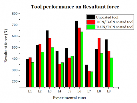
To study of forces (thrust force, feed force and tangential or cutting force) generated during machining of Custom 450 alloy, three types of cutting tools namely, Uncoated, TiAlN/TiCN and TiCN/TiAlN coated tungsten carbide tools are used. The obtained forces are converted to resultant force at its respective experimental trial and it was analysed for its machining performance. The performance of each tool varies and follows a different pattern according to different machining conditions. The different tools performance at different experimental level are plotted and shown in Figure 1. Out of nine trials, almost all the trials (except trial 8) show increased resultant forces for the uncoated carbide tool followed by TiCN/TiAlN and TiAlN/TiCN, respectively. The trial 1 and trial 2 also shows a slight reduced resultant force compared to TiCN/TiAlN and TiAlN/TiCN. It is because, at lower cutting conditions all three cutting tools performs similar to each other with some considerable resultant force variations. Though both the coated tools possess the same coatings, but the order of coatings plays a major role in deciding the machining performance. In that case, TiAlN/TiCN coating outperformed TiCN/TiAlN coating. This is due to dense grain structure with less surface defects like pores, macro particles, voids and obtained greater hardness of the TiAlN coating as a top layer, resulting in less cutting force on the tool. In trail number 4 and 5, the TiCN/TiAlN coating shows lesser resultant force when compared to TiAlN/TiCN coating. The difference in resultant force obtained is found very minimal. On considering other experimental trials, it is seen that TiAlN/TiCN performs better when compared to other two tools. Usage of this coated carbide tool obtains the least machining resultant force of 287.145 N at trial 7 (100 m/min of cutting speed, 0.14 mm/rev of feed rate, 0.5 mm of depth of cut). At this particular machining trial all the tools behave in a same way of lower resultant force, in which TiAlN/TiCN coated tool performs better with lower force. The significance of this particular trial is the increased machining speed. At higher cutting speed, the tool performs better resulting in very low force generation with good surface quality and it is vice-versa in lower machining level. Also, the lower feed rate supports in acquiring this lower force. The higher machining resultant force (736.85 N) is obtained at trial 6 (75 m/min of cutting speed, 0.4 mm/rev of feed rate, 0.5 mm of depth of cut) of Uncoated carbide tool. At this machining condition, the feed rate deteriorates the quality of the machined surface and produces poor cutting force [18, 19].
Figure 1. Resultant cutting forces obtained for different PVD coated and uncoated tools
Table 5. Analysis of variance for resultant cutting forces of PVD coated and uncoated tools
|
Parameter |
DoF |
SS |
MS |
F value |
% Contribution |
|
a) TiAlN/TiCN |
|||||
|
Cutting Speed |
2 |
14101 |
7050 |
2.43 |
17.83 |
|
Feed rate |
2 |
46788 |
23394 |
8.07 |
59.17 |
|
Depth of Cut |
2 |
12377 |
6189 |
2.13 |
15.65 |
|
Error |
2 |
5799 |
2899 |
|
7.33 |
|
Total |
8 |
79064 |
|
|
100 |
|
b) TiCN/TiAlN |
|||||
|
Cutting Speed |
2 |
5219 |
2609 |
0.48 |
4.27 |
|
Feed rate |
2 |
77982 |
38991 |
7.19 |
63.89 |
|
Depth of Cut |
2 |
27999 |
14000 |
2.58 |
22.94 |
|
Error |
2 |
10845 |
5422 |
|
8.88 |
|
Total |
8 |
122045 |
|
|
100 |
|
c) Uncoated |
|||||
|
Cutting Speed |
2 |
14859 |
7430 |
3.23 |
12.89 |
|
Feed rate |
2 |
93090 |
46545 |
20.21 |
80.75 |
|
Depth of Cut |
2 |
2715 |
1357 |
0.59 |
2.35 |
|
Error |
2 |
4606 |
2303 |
|
3.99 |
|
Total |
8 |
115271 |
|
|
100 |
The details of the individual factor contribution in deciding the resultant force during machining of Custom 450 alloy are given as ANOVA in Table 5. From the ANOVA table, it is evident that feed rate is found to be the most important factor in deciding the resultant force in all the three cutting tools. Followed by feed rate, cutting speed influences in deciding force generated during machining process. As the cutting depth increases, more cutting force is required to remove the material which in turn reduces the quality of the work material and reduces the tool life too. Hence the said statement stands behind obtained experimental results [20, 21].
4.2 Surface roughness analysis
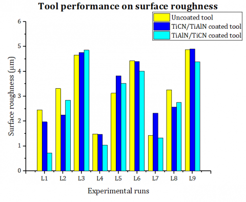
Surface roughness is found to be a most important characteristics in deciding the quality of the machined component. As high the surface quality, more would be the effective usage at the place of application for a required period of time. In the present experimental work, the surface quality of the custom 450 alloy is studied by machining it with Uncoated, TiCN/TiAlN and TiAlN/TiCN coated tool. The obtained results are plotted as bar graph and shown in Figure 2. The plot shows that, the surface roughness follows a different trend for all the machining trials. Out of the 9 trials in all the three cutting tools, the trial which possesses lower feed rate of 0.14 mm/rev exhibits lower cutting force. In machining, feed rate is found to be the most important factor in deciding the surface finish of the material. Lower the feed rate, low the surface roughness obtained and it is opposite for higher feed rate. In addition to machinability parameter, coating characteristics of the cutting tool also contributes in deciding the quality of the machined component [22-24]. Out of three tools, tool having TiAlN/TiCN coating gives very good surface quality when compared to other two. TiAlN/TiCN coating has excellent hardness, improved tribological properties and improved adhesive strength on the base tool. This helps in good machining response using the said coated tool and the performance of TiCN/TiAlN coating and uncoated tool is found lesser. The TiCN/TiAlN coatings has larger grain size, increased pores and cavities, non-uniform structure on its surface resulting in poor performance. As the cutting temperature at the machining zone increases, the heat produced reduces the performance of the cutting tool resulting in increased tool wear and produces poor surface quality on the machined surface.
The results obtained are statistically checked to obtain the individual input factor’s contribution in determining the surface roughness of the machined component and are tabulated in Table 6. The results show that, feed rate is the most significant factor in deciding the surface quality is concerned. While the other two input parameters (depth of cut and cutting speed) are least influential in deciding the surface quality [25, 26]. Higher the feed rate, lower the surface integrity of the machined component. Hence, it is advised to select the feed rate at a lower level to get the enhanced machining quality. The lower surface roughness obtained during machining is 0.791 µm.
Figure 2. Surface roughness plot for different PVD coated and uncoated tools
Table 6. Analysis of variance for surface roughness of PVD coated and uncoated tools
|
Parameter |
DoF |
SS |
MS |
F value |
% Contribution |
|
a) TiAlN/TiCN |
|||||
|
Cutting Speed |
2 |
0.0041 |
0.00204 |
0.09 |
0.02 |
|
Feed rate |
2 |
17.3996 |
8.69982 |
369.65 |
95.07 |
|
Depth of Cut |
2 |
0.8493 |
0.42466 |
18.04 |
4.64 |
|
Error |
2 |
0.0471 |
0.02354 |
|
0.25 |
|
Total |
8 |
18.3001 |
|
|
100 |
|
b) TiCN/TiAlN |
|||||
|
Cutting Speed |
2 |
0.1379 |
0.06894 |
0.19 |
1.00 |
|
Feed rate |
2 |
11.8777 |
5.93883 |
15.94 |
86.22 |
|
Depth of Cut |
2 |
1.0152 |
0.50758 |
1.36 |
7.36 |
|
Error |
2 |
0.7453 |
0.37263 |
|
5.41 |
|
Total |
8 |
13.7760 |
|
|
100 |
|
c) Uncoated |
|||||
|
Cutting Speed |
2 |
0.3225 |
0.16125 |
1.04 |
2.46 |
|
Feed rate |
2 |
12.3290 |
6.16448 |
39.68 |
94.06 |
|
Depth of Cut |
2 |
0.1446 |
0.07229 |
0.47 |
1.10 |
|
Error |
2 |
0.3107 |
0.15536 |
|
2.37 |
|
Total |
8 |
13.1068 |
|
|
100 |
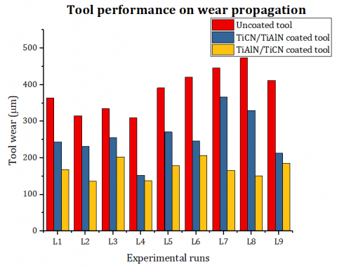
4.3 Tool wear analysis
In the present experimental study, the tool wear obtained during machining of Custom 450 alloy are shown in Figure 3. In all the 9 experimental trials of three different tools, TiAlN/TiCN coated tool exhibits very good wear resistance on the cutting tool. Due to the poor surface quality of the uncoated carbide cutting tool, the maximum tool flank wear is obtained when compared to other two tools. Also, the tool having TiAlN/TiCN coating possess enhanced properties as discussed in previous section. The Al presence in the coatings, enhances the lubrication property during machining operation and Ti and C element presence increases the hardness of the coated carbide tool. Due to the increased depth of cut and heat generation at the machining zone (workpiece-cutting tool interface), thermal effect of the cutting tool takes place and results in significant tool wear. The tools which possess coatings would withstand the said shortcoming and lasts long. While the uncoated tool fails at the earliest without fulfilling the said time of usage. This results in the increased tool wear and higher cutting force generated at the machining region [14]. As the cutting speed increases, the chances of formation built-up edge get reduces and these coatings supports in attaining the same [27]. From the plot showing the flank wear trend, the TiAlN/TiCN coated tool shows very low tool wear value when compared to other two tools. Out of the selected input parameters, the parameter which contributes more in deciding the lower tool wear is found using ANOVA table given in Table 7. From the ANOVA table, for each tool different input parameters contributes in attaining the lower wear value. For TiAlN/TiCN coated tool, feed rate contributes more, for TiCN/TiAlN coated tool depth of cut contributes more and for uncoated tool cutting speed takes the role. Since TiAlN/TiCN coated tool performs better in coating point of view, the ANOVA values of this particular coated tool could be considered for tool wear evaluation. Hence from this result, feed rate is found to be the more influential factor in deciding tool wear criterion [28, 29]. The lower tool wear obtained during machining of custom450 alloy was 136.6 µm for TiAlN/TiCN coated tool.
Figure 3. Tool wear plot for different PVD coated and uncoated tools
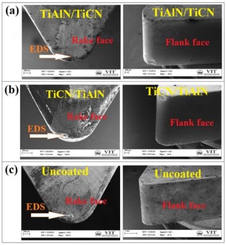
Figure 4. SEM images tools used during machining (a) Rake and flank face of TiAlN/TiCN coated tool-A2B3C2 (L6 Trial), (b) TiCN/TiAlN coated tool-A3B1C2 (L7 Trial), (c) uncoated tool-A3B2C3 (L8 Trial)
Table 7. Analysis of variance for tool wear of PVD coated and uncoated tools
|
Parameter |
DoF |
SS |
MS |
F value |
% Contribution |
|
a) TiAlN/TiCN |
|||||
|
Cutting Speed |
2 |
0.0041 |
0.00204 |
0.09 |
0.02 |
|
Feed rate |
2 |
17.3996 |
8.69982 |
369.65 |
95.07 |
|
Depth of Cut |
2 |
0.8493 |
0.42466 |
18.04 |
4.64 |
|
Error |
2 |
0.0471 |
0.02354 |
|
0.25 |
|
Total |
8 |
18.3001 |
|
|
100 |
|
b) TiCN/TiAlN |
|||||
|
Cutting Speed |
2 |
0.1379 |
0.06894 |
0.19 |
1.00 |
|
Feed rate |
2 |
11.8777 |
5.93883 |
15.94 |
86.22 |
|
Depth of Cut |
2 |
1.0152 |
0.50758 |
1.36 |
7.36 |
|
Error |
2 |
0.7453 |
0.37263 |
|
5.41 |
|
Total |
8 |
13.7760 |
|
|
100 |
|
c) Uncoated |
|||||
|
Cutting Speed |
2 |
0.3225 |
0.16125 |
1.04 |
2.46 |
|
Feed rate |
2 |
12.3290 |
6.16448 |
39.68 |
94.06 |
|
Depth of Cut |
2 |
0.1446 |
0.07229 |
0.47 |
1.10 |
|
Error |
2 |
0.3107 |
0.15536 |
|
2.37 |
|
Total |
8 |
13.1068 |
|
|
100 |
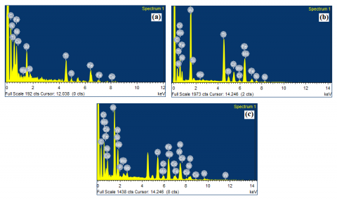
Figure 5. Elemental composition of the machined (a) TiAlN/TiCN coated tool, (b) TiCN/TiAlN coated tool and (c) Uncoated tool
Scanning electron microscopic (SEM) images of tools used in machining of Custom 450 alloy are captured and given in Figure 4. The images clearly shows that TiAlN/TiCN coated tool shows lower tool wear when compared to other. Also, the energy dispersive spectroscopy (EDS) was conducted on the machined tool surface to check for the addition of any work material elements on its surface. The values and the elements confirm the presence of it in Figure 5 and the values are tabulated in Table 8.
Table 8. Elemental composition (EDS analysis)
|
Tools |
Elements (wt%) |
||||||||
|
TiAlN/TiCN |
C |
N |
Si |
Ti |
Ni |
Cu |
Al |
Fe |
Mg |
|
22.54 |
10.11 |
0.71 |
20.78 |
4.36 |
0.64 |
4.02 |
36.44 |
0.40 |
|
|
TiCN/TiAlN |
C |
N |
Si |
Ti |
Cr |
Mn |
Ni |
Mo |
Al |
|
22.53 |
29.83 |
0.32 |
12.95 |
4.19 |
0.27 |
0.97 |
0.33 |
14.29 |
|
|
Fe |
|
|
|
|
|
|
|
|
|
|
14.33 |
|
|
|
|
|
|
|
|
|
|
Uncoated |
C |
Si |
P |
Cr |
Mn |
Ni |
Cu |
Nb |
Mo |
|
45.31 |
1.75 |
0.18 |
9.01 |
0.66 |
14.49 |
1.08 |
0.19 |
1.69 |
|
|
Fe |
W |
Co |
|
|
|
|
|
|
|
|
12.43 |
10.68 |
2.52 |
|
|
|
|
|
|
|
In the previous sections, each and every response are analysed individually to study its parametric contribution for all the three selected tools. Based on the obtained parametric results TiAlN/TiCN coated tool outclassed than other two tools for all three responses. Similarly, the same tool has got different experimental level to obtain the better results for all three responses. Also, all three responses are analysed individually to get individual optimal levels. This creates confusion for the researchers to adopt which machining level for the better response. This gave rise to the introduction of one of the multi criteria decision making (MCDM) model called Utility concept approach, which gives one particular optimal level for multiple responses [30-33].
5.1 Utility concept approach
Utility can be defined as the usefulness of the process with respect to the expectations of the consumers or the customers. In order to meet or satisfy the consumer expectations, the overall performance of the multiple output quality characteristics need to be taken into account along with the relative contribution of selected individual factors. This overall composite index contributes to the overall utility of the process. Hence, the utility refers to the satisfaction of consumers on all the selected attributes. Also, the utility theory works on the basis of utility maximization principle, where the highest satisfaction level is chosen as the best choice (optimal level) by the decision maker [34, 35].
Based on the obtained overall utility index, the best optimal level is chosen for getting the good result on all responses. According to Utility theory, if Xi is the measure of output response effectiveness ‘i’ and there are ‘n’ responses measuring the output, then the joint utility function could be expressed as:
U (X1, X2 ,.......Xn) = f (U1 (X1),U2 (X2 ),.....,Un (Xn))
The summation of individual utilities gives the overall utility function, if the responses are independent and denoted as,
$U=\sum_{i=1}^{n} P i$
where, Pi is the preference number of individual responses.
The preference number could be expressed as follows:
$P_{i}=A * \log \left(\frac{X_{i}}{X_{i}^{\prime}}\right)$
where, Xi is the value of any quality characteristic, i, Xi’ is just acceptable value of quality characteristic, i and A is a constant.
The value A can be found by the condition that if Xi = X* (where X* is the optimal or best value), then Pi = 9. Therefore,
$A=\frac{9}{\log \left(\frac{X^{*}}{X_{i}^{\prime}}\right)}$
The individual obtained utility number is used to obtain overall utility index, through the summation of individual responses. The overall utility index is considered as single response function for optimization. Among various quality characteristics proposed by Taguchi, like, smaller-the-better, larger-the-better and nominal-the-better, the utility function always considers larger-the-better characteristics. The utility index calculated for all three types of tools are shown in Tables 9, 10 and 11.
Based on the above tabulations, it is clear that through multi criteria decision making process, all three types of tools showed experimental trial number 4 as the best optimal level for obtaining better results. The machining condition at trial 4 is 75 m/min of cutting speed, 0.14 mm/rev of feed rate and 0.75 mm of depth of cut. This experimental level is selected based on the higher utility index number. For the obtained overall utility index, the Analysis of variance is performed to know the parameter contribution for all three types of tool. Based on the ANOVA analysis in Tables 12, 13 and 14, out of three input parameters in all three selected tools, feed rate contributes more in deciding the output responses.
Table 9. Overall utility index of uncoated carbide tool
|
Experimental trials |
Experimental output |
Preference number |
Overall Utility Index |
||||
|
RF (N) |
SR (µm) |
TW (µm) |
RF (N) |
SR (µm) |
TW (µm) |
||
|
L1 |
398.5 |
2.4512 |
364.4 |
7.3814 |
5.0343 |
5.5241 |
17.9398 |
|
L2 |
525.41 |
3.3120 |
315.5 |
4.0614 |
2.8307 |
8.5732 |
15.4653 |
|
L3 |
651.23 |
4.6589 |
334.5 |
1.4833 |
0.3325 |
7.3357 |
9.1516 |
|
L4 |
472.65 |
1.4880 |
309.2 |
5.3322 |
8.6886 |
9.0000 |
23.0208 |
|
L5 |
495.36 |
3.1260 |
391.2 |
4.7686 |
3.2539 |
4.0224 |
12.0449 |
|
L6 |
736.85 |
4.4315 |
421.2 |
0.0000 |
0.6989 |
2.4588 |
3.1578 |
|
L7 |
348.25 |
1.4260 |
445.5 |
9.0000 |
9.0000 |
1.2720 |
19.2720 |
|
L8 |
486.32 |
3.2596 |
473.1 |
4.9898 |
2.9475 |
0.0000 |
7.9372 |
|
L9 |
572.52 |
4.8754 |
412 |
3.0302 |
0.0000 |
2.9262 |
5.9564 |
Table 10. Overall Utility index of TiCN/TiAlN coated carbide tool
|
Experimental trials |
Experimental output |
Preference number |
Overall Utility Index |
||||
|
RF (N) |
SR (µm) |
TW (µm) |
RF (N) |
SR (µm) |
TW (µm) |
||
|
L1 |
412.63 |
1.971 |
243.9 |
5.3544 |
6.7949 |
4.1766 |
16.3259 |
|
L2 |
531.25 |
2.245 |
232.2 |
2.6167 |
5.8279 |
4.6794 |
13.1241 |
|
L3 |
584.25 |
4.755 |
255.7 |
1.5862 |
0.2417 |
3.6934 |
5.5213 |
|
L4 |
356.9 |
1.466 |
152.2 |
6.9266 |
9.0000 |
9.0000 |
24.9266 |
|
L5 |
410.57 |
3.825 |
270.7 |
5.4087 |
1.8612 |
3.1103 |
10.3802 |
|
L6 |
676.37 |
4.406 |
245.9 |
0.0000 |
0.8090 |
4.0931 |
4.9020 |
|
L7 |
294.74 |
2.324 |
366.9 |
9.0000 |
5.5689 |
0.0000 |
14.5689 |
|
L8 |
585.25 |
2.572 |
329.6 |
1.5678 |
4.8144 |
1.0966 |
7.4788 |
|
L9 |
471.25 |
4.912 |
212.9 |
3.9150 |
0.0000 |
5.5670 |
9.4821 |
Table 11. Overall Utility index of TiAlN/TiCN coated carbide tool
|
Experimental trials |
Experimental output |
Preference number |
Overall Utility Index |
||||
|
RF (N) |
SR (µm) |
TW (µm) |
RF (N) |
SR (µm) |
TW (µm) |
||
|
L1 |
370.12 |
0.719 |
168.25 |
6.1562 |
9.0000 |
4.4826 |
19.6388 |
|
L2 |
461.24 |
2.847 |
136.6 |
3.6904 |
2.5142 |
9.0000 |
15.2047 |
|
L3 |
501.45 |
4.855 |
202.58 |
2.7542 |
0.0000 |
0.4574 |
3.2117 |
|
L4 |
368.54 |
1.043 |
137.58 |
6.2042 |
7.2444 |
8.8450 |
22.2937 |
|
L5 |
424.57 |
3.524 |
178.24 |
4.6185 |
1.5093 |
3.2322 |
9.3600 |
|
L6 |
641.21 |
4.006 |
206.9 |
0.0000 |
0.9054 |
0.0000 |
0.9054 |
|
L7 |
287.14 |
1.327 |
165.8 |
9.0000 |
6.1100 |
4.8005 |
19.9106 |
|
L8 |
450.12 |
2.754 |
151.24 |
3.9640 |
2.6707 |
6.7930 |
13.4276 |
|
L9 |
410.24 |
4.385 |
184.74 |
5.0032 |
0.4796 |
2.4558 |
7.9386 |
Table 12. ANOVA for uncoated tool
|
Source |
DoF |
SS |
MS |
F-Value |
P-Value |
|
Cutting speed (m/min) |
2 |
14.72 |
7.364 |
0.35 |
0.743 |
|
Feed rate (mm/rev) |
2 |
296.74 |
148.3 |
6.96 |
0.126 |
|
Depth of cut (mm) |
2 |
2.90 |
1.4 |
0.07 |
0.936 |
|
Error |
2 |
42.65 |
21.3 |
||
|
Total |
8 |
357.03 |
Table 13. ANOVA for TiCN/TiAlN coated tool
|
Source |
DoF |
SS |
MS |
F-Value |
P-Value |
|
Cutting speed (m/min) |
2 |
12.734 |
6.367 |
0.18 |
0.850 |
|
Feed rate (mm/rev) |
2 |
225.514 |
112.757 |
3.13 |
0.242 |
|
Depth of cut (mm) |
2 |
4.929 |
2.464 |
0.07 |
0.936 |
|
Error |
2 |
72.073 |
36.036 |
||
|
Total |
8 |
315.250 |
Table 14. ANOVA for TiAlN/TiCN coated tool
|
Source |
DoF |
SS |
MS |
F-Value |
P-Value |
|
Cutting speed (m/min) |
2 |
12.954 |
6.477 |
0.39 |
0.721 |
|
Feed rate (mm/rev) |
2 |
413.371 |
206.686 |
12.34 |
0.075 |
|
Depth of cut (mm) |
2 |
1.478 |
0.739 |
0.04 |
0.958 |
|
Error |
2 |
33.499 |
16.750 |
||
|
Total |
8 |
461.302 |
This manuscript, contributes the machining studies of TiAlN/TiCN, TiCN/TiAlN PVD coated and uncoated tungsten tools during dry or green turning operation of custom 450 alloy. The performance evaluations of the PVD coatings were analysed with the output results such as resultant forces obtained during machining, surface roughness of the workpiece and tool wear. The optimum levels for the coated and uncoated tungsten carbide tools were observed based on single response optimization, ANOVA analysis and multi criteria decision making approach. The results obtained are listed below:
[1] Chen, D.Y., Tsai, C.H., Yang, W.J., Liu, D.W., Hsu, C.Y. (2016). Reactive co-sputter deposition and properties of CrAlSiN hard films for enhancement of cutting tools. International Journal of Refractory Metals and Hard Materials, 58: 110-116. https://doi.org/10.1016/j.ijrmhm.2016.04.006
[2] Kuo, C.C., Chen, Y.R., Tong, C.Y., Lee, J.W. (2013). A low-cost optical inspection system for rapid surface roughness measurements of CrCN hard films. Optik, 125(2): 903. https://doi.org/10.1016/j.ijleo.2013.05.003
[3] Kumar, T.S., Ramanujam, R., Vignesh, M., Rohith, D., Manoj, V., Sankar, P.H. (2019). Comparative machining studies on custom 450 alloy with TiCN, TiAlN coated and uncoated carbide tools using Taguchi-Fuzzy logic approach. Materials Research Express, 6(6): 066411. https://doi.org/10.1088/2053-1591/ab0d96
[4] Chen, Y., Du, H., Chen, M., Yang, J., Xiong, J., Zhao, H.B. (2016). Structure and wear behavior of AlCrSiN-based coatings. Applied Surface Science, 370: 176-183. https://doi.org/10.1016/j.apsusc.2015.12.027
[5] Devillez, A., Schneider, F., Dominiak, S., Dudzinski, D., Larrouquere, D. (2007). Cutting forces and wear in dry machining of Inconel 718 with coated carbide tools. Wear, 262(7-8): 931-942. https://doi.org/10.1016/j.wear.2006.10.009
[6] Hamdan, A., Sarhan, A.A.D., Hamdi, M. (2012). An optimization method of the machining parameters in high-speed machining of stainless steel using coated carbide tool for best surface finish. International Journal of Advanced Manufacturing Technology, 58: 81-91. https://doi.org/10.1007/s00170-011-3392-5
[7] Ciftci, I. (2006). Machining of austenitic stainless steels using CVD multi-layer coated cemented carbide tools. Tribology International, 39(6): 565-569. https://doi.org/10.1016/j.triboint.2005.05.005
[8] Nouari, M., Ginting, A. (2006). Wear characteristics and performance of multi-layer CVD-coated alloyed carbide tool in dry end milling of titanium alloy. Surface and Coatings Technology, 200(18-19): 5663-76. https://doi.org/10.1016/j.surfcoat.2005.07.063
[9] Arunachalam, R.M., Mannan, M.A., Spowage, A.C. (2004). Surface integrity when machining age hardened Inconel 718 with coated carbide cutting tools. International Journal of Machine Tools and Manufacturing, 44(14): 1481-91. https://doi.org/10.1016/j.ijmachtools.2004.05.005
[10] Fox-Rabinovich, G.S., Yamamoto, K, Aguirre, M.H., Cahill, D.G., Veldhuis, S.C., Biksa, A. (2010). Multi-functional nano-multilayered AlTiN/Cu PVD coating for machining of Inconel 718 superalloy. Surface and Coatings Technology, 204(15): 2465-71. https://doi.org/10.1016/j.surfcoat.2010.01.024
[11] Khrais, S.K., Lin, Y.J. (2007). Wear mechanisms and tool performance of TiAlN PVD coated inserts during machining of AISI 4140 steel. Wear, 262(1-2): 64-9. https://doi.org/10.1016/j.wear.2006.03.052
[12] Sampath Kumar, T, Ramanujam, R., Vignesh, M., Tamiloli, N., Sharma, N., Srivastava, S. (2018). Comparative evaluation of performances of TiAlN, AlCrN, TiAlN/AlCrN coated carbide cutting tools and uncoated carbide cutting tools on turning Inconel 825 alloy using Grey Relational Analysis. Sensors Actuators A: Physical, 279: 331-42. https://doi.org/10.1016/j.sna.2018.06.041
[13] Bhatt, A., Attia, H., Vargas, R., Thomson, V. (2010). Wear mechanisms of WC coated and uncoated tools in finish turning of Inconel 718. Tribology International, 43(5-6): 1113-21. https://doi.org/10.1016/j.triboint.2009.12.053
[14] Chinchanikar, S., Choudhury, S.K. (2013). Investigations on machinability aspects of hardened AISI 4340 steel at different levels of hardness using coated carbide tools. International Journal of Refractory Metals and Hard Materials, 38: 124-33. https://doi.org/10.1016/j.ijrmhm.2013.01.013
[15] Sampath Kumar, T., Vinoth Jebaraj, A., Shankar, E., Tamiloli, N., Sivakumar, K. (2019). Metallurgical and mechanical characterization of TiCN/TiAlN and TiAlN/TiCN bilayer nitride coatings. Surfaces and Interfaces, 15: 256-64. https://doi.org/10.1016/j.surfin.2019.03.001
[16] Sampath Kumar, T., Balasivanandha Prabu, S., Manivasagam, G., Padmanabhan, K.A. (2014). Comparison of TiAlN, AlCrN, and AlCrN/TiAlN coatings for cutting-tool applications. International Journal of Minerals Metallurgy and Materials, 21: 796-805. https://doi.org/10.1007/s12613-014-0973-y
[17] Sampath Kumar, T., Jebaraj, A.V., Sivakumar, K., Shankar, E., Tamiloli, N. (2017). Characterization of TiCN coating synthesized by the plasma enhanced physical vapour deposition process on a cemented carbide tool. Surface Review and Letters, 25(8): 1950028. https://doi.org/10.1142/S0218625X19500288
[18] Ivashchenko, L.A., Rusakov, G.V., Ivashchenko, V.I., Porada, O.K. (2004). Hard coatings on cutting tools. Powder Metallurgy and Metal Ceramics, 43: 606-10. https://doi.org/10.1007/s11106-005-0028-z
[19] Veprek, S., Mukherjee, S., Männling, H.D., He, J. (2003). On the reliability of the measurements of mechanical properties of superhard coatings. Materials Science and Engineering: A, 340(1-2): 292-297. https://doi.org/10.1016/S0921-5093(02)00195-8
[20] Jindal, P.C., Santhanam, A.T., Schleinkofer, U., Shuster, A.F. (1999). Performance of PVD TiN, TiCN, and TiAlN coated cemented carbide tools in turning. International Journal of Refractory Metals and Hard Materials, 17(1-3): 163-70. https://doi.org/10.1016/S0263-4368(99)00008-6
[21] Siow, P.C., Ghani, J., Ghazali, M.J., Jaafar, T.R., Selamat, M.A., Che Haron, C.H. (2013). Characterization of TiCN and TiCN/ZrN coatings for cutting tool application. Ceramics International, 39(2): 1293-8. https://doi.org/10.1016/j.ceramint.2012.07.061
[22] Zhang, S., Zhu, W. (1993). TiN coating of tool steels: A review. Journal of Materials Processing and Technology, 39(1-2): 165-77. https://doi.org/10.1016/0924-0136(93)90016-Y
[23] Bobzin, K. (2017). High-performance coatings for cutting tools. CIRP Journal of Manufacturing Science and Technology, 18: 1-9. https://doi.org/10.1016/j.cirpj.2016.11.004
[24] He, N., Li, H.X., Ji, L., Liu, X.H., Zhou, H.D., Chen, J.M. (2016). High temperature tribological properties of TiAlSiN coatings produced by hybrid PVD technology. Tribology International, 98: 133-43. https://doi.org/10.1016/j.triboint.2016.02.034
[25] Long, Y., Zeng, J.J., Yu, D.H., Wu, S.H. (2014). Microstructure of TiAlN and CrAlN coatings and cutting performance of coated silicon nitride inserts in cast iron turning. Ceramics International, 40(7): 9889-94. https://doi.org/10.1016/j.ceramint.2014.02.083
[26] Sampath Kumar, T., Balasivanandha Prabu, S., Sorna Kumar, T. (2016). Comparative evaluation of performances of TiAlN-, AlCrN- and AlCrN/TiAlN-coated carbide cutting tools and uncoated carbide cutting tools on turning EN24 alloy steel. Journal of Advanced Manufacturing Systems, 16(3): 237-261. https://doi.org/10.1142/S0219686717500159
[27] Chetan, Behera, B.C., Ghosh, S., Rao, P.V. (2016). Wear behavior of PVD TiN coated carbide inserts during machining of Nimonic 90 and Ti6Al4V superalloys under dry and MQL conditions. Ceramics International, 42(13): 14873-85. https://doi.org/10.1016/j.ceramint.2016.06.124
[28] Suresh, R., Basavarajappa, S., Gaitonde, V.N., Samuel, G.L. (2012). Machinability investigations on hardened AISI 4340 steel using coated carbide insert. International Journal of Refractory Metals and Hard Materials, 33: 75-86. https://doi.org/10.1016/j.ijrmhm.2012.02.019
[29] Venkatesan, K., Ramanujam, R., Joel, J., Jeyapandiarajan, P., Vignesh, M., Tolia, D.J., Krishna, R.V. (2014). Study of cutting force and surface roughness in machining of Al alloy hybrid composite and optimized using response surface methodology. Procedia Engineering, 97: 677-86. https://doi.org/10.1016/j.proeng.2014.12.297
[30] Nayak, B.B., Mahapatra, S.S. (2014). A utility concept approach for multi-objective optimization of taper cutting operation using WEDM. Procedia Engineering, 97: 469-78. https://doi.org/10.1016/j.proeng.2014.12.271
[31] Kansal, H.K., Singh, S., Kumar, P. (2006). Performance parameters optimization (multi-characteristics) of powder mixed electric discharge machining (PMEDM) through Taguchi’s method and utility concept. Indian Journal of Engineering and Materials Sciences, 13: 209-216.
[32] Chakravorty, R., Gauri, S.K., Chakraborty, S. (2012). A modified principal component analysis-based utility theory approach for optimisation of correlated responses of EDM process. International Journal of Engineering Science and Technology, 4(2): 34-45. http://dx.doi.org/10.4314/ijest.v4i2.3
[33] Vignesh, M., Ramanujam, R. (2018). Response optimisation in wire electrical discharge machining of AISI H11 tool steel using Taguchi – GRA approach. in International Journal of Machining and Machinability of Materials, 20(5): 474-495. http://dx.doi.org/10.1504/IJMMM.2018.10017184
[34] Routara, B.C., Mohanty, S.D., Datta, S., Bandyopadhyay, A., Mahapatra, S.S. (2010). Optimization in CNC end milling of UNS C34000 medimum leaded brass with multiple surface roughnesses characteristics. Sadhana, 35: 619-629. https://doi.org/10.1007/s12046-010-0041-x
[35] Kumar, J., Khamba, J.S. (2010). Multi-response optimisation in ultrasonic machining of titanium using Taguchi’s approach and utility concept. International Journal of Manufacturing Research, 5(2): 139-60. https://doi.org/10.1504/IJMR.2010.031629