Neethu Vijayan | Surya Akshar Raj | Veerakumar Muthirulan | Krishnamurthy H. Sachidananda*
OPEN ACCESS
Polishing is a surface machining technique to produce a high-quality finished surface on the product. It is a multistage process, in which each subsequent stage uses a finer abrasive. This paper aims to design and fabricate a polishing machine that performs polishing stages continuously, eliminating the idle time in the polishing process. The designed machine consists of four spindle heads, each of which carries a unique flap wheel. The flap wheels can raise or lower according to the size of the workpiece to be polished. Three types of rollers were adopted in the machine: a mild steel roller coated with heat resistant rubber, a hylam roller and a nylon roller. A pneumatic clamping system was placed at the feeder to fix and hold the workpiece. In addition, the compressor pressure is regulated by a pressure regulator. A prototype of the polishing machine was fabricated according to the design, and used to polish several types of workpieces. The results show that this machine can polish stainless-steel flat bars, square tubes and rectangular tubes into 10mm-150mm width products, operate at a high speed of 2,000~3,000 rpm, and, most importantly, execute multiple polishing operations continuously. The proposed polishing machine is helpful to the automation of the polishing industry.
polishing, surface roughness, surface finish, machining
Polishing is a process of generating smooth and shiny surface on the workpiece [1]. This operation is mainly done on the face of components in order to improve the surface finish. Also, it is often done to further improve the looks by creating good surface finish, prevent contamination of work pieces, remove oxidation, create a reflective surface, or prevent corrosion [2]. The surface finish obtained depends on grit size of the abrasive used [3]. So, polishing is a multistage process and starts with a rough grit size abrasive and each subsequent stage of polishing uses a finer higher grit abrasive until the intended surface finish is obtained. The rough grit size removes the imperfections on the work piece such as pits, nicks, lines and scratches from the workpiece and the finer abrasives leaves progressively finer lines that are not visible to the naked eye [4]. The main need of this research work is to design a polishing machine which is capable of polishing the specimen in a continuous sequence to reduce the idle time of the machine. This helps in fast movement of the workpiece from rough size polishing to very good surface finish at one continuous operation.
Based on the above research problem some of the literature related to design and fabrication of polishing machine has been studied. Erinle et al. [5] has studied and developed metallographic polishing machine. The main aim of this study is to develop a machine which can polish metal in order to get a flat and smooth surface. They concluded that their developed machine has ability to grind and polish metal components. Avinash et al. [6] has studied and designed metallographic lab setup. They developed a laboratory equipment to polish metal in order to achieve good surface finish. From this research work they concluded that these types of machine are available in the market in order to obtain good surface finish. Barbuto [7] has developed procedures in order to automate polishing of ceramics. They studied these procedures considering Struers automatic polishing machine. They concluded that their procedure produces a very high-quality product. Sagar et al. [8] has studied performance evaluation of polishing machines. They discussed the design consideration of polishing machine and they concluded that the polishing machine they developed has performed better in producing shining surface on the specimen. Oyetunji et al. [9] has developed a laboratory polishing machine. They developed their own indigenous technology to develop polishing machine in order to polish metallic materials. They concluded that there developed machine can be used by the end users in the metallography industry. Zavid et al. [10] has developed a polishing machine which works based on parallel-kinematic system. They developed a hexapod which was held in the machine frame in order to drive the polishing tool. They concluded that the designed hexapod can polish steel material with good surface roughness. Bhaskar et al. [11] have studied the metal removal rate considering different types of emery paper during polishing. They fabricated a polishing machine and tested the effectiveness. They concluded that these types of machine can be used to polish metal components. Wang, G.L. and Wang, Y.Q. [12] has developed a special polishing machine. They studied the different process parameters considering surface roughness and polishing efficiency using Taguchi method. They concluded by giving optimal combination of process parameters. Fernandez et al. [13] has developed a newer methodology for abrasive polishing process. They studied the feasibility of polishing method using robotics. They concluded that it is possible to predict the final surface quality using the methodology they developed. Wu et al. [14] have studied M300 steel in considering surface quality during polishing. They used a ball type abrasive tool polishing and then they optimized considering surface roughness and material removal rate. They concluded the optimization process using confirmatory tests. Qu et al. [15] have studied dynamic design process in grinding and polishing. The optimization process was done considering genetic optimization in FEA software. They concluded from their analysis that dynamic properties have been enhanced significantly.
From the above literature review it is observed that many researchers have put lot of effort in designing a polishing machine and tried to optimize parameters in order to obtain good surface finish. Hence, in this research work an attempt has been made to design a polishing machine which is capable of performing a continuous sequence of operations starting from rough grit size to good surface finish. Also, in this research work a flat type polishing machine have been considered and an attempt have also been made to improve the belt conveyor system by replacing it with a chain drive system which produces less load on the shaft. Also, single head wheels have been replaced with four head wheels in order to obtain continuous operation to save time and give uniform polish as well as to increase the polishing length. Some of the main key components used in the design and fabrication of polishing machine is the proximity sensors and the screw jacks. This proximity sensors have been used in order to safeguard any worker going very near to the machine while in operation and screw jack is used to hold the heavier workpiece while polishing operation is under progress.
The main purpose of developing this polishing machine is to polish workpieces continuously in a stretch. The polishing machine which was used previously was performing operations intermittently. For example, in order to polish the workpiece surface was initially polished with rough grit size and then the polishing heads needs to be replaced with fine polishing head and operations needs to be performed. Hence, using this machine it is possible to perform the polishing operations continuously with good surface finish.
So in this research work in order to develop polishing machine, the research paper is organized into methodology section, experimental details, design of various components of the machine, the proximity sensors and the sliding guard.
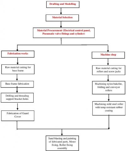
In order to manufacture this polishing machine, the following methodology have been adopted. The main fabrication of the polishing machine is broken down into miscellaneous components and different processes and fabrication have been performed and then later assembled step by step. Also, the different step by step process in order to accomplish this polishing machine is simplified and prepared in the form of flow chart as shown in Figure 1.
Figure 1. Workflow chart
The material selection and the material procurement like pneumatic valve fittings and cylinders have been selected based on the requirement. The fabrication of raw material cutting for base frame, drilling and threading support, bracket holes, raw material cutting for rollers and screw jacks, machining of nylon Bakelite, holding and conveyor rollers, machining of mild steel roller with temperature resistant rubber coating etc. And fabrication of the guard cover has been performed. The material for the base frame considered is mild steel due to its high weldability, machineability, high toughness and good elastic strength.
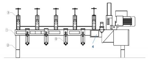
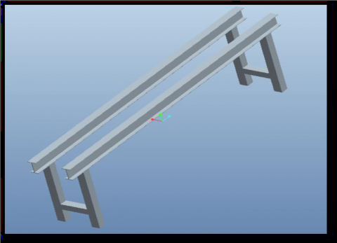
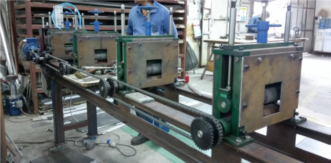
Figure 2 shows the 2D view of the polishing machine. The dimensions of this polishing machine are length 3000 mm, width 400 mm, height 800 mm and mass 750 Kgs. Figure 4 shows the base frame and consists of two I beam (Figure 3) bolted to the supporting legs. The I beam is 150 mm in height and 75 mm in width. The supporting legs are made up of hollow square tubes of 75 mm width and 800 mm height. The screw jack holds the polishing heads and it is also possible to adjust the distance between each screw jack. The roller guide supports in holding the work in place and are kept at 600 mm. The roller used are hylam roller and mild steel roller coated with heat resistant.
Figure 2. 2D Front view of the polishing machine (1. Base frame 2. Supporting leg 3. Roller guide 4. Feeder 5. Screw Jack)
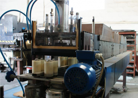
The machine has four spindle heads and the polishing wheels of different grit are placed at each spindle. The flap wheels rotate at 3000 rpm and is mounted on the screw jack and the height of these screw jacks can be adjusted accordingly. The nylon roller guides the material into the feeder. A pneumatic clamp coated with heat resistant rubber and Bakelite rollers are used as conveyor rollers. A sliding guard cover made of mild steel prevents contact between hazardous moving parts and body or clothing and protects objects falling into machinery.
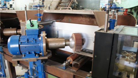
The experiments were performed on CNC turning machine (MTAB Flex) and the experimental setup is as shown in Figure 2. The experiments were conducted as per Taguchi’s L27 orthogonal array. The corresponding dimension of the aluminum workpiece considered for experimentation was having a diameter of 25 mm and length of 100 mm. The specimen was clamped onto the chuck of the machine. The surface roughness measurement was done using surface roughness tester (TR110) which is pocket sized surface roughness measuring instrument suited for on the spot surface measurement quickly. The specifications of the surface roughness instrument are as shown in Table 2. The specimen before machining and after machining is as shown in Figure 2.
Figure 3. Mild steel I- Beams
Figure 4. Base frame
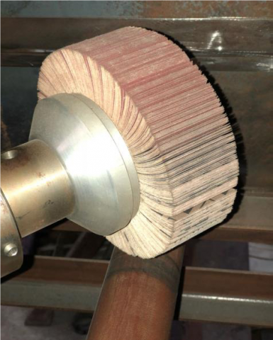
The flap wheels used for this machine is aluminum oxide emery cloth. The reddish-brown grit covering this paper is synthetic. The synthetic grit is harder than flint or garnet and cuts quite well (Refer Figure 5).
Figure 5. Grit flap wheel
Some of the advantages of using the flap wheels is as follows - Aluminum oxide blend offers excellent cut rate and life for better performance, Also X-Weight cotton backing withstands aggressive sanding and grinding. The resin bonding resists thermal and chemical deterioration for extended wheel life, Abrasive flap design provides a soft and smooth cut on rounded or irregular surfaces, includes a grind-aid to provide cooler running on stainless-steel and other metals, The separate flaps each attack the workpiece surface at a slightly different angle, and this varies slightly with tool angle. This avoids the common problem with flat sheets where they produce repeated identical scratches.
There are 4 flap wheels used in this machine for the metal finishing operation. The diameter of the flap wheel is 153 mm, thickness is 51 mm and it rotates at 3000 rpm. The dimensional drawing of the flap wheel is as shown in Figure 6 and the grit size of each flap wheel is shown in Table 1.
Figure 6. Dimensions of the flap wheel
Table 1. Grit size of each flap wheel
|
Wheels |
1 |
2 |
3 |
4 |
|
Grit size |
100 |
320 |
400 |
800 |
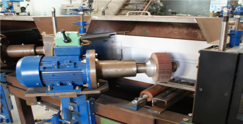
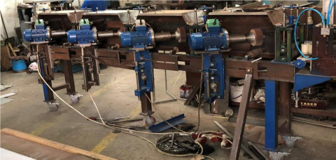
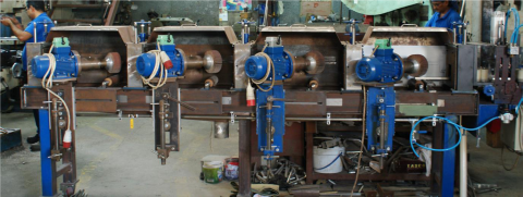
This polishing machine is driven by a 3 phase AC induction motor and the details of the specification is as shown in Table 2. This machine uses four induction motors for running the four different grit flap wheels. The main advantages of using AC induction motors (refer Figure 7) are simple and rugged construction, low cost, ease of maintenance and ability to directly connect to an AC power source. The power requirements of the motor depend upon polishing speed and pressure/load. The motors are placed at an angle of 45 degree in order to obtain smooth finish. These motors are mounted on the screw jacks so that the height could be adjusted accordingly.
Table 2. Specifications of AC induction motor
|
Voltage (V) |
Horse power |
Electric Power (kW) |
Speed (Rpm) |
Frequency (Hz) |
Brand |
|
220/380 |
1 |
0.75 |
2840 |
50 |
Guanglu |
Figure 7. AC motor with flap wheel
5.1 Worm gear motors
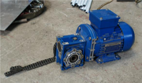
Worm gear motor box is used to run the chain conveyor used in the machine. The specifications of the motor are given in Table 3. In this machine a chain drive is used instead of a belt drive as chains are cheaper to replace. Also, if there is a slackness it is possible to add links to tighten the chains and have higher efficiency as compared to belt drive. It is also possible to obtain high velocity ratio and occupies less space as compared to belt drive. The worm gearbox motor and the details of the chain link is as shown in Figure 8. There are 8 sprockets connected to the roller guides and one sprocket connecting the remaining sprockets to the main motor. Each sprocket has 32 teeth and has a diameter of 88.9 mm.
Table 3. Specifications of worm gear motor
|
Voltage (V) |
Horse power |
Electric Power (kW) |
Speed (Rpm) |
Frequency (Hz) |
Brand |
|
220/380 |
1 |
0.37 |
1340 |
50 |
Guanglu |
Figure 8. Worm gearbox motor
5.2 Variable frequency drive
Figure 9 shows the variable frequency drive and is used to control AC motor speed and torque by varying motor input frequency voltage. The specifications of the variable frequency drive are as shown in Table 4.
Table 4. Specifications of VFD
|
Phase |
Voltage |
Output power (kW) |
Brand |
|
1 |
220 |
0.75 |
Delta |
Figure 9. Variable frequency drive (VFD)
5.2 Proximity sensors
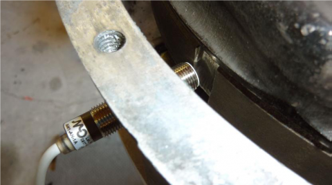
The proximity sensor shown in Figure 10 is a sensor which can detect the possible presence of nearby objects despite not having any physical contact. This proximity sensors usually emits an electromagnetic field or transmit a beam of electromagnetic radiation and looks for possible changes in the field or return signal. Proximity sensors have a high reliability and good functional life because of the absence of mechanical parts and lack of physical contact between the sensor and the sensed object. This proximity sensors have a specific distance within which the objects can be sensed. In case of this polishing machine one sensor is installed inside every section of polishing head guard. Only one sensor is activated at a time based on the position of the metal bar and all other sensors will be idle until the bar passes through the first section. After the bar passes through the first polishing section, then the second proximity sensor will be active and in turn first proximity sensor will be idle. This helps in varied distribution of power across the polishing heads and negates any wastage of energy.
Figure 10. Proximity Sensors
5.3 Miscellaneous components
5.3.1 Base frame
The base frame is a supporting structure with four stabilizing legs of 800 mm height and holds parts such as screw gauge, roller guides, feeder, flap wheel etc. The base frame is made of mild steel because of its weldability and machinability (refer Figure 11).
5.3.2 Screw jacks
Screw jack consists of a heavy-duty vertical screw with the polishing wheel mounted on its top, which screws into a threaded hole in a stationary support frame. A rotating collar on the head of the screw has holes into which the handle, a metal bar fits. When the handle is turned counterclockwise the screws moves further on the base compressing the load resting on the load table (Refer Figure 12).
Figure 11. Base frame holding all the components
Figure 12. Screw jacks
5.3.3 Rollers
The purpose of guide roller is to maintain the integrity and alignment of object while in motion. By placing a guide roller into position on any moving object, it will follow the path of the roller and track in a straight and orderly manner. The ability to roll allows for an easy movement with least possible resistance. This also prevents unnecessary damage to the object being guided into position. Figure 13 shows the nylon guide roller.
5.3.4 Pneumatic systems
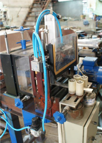
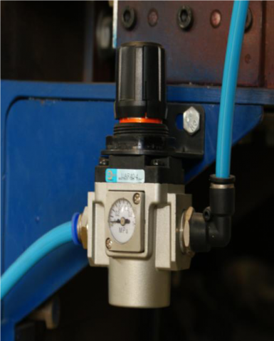
Pneumatic clamps (refer Figure 14) use air-actuated cylinders to operate the clamping action. The polishing machine designed uses pneumatic clamping system to hold the workpiece. The pressure regulator which is shown in Figure 15 is used to regulate the compressor pressure.
Figure 13. Nylon guide rollers
Figure 14. Pneumatic clamp
Figure 15. Pressure regulator
5.3.5 Sliding guard
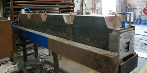
The sliding metal guard is a safety component installed for the safety of the user/operator of the polishing machine. The metal guard is constructed out of simple steel by simple processes of cutting, bending and welding the parts together to attain the optimized shape and dimensions. This polishing machine consists of two guards namely chain guard and polishing head guard as shown in Figure 16 and Figure 17. The chain guard is a rather simple mechanism since the chain is a moving rotary part and it encompasses high probability of a worker entanglement or equipment entanglement in case of lapse of attention.
Figure 16. Chain guard
Figure 17. Sliding polishing head guard
5.3.6 polishing head guard
Polishing head guard (Refer Figure 17) works on same purpose of safeguarding the humans involved in the polishing process and reducing the probability of damage to the machine. However, unlike the chain guard above, the polishing head guards are electrically connected to the motor by a trip switch. Unless the guard is completely closed, the circuit will not complete and the motor will not start. This minor addition makes the whole process much safer and is great advantage to the company if being used by a trainee.
6.1 Base frame fabrication
The I-beams are one of the three integral parts of the base frame assembly. These beams are made of mild steel metal. The I beam are cut using bandsaw to the desired length in sets of two and fabrication work has been performed which serves as a bed frame on which all the components will be mounted.
6.2 Supporting legs
The supporting legs have been fabricated and the I beam are mounted on these support legs. These supporting legs are made of 150 mm x 75 mm hollow square tubes. After this a third leg is welded to the hollow tubes for support and better load distribution and stability.
6.3 Flat plate
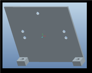
The side plate (Refer Figure 18) is the final addition to the base frame assembly. The fabrication process of side plate comprised of both welding and drilling procedures. The side plate is first cut to the required dimension using bandsaw cutting process and then four holes are drilled in pairs opposite to each other. These holes are threaded which helps in the later stages in securing the pneumatic valve systems and the guide rollers. Finally, all these parts such as screw gauge, roller guides, feeder, flap wheels are mounted and assembled to make the base frame (Refer Figure 19).
Figure 18. Side plate
Figure 19. Base frame assembly
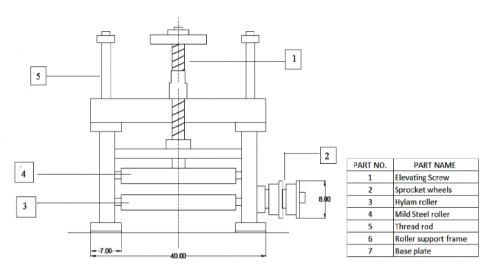
6.4 Fabrication of roller guide assembly
Figure 20 shows the front view of the roller guide assembly. It consists of elevating screw which is a threaded and passes through a threaded nut and is made of mild steel. This elevated screw is further connected to the mild steel roller. In this assembly there are two rollers out of which one is mild steel roller and the other is hylam roller. Mild steel roller is connected to the elevating screw and the position of these mild steel rollers is based on the input of elevating screw and allows different workpieces to be adjusted which is of different dimensions. The roller guide mounted on the base frame is as shown in Figure 21.
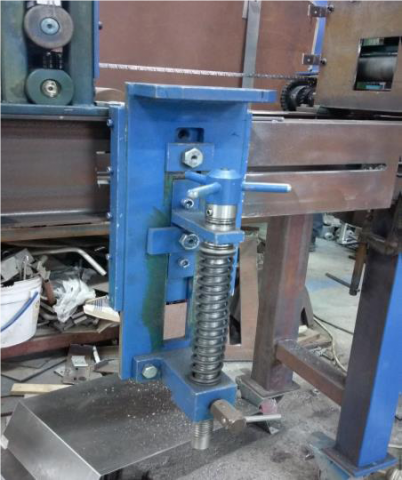
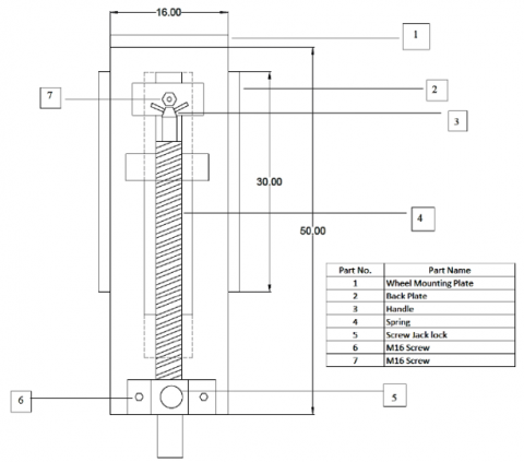
6.5 Fabrication of screw jack
The front view of the screw jack is as shown in Figure 22. The flap wheels are mounted on the screw jack. The backplate lays the foundation for the screw jack assembly. It is a metal plate cut to the required dimensions of 300 mm x 160 mm and is bolted on to the base frame assembly using bolts and the recess in the base frame design. This back plate is fixed but offers sliding slots onto which the front frame is mounted. The front frame assembly is designed to move in vertical direction moving on the sliding slot arrangement provided on the back plate. Further, the front plate can be secured to a permanent height with the help of locking M16 bolts. This front plate is physically bolted and attached to a screw jack in such a way that the rotary motion of the screw jack dictates the vertical movement of the entire front plate. The screw jack is a vital part of this assembly. The screw jack also supports a helical spring coil of diameter 25 mm and wire diameter of 3 mm to support the load by resisting the screw jack rotary motion. Depending on the size of the work being polished, the screw jack assembly can be elevated and lowered on demand and then be locked into position using the screw jack lock and is also considered to be a safety feature in order to assure that the screw jack does not change position during the polishing process which would affect the surface finish. The final assembly of the machine assembled is as shown in Figure 23. From the design and fabrication of the polishing machine, it can be observed that the surface roughness obtained after performing the polishing operation was very good and it was observed that the surface finish was very similar to the other polishing machine. Also, it is possible to achieve the polishing operation in a continuous stretch with good surface finish.
Figure 20. Fabrication of roller guide assembly
Figure 21. Roller guide mounted on base frame
Figure 22. Front view of Screw jack
Figure 23. Final assembly of the polishing machine
The design and fabrication of a polishing machine have been studied. From this research papers the following conclusions can be drawn.
(1) The polishing machine designed consists of four spindle heads, and each spindle head carries a different grip flap wheel. The flap wheels are mounted on the screw jack which helps in raising and lowering the wheels according to work piece dimensions being polished.
(2) The polishing machine designed consists of three types of rollers and used as guide rollers. The mild steel roller is coated with heat resistant rubber and other two rollers are the hylam roller and nylon roller. The pneumatic clamping system placed at the feeder helps in fixing and holding the work piece. Also, the pressure regulator used in the polishing machine helps in regulating the compressor pressure.
(3) This machine can be used for polishing stainless steel flat bars, rectangular tubes and square tubes. After the fabrication of these polishing machine it is observed that a good surface machine can be achieved which is comparable to another polishing machine.
(4) The polishing machine can be designed for carrying multiple heads and can be made to incorporate multiple degree of freedom of movement and can widen the scope for polishing not only flat, square or rectangular bars. This can be considered as the future scope of this work. Upgrading the current established equipment to state of the art and latest technology allows this machine to further improve the productivity.
[1] Zhong, Z.W. (2008). Recent advances in polishing of advanced materials. Materials and Manufacturing Processes, 23: 449-456. https://doi.org/10.1080/10426910802103486
[2] Deng, T.T., Li, J.J., Zheng, Z.Z. (2020). Fundamental aspects and recent developments in metal surface polishing with energy beam radiation. International Journal of Machine Tools and Manufacture, 148: 1-26. https://doi.org/10.1016/j.ijmachtools.2019.103472
[3] Iquebal, A.S., Sagapuram, D., Bukkapatnam, S.T.S. (2019). Surface plastic flow in polishing of rough surfaces. Scientific Reports, 9(1): 1-11. https://doi.org/10.1038/s41598-019-46997-w
[4] Pawar, S.B., Koli, S.K. (2016). Design and fabrication of bar polishing machine. International Research Journal of Engineering and Technology (IRJET), 3(6): 255-258.
[5] Erinle, T.J., Awopetu, O.O., Ukoba, O.K. (2011). Development of metallographic specimen polishing machine. The Pacific Journal of Science and Technology, 12(2): 69-81.
[6] Rathod, A.S., Rathod, R.K., Jagale, J.J., Kamale, V.C., Avanti, N.M. (2018). Design and development of metallographic processing laboratory setup. International Journal for Scientific Research and Development, 5(12): 1039-1041.
[7] Barbuto, A.T. (1993). Automated polishing procedure for the metallographic preparation of high-temperature superconducting ceramics. Materials Characterization, 30(1): 71-74. https://doi.org/10.1016/1044-5803(93)90010-S
[8] Bagade, S.H., Ikhar, S.R., Vanalkar, A.V. (2014). Design, fabrication and performance evaluation of polisher machine of mini dal mill. International Journal of Research and General Science, 2(5): 136-141.
[9] Akinlabi, O., Abel, B., Emmanuel, O.O. (2013). Development of a laboratory metallographic grinding/polishing machine. Advances in Research, 17(6): 1-13.
[10] Mohamed, Z., Blunt, L., Young, C., Tong, Z., Li, D. (2017). Development of precision polishing machine based on parallel-kinematic system, Euspens 7th International Conference and Exhibition, Germany, pp. 273-274.
[11] Kandal, B.C., Verma, R.K., Malhotra, D., Kumar, A., Kumar, A., Taneja, M. (2012). Fabrication of wet grinding machine and measure the metal removal rate using different grades emery paper. International Journal of Emerging Technology and Advanced Engineering, 2(3): 21-27.
[12] Wang, G., Wang, Y.Q. (2009). Research on polishing process of a special polishing machine tool. Machining Science and Technology-An International Journal, 13(1): 106-121. https://doi.org/10.1080/10910340902776127
[13] Fernandez, A., Antonia, D.J., Javierre, C., Jorge, S. (2015). Surface roughness evolution model for finishing using an abrasive tool on a robot. International Journal of Advanced Robotic Systems, 12(9): 1-11. https://doi.org/10.5772%2F61251
[14] Wu, X.J., Yang, Y., Tong, X., Shu, X., Li, Y. (2019). The grey theory combining the taguchi method for the best parameters: A case study of polishing M300 steel. Mathematical Problems in Engineering, 2019: 1-13. https://doi.org/10.1155/2019/7306841
[15] Qu, X.T., Zhang, H., Zhao, Y.B., Zhang, F.Q. (2018). Dynamic design of grinding and polishing machine tool for blisk finishing. IOP conference series: Materials Science and Engineering AMIMA, 2018: 1-7.