Luigi Palestini* | Fabio Sassu
© 2021 IIETA. This article is published by IIETA and is licensed under the CC BY 4.0 license (http://creativecommons.org/licenses/by/4.0/).
OPEN ACCESS
In recent years, there has been an exponential increase in LNG liquefaction and regasification capacity of many countries. The factors underlying this growth are the use of LNG to produce electricity, a reduction in costs due to technological advances and the current environmental concerns. In Italy, natural gas is transported into pipelines and LNG mainly by road, starting from coastal storage facilities, or from docks. But together with the development of these activities there is also a need to assess and counter the related risks. The handling of tanks offers dispersion scenarios connected to collision or impact, or to leaks during LNG transfer operations. So, there may be a need for emergency LNG transferring, managing the risks of the scenario. Some emergency procedures and safety measures for LNG storage and transport have been studied by the Italian Firefighters. This work offers a brief overview of the risks and safety measures associated with LNG storage and road transport in Italy and Europe.
emergency, firefighters, hazmat, LNG, methane, natural gas, pipelines, risk
In recent years, from 2000 onwards, there has been an exponential increase in LNG nominal liquefaction and regasification capacity of many countries. The factors underlying this growth are the use of LNG in new combined cycle power plants to produce electricity, a reduction in costs due to technological advances and the current environmental concerns [1]. Furthermore, the technology relating to liquefied natural gas is now mature from the point of view of exploitation as a flexible energy alternative to the construction of methane pipelines, from supplier to buyer.
In Italy, LNG is mainly transported by road, starting from coastal storage facilities, or from docks, where LNG arrives by train in tank containers (Isotank), which are then transferred by road, for the last part of the journey. The reasons why the LNG trade is growing briefly are:
Allows greater flexibility in supply choices to receive gas from multiple countries at the same time.
It is the best option for long-distance gas transport (for long distances, transport of LNG by ship is cheaper than pipeline transport).
It allows the accumulation of seasonal gas.
It is a competitive alternative to the use of diesel, electricity, coal and fuel oil.
Ecological reasons.
Natural gas is a fossil fuel that is formed when layers of gas and plant and animal organisms which are found underground are exposed to strong heat and pressure for thousands of years; it is a mixture of gaseous hydrocarbons consisting mainly of methane (80-90%). Natural gas is found within rock formations at great depths underground and it can be considered a by-product of oil exploration. It is the fossil fuel which has the cleanest combustion. The most used acronyms are: NG for Natural Gas, CNG for Compressed Natural Gas and LNG for Liquefied Natural Gas. In its purest state, NG is odorless. Odorizing substances are often added to NG and CNG, so that it is easier to detect gas leaks. LNG is a clear, colorless, and non-toxic liquid, which results from cooling natural gas to -162℃ (-260ºF). The cooling process shrinks the volume of the gas by 600 times. On the other hand, no odorizing substances are added to LNG. The liquefaction process requires the removal of some components, such as water and carbon dioxide, to prevent their solidification when the gas comes cold. Thanks to the liquefaction process, the percentage of methane passes from 82% to 95%. Methane is the simplest gaseous hydrocarbon: the main chemical-physical properties are shown in Table 1 together with the parameters of combustion.
Table 1. Methane chemical-physical properties
|
Chemical-physical characteristics |
Values |
|
Relative molecular mass |
16 g/mol |
|
Relative density under NC |
0.717 kg/m3 |
|
Boiling temperature |
-161.4°C |
|
Triple point |
-182.5°C / 11.7 MPa |
|
Critical point |
-82.6°C / 4.6 MPa |
|
Lower Explosive or Flammable Limit |
5% |
|
Upper Explosive or Flammable Limit |
15% |
|
Self-ignition temperature |
540°C |
|
Adiabatic flame temperature |
2148 K |
|
Lower Calorific Value (LHV) |
50.02 MJ/kg |
|
Minimum Ignition Energy (MIE) |
0.29 mJ |
Even though LNG vapors are flammable if within the flammability range, in its liquid phase LNG will not ignite. This allows it to be shipped safely and efficiently in tanks designed for transport by ship, train and road. After arriving at its destination, LNG returns to its gaseous phase and is delivered to natural gas customers through local pipelines. Small-scale LNG applications, like trucking and supplying remote communities, are also beginning to see uptake [1].
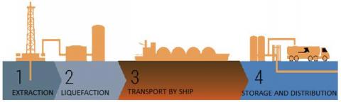
Natural gas in Italy is essentially imported in gaseous form through pipelines and, in liquid form, through capacious tanks housed in the LNG carriers (see Figure 1).
Figure 1. LNG extraction, transport, storage and distribution
Figure 2. Road and Rail LNG transport
LNG can be transported on road with Trucks, Semi-trailers or Isotank and by rail with Isotank (see Figure 2). Containerized vessels (Isotank) come transported by rail to a freight village, where they are transferred to semi-trailers, for the last part of the journey to the end users. Semi-trailers both with fixed tank and for transporting Isotank are widely used due to their large load capacity.
The load capacity of the transport units used for the distribution of liquid methane is between 8 and 30 t. A typical semi-trailer tank has capacity from 51,000 to 56,000 liters. Payloads vary depending on the required configuration. However, international transport has the total mass of vehicles limited to 40 t. To compensate for volume variations due to small temperature variations, the filling level shall always not exceed 95% of the volume of the tank when the temperature of the liquid corresponds to the set pressure of the safety valve. Tanks used to transport liquefied natural gas operate at relatively low operating pressures. Typical operating pressures vary between 3 and 7 barg. Typical safety valve opening values are 7 and 9 barg. Holding time is the maximum time for which LNG is stored in the liquid phase inside the tank before the maximum allowable working pressure is reached (MAWP). Typical holding time values are (with vehicle loaded at rest): 7 days for tanks with MAWP equal to 3 bar and 21 days for tanks with MAWP equal to 7 bar. LNG is a liquid in phase equilibrium and this physical condition is not stable. This implies that the product in its liquid form tends to gasify to return to its state of gas to atmospheric conditions. To slow down the phenomenon cryogenic tanks are at the forefront of technology to obtain the best thermal insulation. Thermal insulation is achieved by creating double-walled (concentric) tanks, with high vacuum and an insulating material (perlite) between the two. The inner wall is always made of Stainless Steel 304 (design temperature -196℃). The outer wall can be made of carbon steel or stainless steel.
LNG has the typical characteristics of a flammable substance, with the propensity to ignite and possibly explode in certain concentrations by volume with air. The main safety risks associated with the use of LNG are:
Flammability: it burns under the correct air/fuel ratio and ignition condition
Explosiveness: it can form explosive atmospheres
Eye and skin contact: being a cryogenic fluid it can cause burns and cold injuries
Asphyxiation: it can suppress oxygen indoors.
In case of accidental release, the generated vapors behave like a dense cloud until the temperature of the cloud rises by mixing with the air. Methane is lighter than air at temperatures above -110℃, so once heated above this temperature, being lighter than air, vapors can quickly disperse into the atmosphere, especially in a non-confined environment. Small LNG spills quickly gasify, larger spills of LNG remain on the ground and evaporate. The evaporation intensity depends on the substrate, temperature and area covered by the spill. The substrate eventually cools, reducing evaporation. In case of LNG leaks, due to evaporation, water particles (moisture) in the air freeze and a white cloud is formed. The leak cools the surrounding area and moves oxygen, creating a risk of freezing and anoxia. The gas itself is invisible, however the visible cloud gives an idea of the size and direction of gas loss.
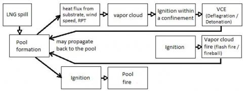
Significant physical phenomena related to the use of LNG are: flammability, explosiveness, Roll-over, Rapid Phase Transition (RPT), Boiling Liquid Expanding Vapor Explosion (BLEVE), Fireball (see Figure 3) [2].
Figure 3. Possible scenarios following LNG spills
4.1 Flammability
A cloud of LNG vapors is potentially subject to ignition when the concentration in air is within the flammability limits:
LFL (Lower Flammability Level): 5% in volume
UFL (Upper Flammability Level): 15% in volume
Within these limits, a cloud of LNG vapors and air, in the presence of triggers, can ignite giving rise to:
Flash-fire: rapid combustion of vapor clouds, non-explosive, developed in an unconfined space. Is the most frequent scenario;
Jet-fire: vapor jet fires produced as a result of leaks in pressurized tanks or pipes. The LNG jet that escapes into the atmosphere evaporates and expands simultaneously, mixing with air (fire darts);
Pool-fire: fire of pools following accidental LNG spillage.
The emissive power of LNG flames is particularly high (about 200 kW/m2), which is why it is necessary to monitor areas potentially susceptible to accidental releases and provide for the appropriate distancing of equipment to avoid damage to people and property. The NFPA 59A standard requires that a safety distance for unprotected people is set at a radiant heat flux of 5 kW/m2.
4.2 Explosiveness
The transport and use of considerable quantities of liquefied natural gas leads to concern over the possibility of a large spill and the consequent formation and ignition of an unconfined combustible cloud (predominantly methane and air). While such a cloud can burn, it is not clear whether detonation can occur under these unconfined conditions.
In non-confined environments, unconfined vapor cloud explosion (UVCE) conditions can usually be found in the presence of an amount of LNG compounds of the order of 15%, generating minimal overpressure within the cloud, with low-speed ignition propagation. A shared result is that unconfined explosions are possible rarely and only for high quantities and high ignition energies.
In highly congested or confined environments, on the other hand, explosions with higher pressures can be easily expected even for compositions with less than 15%, resulting in scenarios with more serious effects (VCE, Vapor Cloud Explosion). A VCE produces two damaging properties: pressure waves and thermal effects.
4.3 Roll over
It is possible that two layered cells are formed in LNG storage tanks, generally because of inadequate mixing of fresh LNG with an LNG bottom of different densities, as a result of filling operations. The lower layer, due to the ingress of heat into the tank, heats up to such an extent that its density is close to that of the upper layer.
Convection movements inside the tank can cause a rupture of the stratification in a very short time resulting in a rapid increase in the rate of evaporation from the tank itself and emission of large amounts of gas.
Risk mitigation actions can be mechanical mixing and loading tanks from top to down.
4.4 Rapid Phase Transition (RPT)
It is an explosive phenomenon without combustion because the increase in LNG temperature, for example due to contact with a liquid at different temperatures (such as water), is so rapid as to lead to rapid evaporation with the production of vapor at explosive speed.
4.5 BLEVE (boiling liquid expanding vapor explosion) and Fireball
The BLEVE (boiling liquid expanding vapor explosion) can occur with almost any liquid contained in a closed vessel, at a temperature well above its boiling point at atmospheric pressure. If the vessel fails, the vapor will expand and the superheated liquid will undergo a quick flash vaporization; the associated sudden increase in volume will originate an overpressure wave, that is an explosion.
The heat transfer coefficients for the liquid phase are an order of magnitude higher than those of the gas phase. Therefore, in a tank surrounded by flames, the metal wall will be "cooled" in the part in contact with the liquid phase, while in the part in contact with the gaseous phase there will be the most severe conditions, especially for the points directly in contact with the flame. Here generally occurs the structural failure and consequently the breakage of the tank shell, since the metal sheet is significantly weakened by the high temperatures induced and by the pressure increase connected with the heating of the contents.
This explosion can occur with any liquid, be it flammable or not, but if flammable then it will be followed by a fireball. The fireball is a fire, burning sufficiently rapidly for the burning mass to rise into the air as a cloud or ball. A fireball takes place when a flammable liquid, gas or dust cloud is suddenly released and has limited mixing with air prior to ignition. The couple BLEVE - Fireball can occur both in fixed plants and in LNG transportation by rail or road.
For the study of this type of scenarios, the Sigem-Simma software supplied by the Italian Fire and Rescue Service and developed by TEMA S.p.A. can be used. It consists of a set of calculation programs designed for the simulation of accidents for the purpose of applying and verifying the emergency plan [3].
Figure 4. Damage areas calculated with Sigem-Simma
Regarding the BLEVE and subsequent FIREBALL scenario for a tank containing 50 m3 of LNG (equal to about 23 t, which we consider totally involved in the accident), with the use of the software Sigem-Simma, setting the calculations for methane, the following circular form planning zones (with center in the place where the tank is located) are obtained (see Figure 4):
area of high lethality, (within the diameter of the Fireball) up to a distance of 178.5 m
area of possible lethality, up to a distance of 204,5 m for a thermal radiation intensity of 350.0 kJ/sqm
irreversible injuries area, up to a distance of 320.0 m for a thermal radiation intensity of 200,0 kJ/sqm
reversible injuries area: up to a distance of 425.0 m for a thermal radiation intensity of 125.0 kJ/sqm.
In Europe, there have been several road transport accidents, but fortunately there have been very few with serious consequences. Below we list three of the major ones:
Tivissa (Spain): On June 2002, a tanker truck carrying about 20 t of LNG overturned. A fire ensued, enveloping the tank. The tank burst 20 min after the start of the incident. The driver was killed and two people were burned about 200 m from the truck.
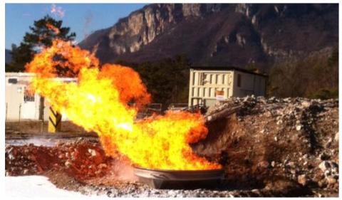
Zarzalico (Spain): On October 2011, a road accident of a tanker transporting about 20 t of LNG originated a fire (see Figure 5) and, finally, the BLEVE of the tank. The accidental sequence was fire, LNG release, further safety valves release, flames impingement on vessel unprotected wall, vessel failure, explosion and fireball [4]. Calculations showed that the resulting fireball would have had a diameter of 133 m, located 100 m above ground, and lasted 9,4 s. This and Tivissa's were non-vacuum insulated tanks. In 2013 Spain banned this kind of tank, as other countries did
Telemark (Norway): On October 2015, a road tanker drove off the road and overturned in steep terrain, stopping when arrested by a large tree penetrating the window of the driver’s cabin. The full LNG tank came loose and rolled further down the slope to flat terrain 30 m from the road. The outer shell was damaged against rocks, thus puncturing the vacuum protection. The tank finished upside down, i.e., the pressure relief valve would release liquid if the PSV set point pressure was reached, i.e. 6 barg. The complete operation, during which approximately 30 t of LNG were flared, lasted 46 h, involving several cooperating companies and emergency response organizations [5].
Based on their experience, the Italian firefighters have identified as a critical aspect the fact that the tanks on trucks and semi-trailers for the transport of LNG are certainly resistant to shocks and possible radiation due to an external fire, but could in any case be seriously damaged by a collision with a sharp object (for example: guardrail poles, sharp rocks). In the best-case scenario, such an event would easily lead to the loss of thermal insulation due to damage to the external tank. Up to now this aspect has not been sufficiently explored with experimental tests.
Figure 5. The accident in Zarzalico (Spain) in 2011
6.1 Transport units safety features
LNG transport vehicles have common and standardized safety features. All transport units are equipped with safety valves to prevent excessive pressure inside the tank. The exhaust pipes, which can be opened to discharge condensed liquid into the tank, come out from the top and back of the transport unit.
The tanks of the transport unit are equipped with a liquid level indicator indicating the level of the liquid in volume percentage. The tanks are also equipped with pressure gauges that indicate the pressure in the tank. The construction of the tank provides a high level of passive protection from fire.
The interception valve closest to the tank is pneumatically controlled. All interception valves are closed during transport. Connector joints on the tank and hoses are standard.
6.2 Tests carried out by the Italian Firefighters
The Italian firefighters carried out a series of tests on the behavior of LNG, even in the event of a fire. The tests took place in 2018, at the Trento training center in northern Italy. The experimental tests carried out were the following:
extinguishing agents were used on LNG pool fires for vapor dispersion control and pool fire suppression (see Figures 6-7), good results were obtained only with high expansion foams (1:500) at high flow rates (10 liters/min), as proven in previous research [6] or with powders. Foam application provided an initial negative effect by increasing the vaporization, but the effect was minimized as the fire was gradually suppressed.
the danger of using water to extinguish LNG pool fires has been verified and confirmed, LNG floats on water and evaporates faster with higher flames.
outdoor LNG spill experimental works have been conducted to evaluate the effectiveness of water curtain application in dispersing LNG vapors (see Figure 8), which has been verified, as proven in previous research [6]. The reduction of the concentration of LNG vapors in the air was verified using portable explosimeters.
an emergency transfer of LNG from one tanker to another was simulated, using the elements and pipes shown in the diagram in Figure 9. The diagram includes the damaged tank, an empty tank into which the LNG is to be transferred, a cryogenic skid pump, an evaporator and two torches. The skid pump includes by-pass valves, connections and temperature and pressure control systems. Initially, if necessary, the pressure in the damaged tank is reduced by sending part of the vapor phase to the torch. Then the liquid phase is recirculated between the pump and the damaged tank, to cool the pipes and the pump, to the correct operating temperature. Once this is done, the LNG is transferred by the skid pump into the new tank, which also has the vapor phase outlet connected to a torch. The operation is carried out by constantly monitoring the pressure in the two tanks and trying to transfer the largest possible quantity of liquid phase, because small quantities of LNG in a tank evaporate more quickly. There is also an evaporator (consisting of a bundle of finned tubing) to dispose of the liquid phase of the damaged tank (if necessary) by first evaporating it and then burning it in a torch.
the controlled disposal of LNG contained in a tank was simulated by burning it in a special torch, which is equipped with a coil, placed before the terminal part, to completely vaporize the liquid phase, in order to burn it. This torch can be an alternative to the evaporator mentioned in the previous point, but it’s still in the experimental stage.
Figure 6. Test with LNG pool fire
Figure 7. Extinguishing the pool fire with foam
Figure 8. Application of water spray to disperse LNG vapors
Figure 9. Scheme for LNG emergency transfer
6.3 Solutions to prevent LNG transport emergencies
In Europe LNG is among the dangerous goods, so its transport by road is regulated by the International Agreement for the Transport of Dangerous Goods by Road (ADR), which establishes the requirements for: structure of vehicles and tanks, marking of vehicles, vehicle crews, equipment and operation. The ADR agreement is regularly updated every two years, to take into account technological development and the new needs of the world of transport. The agreement also specifies minimum fire protection and security measures. In addition to the provisions of the ADR agreement, the International Group of Liquified Natural Gas Importers (GIIGNL) [7] provides some safety recommendations for the transport of LNG by road:
use of a double-walled vacuum-insulated tankers (when not mandatory).
Equipping the road tanker with an emergency shutdown (ESD) system that closes isolation valves and shuts down the LNG transfer pump (when applicable).
use of isolation valves for liquid and gas lines on the road tanker which are controlled by fail-safe actuators and an excess flow valve (EFV) on the liquid line.
use of an inhibit system which maintains the closure of the product transfer lines when the road tanker brakes are not applied, to prevent the failure of a transfer line if the road tanker moves.
equipping the road tanker transfer control system with a "deadman button”, to keep the operator in place during the transfer process.
Finally, thanks to the knowledge gained by the Italian firefighters in dealing with this type of emergency, it is possible to identify some additional safety measures:
vehicle should be equipped with a certain number of dry powder fire extinguishers, higher than the minimum required by the ADR agreement and with satellite positioning system.
each transport trip must include at least two drivers with sufficient driving experience (a few years) and the continuous driving time cannot be more than six hours; the drivers must be trained with the knowledge of LNG transport to effectively manage dangerous conditions.
transportation routes must be designated to facilitate traffic and rescue, also taking into account the weather conditions; in mountainous terrain, access should be prohibited on road not suitable for dangerous goods transport.
the scenarios with accidents involving transport of this type must be foreseen in the local civil protection plans, considering: vehicles, road and weather conditions, communications, command, operational coordination, traffic control, identification and quantification of the dangerous substance, waste disposal, evacuation, alert and eventual population evacuation, rescue and firefighting, medical assistance and environmental tests.
it is necessary to carry out coordination and joint exercises or seminars, listen to opinions of technicians and experts to improve and revise emergency plans and vehicles requirements to make them more suitable to actual needs.
6.4 Procedures to manage LNG transport emergencies
The Italian Fire and Rescue Service has developed intervention procedures to deal with LNG transport accidents, based on the experience and research carried out. The basic steps of the procedures are:
Alert emergency services and police
Notify the supplier
Secure an area 300 m around the accident
Specific measures of the situation.
The first three steps (warning and protection) apply to all situations. The last depends on the scenario. The Italian Fire and Rescue Service has identified five possible scenarios:
The transport unit has rolled or is standing and is judged intact.
The transport unit is rolled or standing and there is an established leak of methane gas but not liquid methane.
The transport unit is rolled or standing and loses liquid methane.
Transport unit loses liquid and/or gaseous methane that is burning.
External fire affecting the transport unit.
Specific procedural decisions should be made collectively by the incident commander, supplier and driver. The incident commander always makes decisions on the spot. Factors influencing the decision may include visibility, light, wind (direction and speed), rain, air temperature, topography, vegetation, terrain, human activity, possible sources of ignition, and on-site expertise and experience. Common aspects of all procedures are to stop all engines and remove all ignition sources except the damaged truck from the secured area and allow only authorized personnel to access it. In case of gas leaks, the actions to be taken are: try to stop them, consider the wind direction and use water spray curtain for reducing the concentration of LNG vapor clouds. If the LNG vapors have ignited, first assess whether the leak can be stopped by cutting off the liquid supply, then avoid spraying water on the leak, as water produces heat and increases evaporation, which in turn can increase the intensity of the fire. If it is necessary to empty the transport unit, the procedure must be determined jointly by the incident commander and the LNG supplier and a valid piping diagram to be adopted is the one shown in Figure 9.
7.1 Major accidents
Over the last years there have been several accidents in the factories that deal with LNG. Some of them have had serious consequences and have been studied to draw lessons learned. Below we list some major accidents in which there have been victims and/or injuries and the related causes.
Arzew, Algeria, 1977 (1 dead): LNG spray caused by catastrophic rupture of the upper valve body (liquid phase) of an underground tank being loaded. Cause: valve in aluminum not suitable for low temperatures.
Mexico City, Mexico, 1996 (6 dead – 30 injured): liquid hydrocarbon leak, fire and domino effect, with three explosions. Cause: human error during maintenance.
Longford, Australia, 1998 (2 died – 8 injured): failure of a hot oil pump, consequent chilling of vessels, re-introduction of hot oil into the heat exchanger caused rupture, gas release and explosion. Cause: wrong procedure and inadequate training.
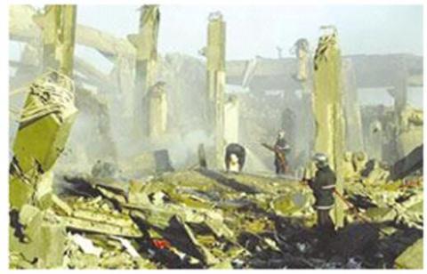
Figure 10. The accident in Skikda (Algeria) in 2004
Skikda, Algeria, 2004 (27 dead – 74 injured): release of LNG from loss of containment in a process section, sucked from air intakes of a boiler and exploded in a confined environment, with domino effect (see Figure 10). Cause: poor maintenance and poor general condition [8].
Plymouth, USA, 2014 (5 injured): explosion on a portion of the facility’s LNG purification and regeneration system during start up. Cause: substandard purge of the system.
7.2 Lessons learned from accidents
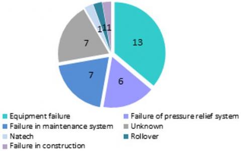
Among the various lessons learned from the analysis of the most serious accidents that occurred in recent years in plants that treat LNG [9], the most important are the following (see Figures 11-12):
Importance of the correct application of the European Directive 2012/18/EU (Seveso III) and subsequent amendments.
Use of materials suitable for cryogenic temperatures.
Importance of HAZOP studies or any other procedures for the identification of hazards in gas plants.
Make sure that gas supply lines contain nothing but gas before the equipment they feed is started.
Pay attention to loading and unloading of LNG (see Figure 11).
Importance of good maintenance, Standard Operating Procedures (SOP) and training (see Figure 12).
Awareness of cryogenic impacts.
Importance of alarm systems and emergency management.
Figure 11. Primary causes of 36 LNG incidents [9]
Figure 12. 36 LNG incidents studied by type of activity [9]
7.3 Safety measures in LNG plants
The sections of the LNG gas storage plant are schematized as follows:
transfer area between LNG carrier and cryogenic tanks;
storage area (cryogenic tanks);
transfer area to tank vehicles, ISO containers or rail tankers;
vaporization area;
BOG management area (BOG stands for boil-off gas, that is the gas produced by the evaporation of LNG due to the heat transmitted from the outside of the tank to the stored product).
Directive 2012/18/EU and subsequent amendments, implemented in Italy by Legislative Decree no. 105/2015 (so-called Seveso Decree), applies to plants in which dangerous substances are present in quantities equal to or greater than certain thresholds, which consequently differentiate general and specific obligations for both the plant managers and the authorities of the Member States.
In the specific case of an establishment used for the reception, storage and regasification of LNG, Liquefied Natural Gas falls within the category “18. Flammable liquefied gases, category 1 or 2 (including LPG), and natural gas”, whose thresholds, listed in Annex I part 2 of the directive are:
lower threshold plants: from 50 to 200 t;
upper threshold plants: over 200 t.
The Italian Fire and Rescue Service has also issued, with the circular letter of 12 September 2018, n. 12112, a technical fire prevention guide for the analysis of LNG gas storage plant projects with a capacity exceeding 50 t.
In Europe, the reference for the design of LNG storage systems, with capacities between 5 t and 200 t, is the EN 13645:2001 standard, which provides indications on the design of the supply and handling lines of the product.
Safety features of LNG facilities are an inherent part of each design. The main safety measures present in the plants that treat LNG are [10]:
use of materials suitable for cryogenic temperatures (as required by the standard ISO EN 16903);
cooling of LNG transfer lines and pumps before use;
tanks types are of three types: single containment, double containment and full containment. The single containment type consists of a single container of suitable material, surrounded by a layer of insulation. The double containment is made with two containers, one inside the other, where the internal container is built with a material suitable for containing LNG, while the second is built with material that is unable to contain LNG for a long time. The insulation is interposed between the two containers. The total containment, on the other hand, has an external containment built in material suitable for containing any LNG spills in the liquid phase from the internal container. To evaluate the thermal impacts on the tanks due to fires, it is therefore necessary to consider the insulation. The technical standards (EN 1473) require that those of the first and second types are equipped with containment basins. They should be scaled, as a precaution to contain leakage up to 110% of the tank capacity and paved and sloped in such a way as to avoid, in the event of release, the permanence of LNG under the tank itself;
detection systems: fire detection systems, designed to detect smoke, flames and heat, and also the cold, near the dangerous elements of the system, but also systems designed to detect the presence of gas (see Figure 13). The systems are associated with signaling and alarm systems and with the activation of blocking systems or extinguishing systems. The electrical systems must be suitable for hazardous locations with the presence of explosive atmospheres (ATEX);
overpressure protection (pressure controllers and relief valves);
an Emergency System that mitigates any Loss of Containment (LOC), such as an Emergency Depressuring System (EDS), an Emergency Shutdown System (ESD) and a fire protection system that automatically activates fire suppressants;
active and passive fire protection (internal fire team, preinstalled monitors, trolley mounted fire extinguishers, fireproofing barriers and coatings);
trained operators always present; their response includes making emergency notifications to firefighters; closed-circuit TV monitoring and strict site access controls are also necessary;
appropriate PPE, LNG specific and approved tools and calibrated portable gas detectors for all plant operators and drivers.
Figure 13. Safety measures for LNG plants: at the top left a gas detector, right, pumps of a fire-fighting system, bottom left and right systems for cooling tanks and loading area
The extinguishing agents normally used in LNG plants are water, foams, and powders. Water is used to protect areas or to cool tanks near the areas affected by the fire, but also to protect people from exposure to a fire (see Figure 13). The foam, on the other hand, can be used to cover any pools of LNG following releases, to avoid triggering and reduce evaporation. Wheeled powder fire extinguishers have proven effective in extinguishing ponds of LNG.
Transfer lines and pumps must be cooled before sending the LNG to avoid overpressure problems that would make transfer difficult. Due to the specific physical characteristics of LNG, it is necessary to avoid that the rise in temperatures generates strong pressure gradients in the connection pipes and therefore the simple sectioning of the liquid phase connection pipes must also be avoided.
The transfer to LNG transport vehicles normally takes place in specific loading and unloading platforms, through suitable connection systems, distinct for the two phases of the system, equipped with shut-off valves, emergency shutdown buttons, break-away coupling on the LNG transfer lines, which automatically and without delay closes internal isolation valves in case of tension on the transfer line, as well as an inertization and drainage system on the pipes. Platforms should also be equipped with an impounding basin for conveying LNG spills away from the plant, weight bridge and flow rate meter to prevent overfilling of the road tankers and entry/exit roadway barriers and vehicle impact to protect plant and equipment.
The proper functioning of LNG storage facilities is normally characterized by the minimization of emissions into the atmosphere, through the recovery and use of the BOG produced, both in ordinary and emergency conditions, by means of a release system to which the pressure control valves, tank safety valves and system thermal expansion and air release valves. The torch release system is also used for the depressurization of the system for maintenance interventions.
As general organizational measures for the plant, it is necessary to develop emergency plans and verify them with periodic exercises and to have a valid maintenance management system and an incident monitoring system.
8.1 Distribution of natural gas in Italy
Natural gas (in the gaseous state) is transported in piping networks and it is nevertheless interesting to have an idea of the risk of accidents connected to them.
Although LNG imports by ship will grow in the future, about 80% of the Italian demand for NG is still fueled by imported gas, which is taken over abroad and conveyed to Italy by means of large international gas pipelines. NG transportation and distribution networks are therefore capillary infrastructures and intimately connected with the other portions lying on the European territory. This makes the gas transmission network an example of EU “critical infrastructures”, defined in the Green Paper COM (2005) 576 final [11], such as physical and information technology infrastructures, networks, services and goods whose damage or destruction would have serious repercussions on the health, safety and economic or social well-being of citizens of the Member States. The design criteria adopted for the networks are based on national sector regulations, in turn based on international standards and on consolidated experience and are aimed at obtaining a high degree of safety, plant reliability and operational efficiency. The Italian technical rule in force for the design, construction, testing, operation and surveillance of NG transport and distribution systems is the ministerial decree April 17, 2008. The decree was issued to guarantee safety, including fire safety aspects and the possibility of interconnection of NG transport and distribution systems, gas compression and decompression systems as well as transport systems to industrial activities. Once at the border, the transport and dispatching of NG is carried out, and subsequent distribution to end customers.
The transport of NG, also called primary distribution, normally takes place with high pressure networks (> 0.5 MPa), starting from the main (or backbone) methane pipelines. Dispatching of NG, also known as secondary distribution, is carried out locally via medium and low pressure networks (< 0.5 Mpa). The transport of NG via pipelines in Italy takes place with a network of over 30,000 km managed by SNAM company.
8.2 Historical analysis and emergency scenarios
Examining the European data, in Table 2 are shown the results of studies carried out in 1996 by Montiel et al. [12] where the incidental data relating to NG were collected with the MHIDAS and ESTRELL databases, updated through the MARS database (“Major Accident Reporting System”), created by the European Union with the Seveso Directive, which show how NG-related accidents can be divided according to their sector of use. This shows that about 70% of accidents occurred during the transport phases, whether by road, rail, ship or pipeline.
Table 2. NG related accidents [12]
|
Origin of the accident |
Events |
Percentage |
|
Transport |
134 |
69% |
|
Process plants |
33 |
17% |
|
Storage |
17 |
9% |
|
Domestic / commercial |
9 |
5% |
|
Total |
193 |
100% |
Table 3. NG transport accidents [12]
|
Origin of the transport accident |
Events |
Percentage on transport |
Percentage on total |
|
Pipelines |
129 |
96.3% |
66.5% |
|
Pumping/compression |
2 |
1.5% |
1.0% |
|
Rail tankers |
2 |
1.5% |
1.0% |
|
Substations |
1 |
0.7% |
0.5% |
|
Total |
134 |
100% |
69% |
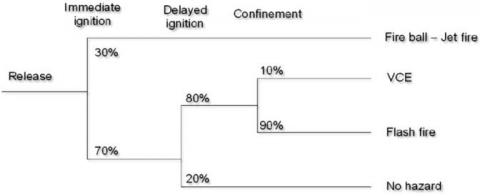
Figure 14. Percentages of occurrence of events and scenarios for release of NG from a pipeline [13]
Regarding the more specific cause of the generic transport sector, Table 3 shows the distribution of the major incidental contributions. The data clearly show that the highest frequency of accidents involved the transport pipelines (about 67% of cases).
The pipes are normally placed in the ground, and in theory, outside the influence of external factors acting on the surface. In any case, they are subject to various natural activities and phenomena that can lead, not necessarily immediately, to an accidental event, which in our case will be represented by a rupture and consequent release of NG. Studies carried out by Muhlbauer [13], for the transport pipelines of NG, prove the results shown in Figure 14, with an indication of the probability of occurrence to be assigned to each of events and scenario for the release of NG from a pipeline. The graph shows that, following a release, the probability of a flash fire scenario is 50%, that of a jet fire scenario is 30%, that of a VCE is about 6% and that of the simple dispersion of gas in the air is about 14%.
The main danger for the transport of natural gas is the rupture of the pipe or valve and the consequent release of gas into the environment. Depending on the environmental conditions present around the release point, the escape of gas, by its nature extremely flammable, can give rise to a series of chemical-physical phenomena (fires and explosions), which can they can cause harm to people's health and – in the most serious form – can cause the death of the population living in the perimeter of the infrastructure.
Two recent accidents with deaths and injuries caused by the release of NG from the distribution network were those that occurred in San Bruno (California) in 2011 and in the Merrimack Valley (Massachusetts) in 2018.
The data examined shows us that although pipeline transport is considered to be one of the safest methods for long-haul transport, the number of accidents is often the same as that of refining plants.
8.3 Solutions for gas pipeline networks safety
The continuity and safety of gas transport must be guaranteed by the transport company, through the implementation of accident prevention systems and the management of any emergency, where "emergency" is any event that occurs in the operation of the transport system, that may be detrimental to the safety of persons, property and property of third parties, for the environment in general, or for the safety of the plant and the continuity of transport. These systems must be implemented through the definition of company procedures and provisions that allow to assign roles and responsibilities for the management of safety aspects, ensuring adequate training of personnel, the adoption of appropriate measures for operation and maintenance of plants and pipelines and the management of any emergency situations. The gas distributing company must have free access to its pipelines and installations with the personnel and means necessary for monitoring, operation and maintenance. In addition, the gas company must affix special signs along the route of the pipeline, in order to allow its easy identification and for the safe execution of works near them.
In particular, in addition to compliance with design standards, reducing the risk of accidents in distribution networks already built requires [14]:
performing a risk analysis, which aims at finding out the potential accidents and their consequences
preventing and promptly detecting gas leakages, with gas detection survey (continuous sampling of the atmosphere at ground level), vegetation survey (to detect unusual indications in vegetation due to the gas), pressure drop test, bubble leakage test, ultrasonic leakage test (looking for ultrasonic energy produced by the gas leak)
training staff so that they can intervene quickly and effectively on breakdowns
ensuring that the gas distribution company carries out continuous monitoring of the network, e.g. using sensors and IoT technologies
collecting all data on accidents and "near misses".
The LNG industry is expected to grow dramatically as the demand for natural gas increases worldwide. The potential hazards imposed from an accidental release of LNG promoted the continued study on the safety and security. Despite advances in safety knowledge, LNG remains a high hazard substance and adequate control is only partially achieved through improvements in technology and standards. A large portion of prevention and protection measures depend on the proper design and execution of safety procedures, a well-functioning safety management system, and a good risk assessment.
The Italian Fire and Rescue Service (Italian firefighters) conducted research and outdoor LNG spill experimental tests. The tests confirmed results obtained in other studies. Also, a training program and information exchange with the main transport and distribution companies has started.
Even for the transport of NG in pipelines, although it is considered one of the most consolidated and safe methods for long-range transport, the case history of accidents is still worthy of attention.
There is the need to share data and lessons learned on accidents that occurred and to carry out further research. The importance of carrying out common training between firefighters and LNG companies has emerged.
|
BLEVE |
Boiling Liquid Expanding Vapor Explosion |
|
BOG |
Boil Off Gas |
|
CNG |
Compressed Natural Gas |
|
EFV |
Excess Flow Valve |
|
EDS |
Emergency Depressuring System |
|
ESD |
Emergency Shutdown System |
|
HAZOP |
Hazards and Operability |
|
LNG |
Liquefied Natural Gas |
|
LOC |
Loss Of Containment |
|
LFL |
Lower Flammability Level |
|
NG |
Natural Gas |
|
PPE |
Personal Protective Equipment |
|
RPT |
Rapid Phase Transition |
|
UFL |
Upper Flammability Level |
|
UVCE |
Unconfined Vapor Cloud Explosion |
|
VCE |
Vapor Cloud Explosion |
[1] International Gas Union. https://igu.org/, accessed on Jan. 3, 2020
[2] Ikealumba, W., Wu, H. (2014). Some recent advances in liquefied natural gas (LNG) production, spill, dispersion, and safety. Energy & Fuels, 28(6): 3556-3586. https://doi.org/10.1021/ef500626u
[3] Italian Fire and Rescue Service (Italian firefighters). https://www.vigilfuoco.it/, accessed on Jan. 3, 2020.
[4] Planasa, E., Pastora, E., Casala, J., Bonilla, J.M. (2015). Analysis of the boiling liquid expanding vapor explosion of a liquefied natural gas road tanker: the Zarzalico accident. Journal of Loss Prevention in the Process Industries, 34(4): 127-138. https://doi.org/10.1016/j.jlp.2015.01.026
[5] Metallinou, M.M. (2019). LNG as a new hazard; learning processes in Norwegian fire brigades. Safety. 5(1): 11. https://doi.org/10.3390/safety5010011
[6] Kim, B.K., Ruíz, R., Zhang, B., Nayak, S.G., Mentzer R., Mannan M., O’Connor M. (2012). Recent progress in LNG safety and spill emergency response research. Proceedings of Hazards XXIII, Institution of Chemical Engineers, 12-15.
[7] International Group of Liquefied Natural Gas Importers. https://giignl.org/, accessed on Jan. 3, 2020
[8] Ouddai, R., Chabane, H., Boughaba, A., Frah, M. (2012). The Skikda LNG accident: Losses, lessons learned and safety climate assessment. International Journal of Global Energy Issues. 35(6): 518-533. https://doi.org/10.1504/IJGEI.2012.051691
[9] Study of the Joint Research Centre of the European Commission on 36 LNG accidents on land-based sites, MAHBullettin, No. 13, December 2018. https://minerva.jrc.ec.europa.eu/en/minerva, accessed on Jan. 3, 2020.
[10] Mokhatab, S., Mak, J.Y., Valappil, J.V., Wood, D.A. (2014). Handbook of Liquefied Natural Gas. Gulf Professional Publishing, Elsevier Inc. https://doi.org/10.1016/C2011-0-07476-8
[11] Commission of the European Communities. Green Paper on a European programme for critical infrastructure protection. COM(2005) 576 final. Brussels, 17.11.2005. https://eur-lex.europa.eu/legal-content/EN/TXT/?uri=celex:52005DC0576, accessed on Jan. 3, 2020.
[12] Montiel, H., Vilchez, J.A., Arnaldos, J., Casal, J. (1996). Historical analysis of accidents in the transportation of natural gas. Journal of Hazardous Materials, 51(1-3): 77-92. https://doi.org/10.1016/S0304-3894(96)01819-5
[13] Muhlbauer, W.K. (2004). Pipeline risk management manual (3rd ed.), Gulf Publishing Co. https://doi.org/10.1016/B978-0-7506-7579-6.X5000-6
[14] Bianchini, A., Donini, F., Guzzini, A., Pellegrini, M., Saccani, C. (2015). Natural gas pipelines distribution: Analysis of risk, design and maintenance to improve the safety performance. Proceedings of the XX Summer School ‘Francesco Turco’—Industrial Systems Engineering, Naples, Italy, 243-248.