Hatam Samaka* | Hussein Al-Bugharbee | Mohammed Al-Azawy
© 2020 IIETA. This article is published by IIETA and is licensed under the CC BY 4.0 license (http://creativecommons.org/licenses/by/4.0/).
OPEN ACCESS
The number of fatal and non-fatal pedestrian injuries, due to car accidents, has increased. For this reason, design of least possible harm cars (i.e. pedestrian friendly cars) has attracted the interest of many researchers and companies in order to reduce mortality and mitigate injuries. The use of friendly cars can also lead to the reduction of the expensive medical treatment costs for pedestrian injuries and consequently alleviates the financial burdens of the governments and insurance companies. In the sedan cars accidents, the common first pedestrian body part which experiences impact is the legs. In this research, a simulation study is conducted for investigating the effects of car bumper profile and plastic grille tilt angle on the severity of collision. LS-Dyna software is used to simulate, numerically investigate and analyze the mechanism of collision between a simulated leg and a vehicle bumper. In this simulation, three parameters are considered, impact line between pedestrian leg and car bumper, the height of the bumper relative to the knee, and the plastic grille tilt angle. The results of this study showed that the increase of impact line, increase of bumper height and decrease the plastic grille tilt angle alleviate the severity of pedestrians leg injuries.
pedestrian safety in car accidents, pedestrian friendly cars design, F.E legform impactor model, EEVC/WG17 regulation, sedan car design
Pedestrian accidents have been considered as a major cause of traffic induced fatalities and non-fatality injures. They still compose a huge social and economy burdens. In 2013, the Morbidity and Mortality Weekly Reports (MMWR) USA showed that the work losses costs and medical treatment for pedestrian fatal and non-fatal injuries are approximately 382.5 billion dollar [1]. In 2016, there was a high accident rate in the UK compared with USA and Japan. The recorded accidents reach 181,384 (1792 of them are death). In addition, 25% of these accidents were pedestrian and others are with motorcyclists [2]. In the 2018 report of the World Health Organization (WHO), it is stated that there are approximately 1.35 million people died all over the world due to the road traffic crashes [3]. Moreover, half of these accidents were with were pedestrians [4].
In 2018, the Institute for Traffic Accident Research and Data Analysis of Japan [ITARDA] reported that 37% of the traffic death in Japan was pedestrians [5]. In the USA, there are 6,283 pedestrian death cases were recorded by the National Highway Traffic Safety Administration (NHTSA) due to traffic crashes occurring on public roads in 2018 [6]. In 2019, an increase of 5% of pedestrians’ death was observed by Governors Highway Safety Association (GHSA) USA [7]. On the same year and in the UK, a 40% of pedestrians accidents deaths was recorded in comparison to those recorded in 2018 [8]. In Germany, the Germany Road Safety Report 2019 stated that 47% of the total road fatalities is recorded to pedestrians [9].
According to the statistics, the number of pedestrian injuries in road accidents is usually considerably higher than the number of deaths, as about 1.55 million people die, while another 60 million are injured [10].
Lower leg injuries are the highest among pedestrian accidents injuries, in the USA 43% of all injuries, 35% in Germany and 43% in Japan. And that the collision between the bumper and the lower leg leads to fractures in the shin bone and knee parts and rupture of the tissues connecting them [11].
In another study, the proportion of a pedestrian's leg injury is 41% from Abbreviated Injury Scale (AIS)2 of the pedestrian's body injuries. Therefore, studying and analyzing the mechanics of these injuries leads to a reduction in the severity of the injury [12].
It was reported in the studies [13-17] that the lower leg injuries forms the higher percentage of non-fatal injuries. For this reason, the design of the pedestrian friendly car has attracted the interest of researchers. These design studies focused on the collision behavior between the car engine cover with pedestrian head and the collision behavior of car bumper with pedestrian leg and to achieve effective mitigation of the injuries [18, 19].
It is reported by the German In-Depth Accident Study (GIDAS) that 75% of the total pedestrian non fatal injuries accidents is cause by sedan cars. In addition, 54% of these accidents occur at the front bumper of cars [18, 20, 21].
Few studies have focused on the shape of the car bumper and tilt angle. This research investigates the effect of the impact line, bumper height relative to knee and the grille tilt angle on the pedestrian leg injury severity. A numerical simulation is conducted using LS-Dyna software to analyze the collision mechanism.
The rest of the paper will be as follow: section two explains the present analysis methodology. Section three presents the tests and results of the current study. The section four illustrates the solution of the problem. Section 5 presents the discussion of the obtained results. Lastly, the conclusion is presented in section six.
This section illustrates the methodology used in this study. It aims to redesigning the car bumper profile to reduce the severity of pedestrian injury caused by accidents.
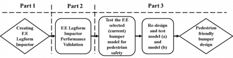
The present methodology has three parts; 1) creation of FE lower legform impactor, 2) legform impactor model validation, and 3) solution of the selected bumper model. The methodology flowchart is illustrated in Figure 1.
Figure 1. Methodology flowchart
2.1 Creation of finite element lower legform impactor
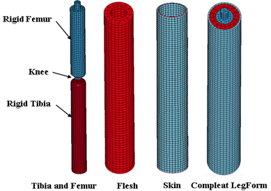
All leg model specifications are based on the EEVC/WG17 EURO Phase2 regulations. According to this regulation, the adult lower leg impactor model consists of three parts; tibia, femur and knee. These parts represented a leg bone covered by flesh and skin [19]. The FE impactor model is created as 3D by using Solidworks program, meshing and simulating by using LS-Dyna program. The three leg model parts are wrapped by CF-45, 25mm thickness ConforTM foam material representing the leg flesh. This foam layer covered by 5mm thickness from Neoprene Rubber representing the skin as shown in the Figure 2. The legform model mass is 13.4 kg.
Figure 2. The FE model used in the study
2.1.1 Tibia and femur
Steel tube tibia and femur are 70mm diameter with 1.5mm thickness connected together by Knee joint. Tibia and femur were modelled as a shell material. Total mass of femur and tibia are 8.6 kg and 4.8 kg and moment of inertia are 0.127 kg.m2 and 0.120 kg.m2 respectively .
2.1.2 Flesh and skin
Flesh is used in the real model made from CF-45 ConforTM foam material and skin from Neoprene Rubber [20]. The flesh was converted in LS-Dyna by a solid element with low density foam material type [38-*MAT_BLATZ_KO_FOAM] with mass density ρ=96.11 kg/m3 and skin was modelled by using solid element [107 viscoelastic material] with ρ=1100 kg/m3 .
2.1.3 The knee
In this study, knee group consists of two parts:
Two shell elastic parts connect the tibia to femur, see Figure 3. Material used in LS-Dyna for this part is PLASTIC_KINEMATIC that has ability to flex with 0.6mm thick and represents the main knee joint. This part is created to achieve a non-linear bending and linear translational deformation during shearing (dynamic and static tests) [19].
Four spring-dampers are used to observe the vibrations during impact (at dynamic tests) see Figure 3. To calculate spring constant K; the generated impact force (Eq. (1)) from dynamic impact test with 9 kg mass impactor and acceleration up to 150G in the legform (EEVC/WG) regulation is:
$F_{\max }=m a_{\max }$ (1)
where, Fmax is maximum force on the legform model, m is leg mass and amax is maximum acceleration of the legform model. Eq. (2) is used to calculate the required spring-damper constant for the knee at allowable maximum shearing displacement Smax = 6mm:
$K=\left(\frac{F}{S}\right)_{\max }=\frac{13243.5}{6}=2207.25 \mathrm{~N} / \mathrm{mm} \rightarrow K$
$=\frac{2207.25}{4}=551.81 \mathrm{~N} / \mathrm{mm}$ (2)
So the springs, used in simulation as shown in the Figure 3, have a constant [K= 551.81 N/mm] and the rotational damping constant was 2.5 N/mm .
Figure 3. Knee with spring-damper
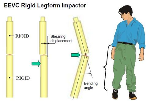
Figure 4. Major tests parameters (EEVC/WG17)
2.2 FE legform impactor performance validation
Two tests are required to evaluate the model's performance according to EEVC/WG17 regulation, static and dynamic tests. There are three parameters from the legform impactor required in the tests to evaluate the bumper performance for pedestrian protection, as shown in Figure 4. 1) Upper tibia acceleration 2) knee dynamic bending angle and 3) shearing displacement in the knee. The test velocity of the leg impactor was 40 km/h or 11.1 m/s according to EEVC/WG17 regulation and height from the ground is zero mm [21].
2.3 Current bumper model
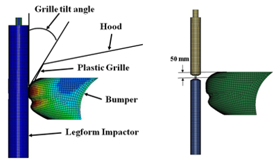
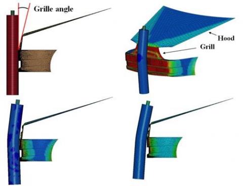
The Finite Element bumper model selected to use and analysis in this study (current bumper model) is shown in Figure 5. Grille tilt angle is the angle of inclination of the plastic grille edge from the vertical line of the leg impactor. The distance between the center of knee and upper bumper edge is 50mm. In this study, the used bumper car model does not subjected pedestrian protection regulations and the aim of the study is to redesign its profile shape with grille tilt angle of the car to mitigate the non-fatal injury of the pedestrian leg and knee at cars accidents.
(a) Current bumper model and grille tilt angle
(b) Knee and upper bumper edge
Figure 5. Analyzed bumper model
3.1 Legform impactor performance validations tests
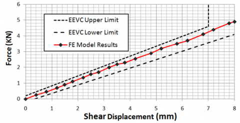
3.1.1 Static test (shearing displacement of knee)
This test was done to checking the behavior of the spring–dampers of the knee. The test results, shown in the Figure 6, explain that the generated shear displacement at knee within the regulation EEVC/WG limited range.
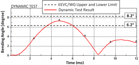
3.1.2 Dynamic test (bending test)
This test is performed to study the model's damping process during impact. Figure 7 shows the nonlinear variation of the force acting on the knee with nonlinear bending angle variation. This curve shows that the behavior of the model during bending test was within the limits of EEVC/WG17 regulation.
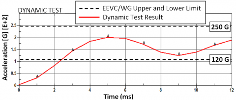
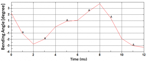
Figure 8 shows the generated Legform impactor three dynamic tests. These tests results show that; the Legform impactor model is within the limits of EEVC/WG17 and can be used in the bumper tests for friendly cars.
Figure 6. Static test result analyses
Figure 7. Dynamic test resultant analyses
(a) Acceleration test
(b) Bending angle
(c) Shear displacement
Figure 8. Legform impactor dynamic tests
3.2 Current bumper tests results
The simulation tests results of generated F.E legform impactor to the bumper (current bumper) shown in Figures 9.
(a) Acceleration test
(b) Bending angle
(c) Shear displacement
Figure 9. Current bumper model tests results
Summary of the tests results comparison with maximum acceptable EEVC/WG limits is shown in the Table 1. It can be seen that this current bumper model is not comply with the pedestrian protection specifications and will be injury severe at accidents.
Table 1. Current bumper model results with maximum acceptable EEVC/WG limits
|
Items |
EEVC/WG Maximum Limits |
Analyses Results |
|
Upper tibia acceleration (G) |
150 |
380 |
|
Knee shear displacement (mm) |
±6 |
15 |
|
Knee bending angle (deg) |
15 |
16 |
This current bumper can be developed by improving the pedestrian protection performance. This can be achieved through increasing the straight impact line between the bumper and legform impactor through changing the bumper profile and changing the impact location between the bumper and the legform impactor depending on the knee location. Furthermore, decreasing the grille tilt angle can also be very helpful.
4.1 First proposal: Bumper model (a)
The convex shape of the current bumper increases the curvature of the bending angle, so the proposed bumper model should have the least convex shape, in other words increasing the bumper impact straight line. Figure 10 shows the modified bumper (a) model with new profile.
Figure 10. The first proposed bumper model (a)
From the impact simulation tests; the leg model curvature is greater when the location of the knee is at the upper edge of the bumper, lead to a large curvature of the legform impactor model cannot prevents the femur bend as shown in the Figure 11.
Figure 11. First proposal-impact location model (a)
4.2 Second proposal model (b)
The position of the bumper will be changed in order to be higher than the knee line by increasing the plastic grille height (to increase the impact line) and decrease the grille angle to prevents the curvature (bending angle) of the legform impactor as shown in Figure 12.
Figure 12. Second proposal model (b)
Tests of upper tibia acceleration, knee dynamic bending angle and shearing displacement were carried out on the developed models (a) and (b). The results show that the distance 50mm between the centre of the knee and the edge of the bumper in the current model is a short distance that allows the upper leg to move forward freely at impact. The increase of the bending angle of leg leads to an increase in both the acceleration of the upper tibia to 380G and knee shear displacement to 15mm see Table 1. Finally, results are negative for pedestrian protection.
The implementation of the proposed solutions in model (a) and (b) leads to a high performance improvement, and decreases the upper tibia acceleration to about 220G and 130G respectively. In the bumper model (b), the upper end of bumper with plastic grille and hood is 220mm above line of knee as shown in Figure 12. This means collision is more concentrated to knee and femur. So, the upper tibia acceleration decreasing to 130G. The final upper tibia acceleration result in model (b) is within the EEVC/WG regulations maximum limits see Table 1 and Figure 13.
Figure 13. Upper tibia acceleration tests result
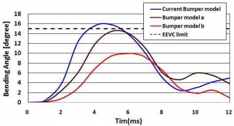
Increasing the bending angle leads to an increase in the damage and tearing of the connective tissues in the knee, i.e. the increase in the severity of the injury, so we are always keen to reduce to the lowest extent possible. In the current bumper model, bending angle is about 16 degree due to the absence of what prevents the femur to bending at moment of collision. This forms an angle greater than the permissible rang (EEVC limit) lead to severe injury. The modulation in model (a) reduces the bending angle to 14.7degree but it remains at critical limit. Decreasing the grille angle in model (b) is significantly improves performance, the bending angle reaches about 10 degrees, see Figure 14.
Figure 14. Bending angle test result
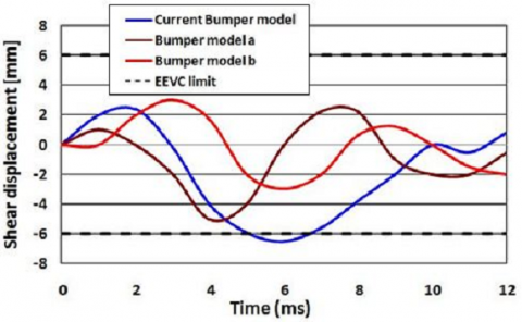
In the current bumper model the shear displacement is 6.5mm over the EEVC limits, modulation in model (a) reduced the shear distance to 5 mm, which is within acceptable but critical limits. Model (b) with a reduced grille angle, the femur movement will be limited and the banding angle is reduced, thus reducing the shear displacement to 3mm, see Figure 15.
Table 2 shows the summary of results of simulation tests for the three models used in the study, model (b) to improve the performance of current bumper.
Figure 15. Shearing displacement tests
Table 2. Current bumper model results with maximum acceptable EEVC/WG limits
|
Bumper model |
Max. upper tibia acceleration (G) |
Max. knee bending |
Max. shear displacement (mm) |
Impact line length (mm) |
|
Current bumper |
380 |
16 |
6.5 |
280 (Curve) |
|
Model a |
220 |
14.7 |
5 |
240 (Straight) |
|
Model b |
130 |
10 |
3 |
460 |
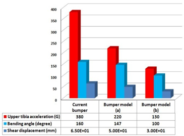
Figure 16 shows that the comparison of the simulation results for three bumpers are used in study. Bumper model (b) is the most matching the EEVC limits for all three factors, maximum tibia acceleration, maximum knee bending angle and maximum shear displacement. Thus, the performance of the bumper has been greatly improved and model (b) can use for pedestrian friendly cars.
Figure 16. Bumper models results comparison
The created legform impactor model can be used to test the modified bumpers with other studies for pedestrian protection as a ready-made model. The factors; bumper profile, bumper location to the knee and grille length with its tilt angle are influential factors at performance of bumper for pedestrian protection at cars accidents.
Simulation results of the current bumper show that it leads to a high non-fatal level of injuries in the pedestrian leg which makes the car non-friendly for pedestrian. On the other hand, the use of the model (b) leads to less possible level of non-fatal injuries according to EEVC/WG17 regulation.
The bumper performance of pedestrian protection can be improved by increasing the straight impact line between the bumper and pedestrian leg. In other words, the bumper with plastic grille tilt angle and hood (engine cover) can form a good system for pedestrian protection in accidents that reduces the severity of non-fatal injury in the pedestrian leg if they are modified as mentioned in this study. From this study, the same steps can be followed to redesign unfriendly cars bumpers as pedestrian-friendly car bumpers to reduce the severity of pedestrian leg injuries in accidents.
|
EEVC/WG17 |
European Enhanced Vehicle-Safety Committee Regulation |
|
MMWR |
Morbidity and Mortality Weekly Reports USA |
|
WHO |
World Health Organization |
|
ITARDA k |
Institute for Traffic Accident Research and Data Analysis of Japan |
|
NHTSA |
National Highway Traffic Safety Administration |
|
GHSA |
Governors Highway Safety Association |
|
GIDAS |
German In-Depth Accident Study |
|
CF-45 ConforTM |
Foam material |
|
K |
Spring constant N/mm |
|
S |
Shearing displacement mm |
|
Greek symbols |
|
|
ρ |
Density kg/m3 |
[1] Centres for Disease Control and Prevention. https://www.cdc.gov/injury/wisqars/cost/index.html, accessed on 20 June 2020.
[2] Jackson, L., Cracknell, R. (2018). Road accident casualties in Britain and the world. House of Commons Library: London, UK.
[3] WHO (2018). Global status report on road safety, USA.
[4] WHO (2013). Global status report on road safety: Supporting a decade of action. World Health Organization, USA.
[5] Matsui, Y., Oikawa, S. (2019). Situational characteristics of fatal pedestrian accidents involving vehicles traveling at low speeds in Japan. Traffic Injury Prevention, 20(sup1): S1-S6. https://doi.org/10.1080/15389588.2019.1587166
[6] NHTSA. https://www.nhtsa.gov/press-releases/roadway-fatalities-2018-fars, accessed on Sep 09, 2019.
[7] Car and Driver. https://www.caranddriver.com/news/a31136893/pedestrian-deaths-increase-2019/, accessed on Sep 09, 2019.
[8] Department for Transport. Reported road casualties in Great Britain: provisional results 2019. https://assets.publishing.service.gov.uk/government/uploads/system/uploads/attachment_data/file/904698/rrcgb-provisional-results-2019.pdf, accessed on Sep. 9 2019.
[9] Road safety annual report. https://www.itf-oecd.org/sites/default/files/germany-road-safety.pdf, accessed on Sept. 9, 2019.
[10] Babu, S.N., Tamilselvi, J. (2019). Generating road accident prediction set with road accident data analysis using enhanced expectation-maximization clustering algorithm and improved association rule mining. Journal Europeen des Systemes Automatises, 52(1): 57-63. https://doi.org/10.18280/jesa.520108
[11] Yang, S., Sun, Y., Qi, C. (2020). Performance assessment and optimal design of hybrid material bumper for pedestrian lower extremity protection. International Journal of Mechanical Sciences, 165: 105210. https://doi.org/10.1016/j.ijmecsci.2019.105210
[12] Tang, J., Zhou, Q., Nie, B., Hu, J. (2020). Obesity effects on pedestrian lower extremity injuries in vehicle-to-pedestrian impacts: A numerical investigation using human body models. Traffic Injury Prevention, 21(8): 569-574. https://doi.org/10.1080/15389588.2020.1821195
[13] Prentice, B.E., Prokop, D. (2015). Concepts of Transportation Economics. World Scientific Publishing Company, 1-332. https://doi.org/10.1142/9495
[14] Peng, Y., Han, Y., Chen, Y., Yang, J., Willinger, R. (2012). Assessment of the protective performance of hood using head FE model in car-to-pedestrian collisions. International Journal of Crashworthiness, 17(4): 415-423. https://doi.org/10.1080/13588265.2012.661659
[15] Takahashi, J., Koyama, H., Shida, R., Uzawa, K. (2009). Proposal of CFRTP automobile bonnet for pedestrian safety. ICCM17 Proceedings, Edinburgh, UK,
[16] Dumitrascu, D., Benea, B. (2010). Main injuries product to pedestrian by impact with different parts of the vehicle.
[17] Crandall, J.R., Bhalla, K.S., Madeley, N. (2002). Designing road vehicles for pedestrian protection. Bmj, 324(7346): 1145-1148.
[18] Pedestrian Traffic Fatalities by State. https://www.ghsa.org/resources/Pedestrians19, accessed on Sep. 09, 2018.
[19] EEVC (1998). Improved test methods to evaluate pedestrian protection afforded by passenger cars, EURO, Report.
[20] Yang, J., Otte, D. (2007). A comparison study on vehicle traffic accident and injuries of vulnerable road users in China and Germany. Proceedings 20th International Technical conference on the Enhanced Safety of Vehicles. Lyon, France, pp. 07-0417.
[21] Yang, J. (2005). Review of injury biomechanics in car-pedestrian collisions. International Journal of Vehicle Safety, 1(1-3): 100-117. https://doi.org/10.1504/IJVS.2005.007540
[22] Noorpoor, A., Abvabi, A., Kiasat, M.S. (2008). Development a new model of EEVC/WG17 lower legform for pedestrian safety. Proceedings of World Academy of Science, Engineering and Technology, pp. 191-198. https://doi.org/10.5281/zenodo.1331809
[23] Teng, T.L., Nguyen, T.H. (2008). Development and validation of FE models of impactor for pedestrian testing. Journal of Mechanical Science and Technology, 22(9): 1660-1667. https://doi.org/10.1007/s12206-008-0512-8