Houda Bouyarmane* | Mehdi El Amine | Mohammed Sallaou
© 2020 IIETA. This article is published by IIETA and is licensed under the CC BY 4.0 license (http://creativecommons.org/licenses/by/4.0/).
OPEN ACCESS
In recent decades, the major preoccupation of industrialists has shifted towards the production of ecological products, given the actual environmental issues on the environment. to overcome this problem, several methodologies have been proposed, notably regarding the valorization of End-of-Life (EoL) products. The study of relevant literature indicates that in order to successfully recover EoL products, a design for an easily disassembled product should be considered from the early design stages. Therefore, the objective of the work reported in this paper is to support designers firstly to evaluate the disassembly from the beginning of the design process notably during the conceptual design, based on the following four criteria: type of disassembly tools, accessibility and operator’s posture during disassembly, disassembly time and the chosen EoL scenarios, and secondly to mark off the field of proposed concepts using the technique of reference concepts, which will help to delimite the scope of feasible alternatives and thus reject unfeasible alternatives from a disassembly point of view. An indicator was proposed to determine distance between a proposed concept and reference concepts, which represent the minimum acceptable. In order to prove the relevance of our approach, we applied it to an industrial case of three different concepts of a solar collector support. The results obtained allowed us to reduce the field of proposed solutions from three alternatives to two. Furthermore, the analysis of obtained results allowed us to extract some relevant recommendations to be made in the EoL strategy, in order to improve the disassembly performance of the rejected alternative. The evaluation results obtained after the modification of the EoL strategy allowed us to keep the alternative initially rejected after improving the criteria which had low scores compared to the reference concepts.
eco-design, disassembly, evaluation, conceptual design, ergonomic tool, reference concepts
For a long time, the major preoccupation of the manufacturers was mainly focused on the development of products in terms of cost, quality and time. Today, in a competitive and commercial environment, the need to develop eco-friendly products is increasingly important. In this regard, several companies started to adopt an eco-design strategy in order to promote the control of industrial discharges into the air and water.
In fact, legislation has become more and more stringent in order to oblige producers to a better valorization of EoL products, considering the adverse effects of waste from used products. These include the legislation of Restriction of Hazardous Substances (RoHS) [RoHS 2002], Waste Electric and Electronic Equipment (WEEE) [WEEE 2002] which aim to encourage an industrial activity working in a green environment.
In this regard and in order to improve their competitiveness, designers are led to develop methodologies to ensure a better valorization of EoL product, in accordance with environmental protection standards, especially through improving disassembly process [1].
Disassembly is defined according to Gungor& Gupta, as a “systematic process that allows reusable, non-recyclable, and hazardous subassemblies to be selectively separated from recyclable ones” [2]. Design for Disassembly (DFD) allows the designer to have all needed information to create easily removable products. This allows to evaluate and anticipate difficulties of product disassembly in order to improve it. DFD has been frequently discussed by the literature focusing on three main axes:
Disassembly Planning sequences (DPS) which aims to minimize the cost and time of disassembly. In order to achieve these objectives, there are several methodologies allowing generation, representation of disassembly sequences and the selection of the optimal disassembly. Most of these methods start from information on the components and their physical relationships as well as a modeling of the product structure, and this using different tools notably linear programming [3], graphs tools [4], Petri net [5], etc.
Bentaha et al. [6] Presents in his work a decision tool for disassembly process planning, in order to define the optimal disassembly depth/level of a product regarding the profit. The proposed tool takes into consideration the quality of the products to be disassembled using the Remaining Usage Potential (RUP) model, which allows modeling the remaining quantity of use before disassembling a product. In another work [7], a DPS approach and a specific repository (called Liaison_DB) have been proposed to calculate the best disassembly sequence according to the effective disassembly time. While Smith et al. [8] developed a new method for planning a partial disassembly sequence. Allowing to reduce environmental costs and increase the economic benefits of the product at the end of its life cycle. The method uses the Simapro Eco-indicator 99, life cycle environmental impact assessment tool, to perform cost-benefit analyses to find an optimized disassembly stopping point.
Optimized DPS has also been applied in the field of preventive maintenance, a work by Kheder et al. [9] was published in this sense, who’s the main objective was to generate an optimal disassembly sequence planning of the product using her CAD model.
Optimization of EoL strategies consists to assure a better valorization at the EoL of products through the disassembly operation. For this, several methods have been proposed as:
Disassembly evaluation aims to predict, from the design phase, disassembly difficulties in order to provide the necessary solutions. For this purpose, several methods have been proposed in this sense according to the evaluation criteria used:
Most of the above-mentioned methods have focused on studying and analyzing the detailed phase of the product [1-11] more than preliminary design phases [15-19]. However, the decisions taken in these preliminary phases have a significant influence (about 70%) on the overall cost of the product [20] and have a considerable impact on product development, particularly during the conceptual design phase. However, these phases are often marked by the lack and imprecision of available data [21], giving rise to a multitude of proposed solutions. For this reason, the designer is based, in most of the time, on his experience and know-how to make decisions and opts to eliminate solutions that seem irrelevant, hence the risk of rejecting alternatives which may be interesting.
Indeed, the research work that addressed the preliminary phases, especially the conceptual phase, omitted the need to develop a methodology that provides the designer with a limited range of possible solutions, thereby minimizing the risk of eliminating interesting solutions. The research has also neglected the importance of the ergonomic aspect in the evaluation of the disassembly operation, which is mostly manual. This work aims to propose, on the one hand, a disassembly evaluation method adapted to the lack and imprecision of existing data during the conceptual phase, through the use of tools allowing the exploitation of incomplete and subjective data (i.e. semantic scale...). On the other hand, to facilitate the elimination of inappropriate solutions, by using the technique of reference concepts, which is considered to be a way of delimiting the field of acceptable solutions. In fact, the approach proposed via this article is characterized by the possibility of adapting to the any company's environmental policy. The chosen case study is the support of a solar collector.
The preliminary design stage is composed of the conceptual phase and the embodiment phase [22]. We propose through this study, to focus on the conceptual stage Figure 1, given its considerable impact on the various stages which constitute the rest of the life cycle [23]. This is a decisive step which permits to define the best possible solutions to meet the design requirements. However, the lack of information and the uncertainty of existing data hamper the assessment of the environmental impact and thus may widen the interval of admissible solutions, hence will require a long and costly treatment process. So as to solve this problem, we have proposed via our approach tools allowing to exploit the data available during this phase, who will allow us to delimit the field of the solutions proposed without having the risk of eliminating alternatives which may be relevant thereafter. These tools are represented under form of reference concepts adapted to the conceptual design. Therefore, our approach consists in evaluating disassembly using four reference concepts which represent performances that are borderline acceptable. Indeed, the evaluation procedure is based on a comparison between the criteria of the reference concepts and those of the concept to be evaluated. A negative distance between these concepts means that the performance of the proposed concept is below the thresholds of the reference concepts, which means that the concept is inadmissible and requires its elimination.
Figure 1. Preliminary design phases
Our approach seeks to:
-Evaluate disassembly from a limited amount of information.
-Reduce the number of proposed solutions from the beginning of the design process.
Our approach goes through five main stages: the first stage consists in choosing the most relevant evaluation criteria, and which can be evaluated during the conceptual phase, as for the second corresponds to the creation of four reference concepts in order to evaluate the disassembly performance of the proposed concepts. The reference concepts are proposed as a mean of delineating the field of admissible concepts during the conceptual phase. While, the third step allows to establish the different possible EoL scenarios based on the product recovery rate and the performance of the disassembly operation for the proposed concepts. Once the EoL scenarios are established, it becomes possible in the next step to evaluate the disassembly of the proposed concepts, and then eliminate concepts that are below the thresholds of the reference concepts. And the last one aims to implement one or more disassembly and / or EoL strategies in order to improve the performance of the concepts which must be eliminated.
2.1 Disassembly evaluation
The disassembly operation is the action of separating the components and sub-components of product. Generally, the evaluation of this operation depends on several criteria such as the type of connection, the disassembly force, accessibility, time, type of tools, tool positioning, material, weight, size and shape of the component, etc. [15, 24-26].
We will consider via this study that the criteria influencing the evaluation process are: tools type, accessibility & posture, disassembly time and EoL scenarios. The choice of these criteria is a result of an in-depth analysis of the factors most treated by researchers Table 1, and considered as the most important in the evaluation of ease of disassembly, and also the criteria that can be evaluate during the conceptual design phase.
The evaluation procedure is carried out on the basis of the scores attributed to each criterion, and which reflects the degree of its importance. Which means that, more the score is higher, more the criterion is important. To this end, we proceeded to a pairwise comparison using a semantic scale composed of 9 levels, which is the most appropriate in our case since the criteria are of different natures. This pairwise comparison of the criteria allows the construction of a judgment matrix which is then used to estimate the weights of the criteria using the matrix normalization method [27]. A coherence coefficient of 0.1 has been proposed by saaty [28] in order to check for existing inconsistencies in pairwise comparisons. This expression mode to obtain the weightings of the criteria was used because it is simple and it yields a cardinal rating. In this sense they exist several methods of multi-criteria decisions, and which allows to give cardinal scores. Among these methods there is the hierarchical analysis method AHP of saaty [29], that we used because it allows to estimate a cardinal coefficient value for each interval of ordinal value, and this through a pair of comparison between the criteria. Indeed, an ordinal scale is generally linked to a semantic scale ranging from 1 to 9 [30]. The levels of this scale are classified by rank, and the interval values between the scale levels are both different and unknown. For this reason, mathematical results should never be carried out on results of ordinal nature because errors can exist [31].
Table 1. Disassemblability criteria based on state-of-the-art
|
Authors |
Tools type |
accessibility |
End of life scenarios |
Time |
|
Lee et al. (2014). |
|
|
✓ |
|
|
Kroll et al. (1998) |
✓ |
✓ |
|
✓ |
|
Das et al. (2000) |
✓ |
✓ |
|
✓ |
|
Desai et al. (2003). |
✓ |
✓ |
|
✓ |
|
Sbaghi et al. (2015) |
✓ |
✓ |
|
|
|
Favie et al. (2012) |
|
|
✓ |
|
|
Mok et al. (1997) |
|
✓ |
|
|
|
House et al. (2006) |
|
✓ |
|
|
|
Gungor et al. (2003) |
✓ |
|
✓ |
✓ |
|
Das et al. (2000) |
✓ |
✓ |
|
✓ |
2.1.1 Evaluation criteria
Normally, the disassembly process goes through several steps such as tool preparation, tool grasping, tool positioning and component disassembly. The first one remains a preparatory step which has not a big impact on disassembly, while the others influence directly the effectiveness of the process because they depend on other elements.
In fact, the usability of the tool is conditioned by the type of disassembly tool chosen (manual, automatic, small, large, heavy, etc.) as well as the nature of the fastening between the components. Concerning the tools positioning, it is influenced by the shape of the component and the emplacement of fasteners, which acts on the accessibility to the fixation and consequently the operator’s posture. An easy accessibility allows for a more comfortable posture and hence improves the efficiency of the operator.
Given what has been put forward, we have chosen the following criteria in order to arrive at an effective evaluation, taking into account all elements that can influence the process in question:
Criterion n°1: tools type. The tools type is an element that depends on the nature of the fixation used. Generally, there are two categories: destructive fasteners such as welding and collage, and other non-destructive such as screwing and bolting. The degree of fixation complexity determines the choice of the tool as well as its purchase cost that may include the training cost to manipulate the tool. More the tool is manual, the operation is less expensive.
Depending on the degree of tool complexity and based on the semantic scales and AHP method, as explained previously, we have assigned to every type of tool a defined score Table 2.
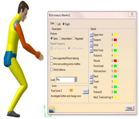
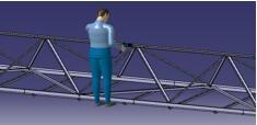
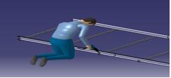
Criterion n°2: accessibility & posture. Accessibility & posture depends mainly on the fasteners positioning and the ease of access to a given part. A comfortable operator's posture reflects the facility of access to fixation point. In order to evaluate the degree of ease of access, we used CATIA CAD simulation software, where we introduce a human model in order to test the different possible postures impose for each positioning case, using the ergonomic tool “Rapid Upper Limb Assessment, RULA” an automated method allowing to have an ergonomic risk score by evaluating the solicitation degree of each body part in each stage of the disassembly operation [32]. Figure 2 shows an example of RULA analysis.
Table 2. Scores attributed to the types of tools
|
Tools |
description |
Corresponding connections |
score |
|
No tool |
Disassembly is effected by hand. |
- |
1 |
|
Simple tool |
Disassembly is effected using a simple tool such as a screwdriver, wrench, etc. |
Screwing, Bolting, etc |
0.7 |
|
Special tool |
The operation requires special tools such as the drill, pneumatic tools, etc. |
Riveting, etc |
0.51 |
|
Big tool |
Disassembly requires automatic, large and heavy tools such as saws, grinders, robot, etc. |
Welding, gluing, clinching, crimping, etc.. |
0.36 |
Figure 2. An example of RULA analysis
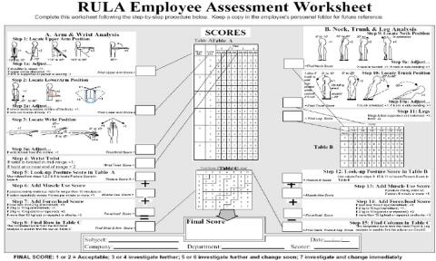
Figure 3. RULA sheet (Source: McAtamney and Corlett, 1993; with permission from Neese Consulting Inc., Leawood, KS, USA)
The final score ranges from 1 to 7:
-1 and 2: (Green) indicates that the posture is acceptable if it is not maintained or repeated for long periods of time.
-3 and 4: (Yellow) indicates that further investigation is needed and changes may be required.
-5 and 6: (Orange) indicates that investigation and changes are required soon.
-7: (Red) indicates that investigation and changes are required immediately.
RULA assesses the risk of upper limb disorders, which are divided into two main groups Figure 3: group A corresponds to upper arm, lower arm and wrist position, and group B for neck and trunk analysis. In fact, the final score of RULA depends on the following parameters:
-The type of posture, if it is static, intermittent or repetitive.
-The frequency of the repetition which determines the tasks frequency to be performed. Two choices are possible:
✓ Less than 4 times per minute.
✓ More than 4 times per minute.
-The weight of the object handled.
-The attitude of the shoulders and the arm.
A score scale from 0 to 1 is proposed for RULA risk scores to unify the scale of all criteria:
-1 and 2 correspond to 1.
-3 and 4 correspond to 0.6.
-5 and 6 correspond to 0.3.
-7 correspond to 0.
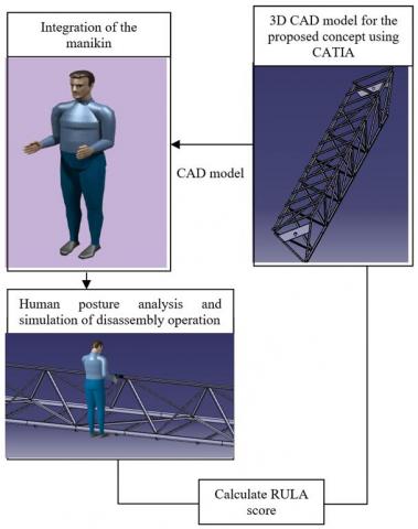
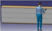
The Figure 4 shows the way in which we assess the accessibility criterion.
Criterion n°3: the end of life scenarios. The possible EoL scenarios of a product reflect the degree of disassembly efficiency. This means that the efficiency of this process is proportionally relative to the product recovery rate which determines the type of possible scenario. Generally, they exist different modes such as reuse, recycling, incineration and landfilling. While, the "reuse" scenario is the most favorable considering its ecological and economic advantages Figure 5.
Figure 4. Evaluation the ease of access through the operator’s posture
Table 3. Scores attributed to the different possible recovery rates
|
N° |
Levels |
The different possible cases |
score according to the case |
score according to the level |
Remarks |
|
Level 1 |
TR ≈ 100 % |
TL=TI =TRecy= 0 |
1 |
1 |
The 4 levels focus specifically on metallurgical products |
|
Level 2 |
TR>TRecy |
TL=TI =0 |
0.89 |
0.89 |
|
|
Level 3 |
TR<TRecy |
TL=TI =0 |
0.80 |
0.80 |
|
|
Level 4 |
TRecy ≈100% |
TL=TI =TR= 0 |
0,72 |
0,72 |
|
|
Level 5 |
TR+TRecy> TL+TI |
TR >TRecy |
0,65 |
0,56 |
- If the designer doesn’t have the precision of information as indicated in column 3, an average score corresponding to levels 3 and 4 has been fixed to facilitate the evaluation.
- Levels 5,6,7 concern all types of products, especially electrical products |
|
TR >TRecy TI <TL |
0,59 |
||||
|
TR <TRecy TI >TL |
0,53 |
||||
|
TR <TRecy TI <TL |
0,48 |
||||
|
Level 6 |
TR+TRecy< TL+TI |
TL <TI TRecy< TR |
0,43 |
0,37 |
|
|
TL< TI TRecy>TR |
0,39 |
||||
|
TL > TI TRecy< TR |
0,35 |
||||
|
TL > TI TRecy>TR |
0,31 |
||||
|
Level 7 |
TR = 0 TRecy = 0 |
|
0,28 |
0,28 |
Figure 5. Prioritization of different EoL scenarios [33]
According to its impact of the environment, we assign scores for each possible case using the semantic scale of 9 levels, then we use the AHP method to assess the weights (scores) and to classify these cases at different levels, as explained in the Table 3. The recovery rates for reuse and recycling are calculated as follow:
$T R=\frac{\text { number of reused components }}{\text { Total number of components }} * 100$ (1)
$T R e c y=\frac{\text { number of recycled components }}{\text { Total number of components }} * 100$ (2)
Criterion n°4: disassembly time. Time is a very important parameter to evaluate disassembly because it is a direct measurement of the labor cost, and thus the profitability of the operation.
To have an accurate estimate of the overall disassembly time, we have subdivided the disassembly operation into several sub-operations to facilitate time estimation. In addition, we have based on the operator's experience to estimate the time required to complete each sub-operation. The disassembly time includes:
Table 4 shows the time score scale we followed. The scores assigned for each time interval are estimated using the AHP method.
Table 4. Time scale-scores
|
Time |
Score |
|
0- 30min |
1 |
|
30min-1h30 |
0.70 |
|
1h30-2h30 |
0.51 |
|
2h30> |
0.36 |
2.2 Reference concepts (RC)
The notion of reference concepts aims to provide the designer with a reference helping them to evaluate the performance of newly proposed concepts. In our case, the reference concept represents the performance to the acceptable limit. To this end, we propose to create four reference concepts in order to delimit the field of admissible solutions during the conceptual design phase Figure 6, and this, through the elimination of the concepts which are below the thresholds of the four concepts. Our approach is based on the calculated distance between these reference concepts and the proposed concepts in order to decide to keep or to eliminate them. In other words, elimination of concepts that have a negative distance compared to the reference concepts created. These concepts depend initially to the project proposed by the company as well as its environmental policy followed, and which may adopt one or more reference concepts according to his environmental objectives.
The proposed reference concepts are based on the criteria explained in section 2.1.1: tool type, accessibility & posture, disassembly time and end-of-life scenarios. For each RC, we attribute the minimum acceptable scores for only three criteria, while the fourth criterion is estimated by an expert in the disassembly field and company officials, who make their choice taking into account the thresholds already fixed (the minimum scores necessary to accept the concept). The same exercise is repeated four times by alternating the choice of the criterion referenced by the expert and the other development officials. Figure 7 illustrates an example of creating a reference concept.
Figure 6. Delimitation of the solutions field proposed during the conceptual phase using the reference concepts
Figure 7. Example of creating a reference concept
The following Table 5 presents the four reference concepts created in our application case with the criteria thresholds fixed, and which are marked in red color:
Table 5. The four reference concepts created
|
Reference concepts Criteria |
Concept 1 |
Concept 2 |
Concept 3 |
Concept 4 |
|
Tool type |
0.51 |
0.7 |
0,51 |
0.51 |
|
End of life scenarios |
0.72 |
0,72 |
1 |
0.72 |
|
Accessibility & posture |
0 |
0 |
0 |
1 |
|
Time |
1 |
0.36 |
0.36 |
0.36 |
2.3 Evaluation and filtering of solutions
Once the RC are established, we proceed to evaluate the available concepts according to the criteria already mentioned, and to eliminate the inappropriate concepts using the formula (3), which represents the distance between the proposed concept and the four reference concepts.
$A=\frac{\Sigma w_{i}\left(C_{s i}-C_{r i}\right)}{\sum w_{i}}$ (3)
where, $C_{s i}$: The criterion corresponding to the proposed solution; $C_{r i}$: The criterion corresponding to the reference concept; $w_{i}$: Weight of criteria.
The main objective of this phase is to limit the number of design concept proposed during the conceptual phase. Through the elimination of concepts that have a negative distance compared to the reference concepts. A negative distance means that the concept is in unfeasible solutions scope. However, a positive distance allows to situate the proposed concept within the space of acceptable environmental performances.
2.4 Modification of disassembly / end of life strategies
This phase consists of improving the disassembly performance of a concept which is considered inappropriate after having a negative distance from the reference concepts. Sometimes, a concept can be eliminated just because it had low scores for certain criteria. So, instead of proceeding directly to elimination, we propose through this phase to propose end-of-life and disassembly strategies in order to further improve the criteria that had poor scores in the beginning. These modifications allow to make the concept above the thresholds of the reference concepts, which always represent the minimum scores to accept a concept.
The following diagram (Figure 8) summarizes all different steps of disassembly evaluation:
Figure 8. The steps of the proposed approach
The chosen application case is the support of a solar collector. Its main function is to concentrate and redirect sunlight on to absorber tubes to heat up the working fluid. The recovered heat is then used to generate high pressure steam which drives a turbine in order to produce electricity. The solar collector is composed of a reflecting surface and a metal structure, whose function is to give and maintain reflecting glass shape. In our study, only the design of supporting structure is treated. In fact, we consider three different concepts of the supporting structure (sandwich, tube, truss). Figure 9. We will adopt one type of fixation for the three proposed concepts which is “riveting”.
As previously explained, the type and location of fastener imposes the type of tool to be used as well as the ease of access to the fasteners and the operator’s posture.
Therefore, we will try to study our application case based on the evaluation criteria previously explained in section 2.1.1: tools type, disassembly time, accessibility & posture and end-of-life scenarios.
Criterion n°1: tool type
Table 6 presents the scores assigned to the types of tools chosen to evaluate the disassembly of every proposed concept. Indeed, the three concepts obtain an identical score because the tool used is the same.
Criterion n°2: accessibility & posture
The evaluation of this criterion is based on CAD models of the three concepts studied, in order to virtually visualize and analyze the accessibility at the fixation point. The evaluation method of this criterion is well detailed in (2). The ergonomic risk score provided by RULA reflects the degree of accessibly to the fixation point. The risk score assigned to the sandwich and tube concepts presented in Table 7 is due to the visibility of the attachment points and also to the ease with which the operator can access to the attachment points, which explains an acceptable ergonomic score. However, the risk score attribute to the truss concept reflects that this posture is not appropriate and requires further study and needs to be changed quickly. Obtaining this score reflects the complexity of the structure of this concept which causes a difficulty of access to the fixing points which obviously has a negative influence on the operator's posture.
Table 6. Scores attributed to the tools type used in the three cases
|
Concepts |
Tool type |
Score |
Observations |
|
Sandwich |
Special |
0.51 |
The corresponding type of fastening is riveting. The disassembly tool used is "the drill". |
|
Truss |
Special |
0.51 |
The corresponding type of fastening is reveting. The disassembly tool used is "the drill". |
|
Tube |
Special |
0.51 |
The corresponding type of fastening is riveting. The disassembly tool used is "the drill". |
Table 7 shows the different operator’s postures corresponding to the three selected concepts.
Criterion n°3: disassembly time
The time parameter includes the tool preparation time, the access time to fastener position, the disassembly time and the fastener removal time.
Among the three concepts mentioned above, the sandwich concept is the only one that took a lot of time during disassembly, explained by the large number of fasteners to be disassembled .While, the tube concept is considered the most advantageous, despite the high quantity of fixings, but they are easier and quicker to remove.
Table 8 shows the time required for every task performed in the three concepts in order to conclude the overall disassembly’s time.
Criterion n°4: end-of-life scenarios
Table 9 shows the scores assigned to each possible end-of-life scenario in the three selected concepts, which are based on the product's recovery rate.
Figure 9. The three studied concepts of solar collector support
Table 7. The different possible operator’s postures for the three concept’s disassembly
|
Sandwich concept |
RULA score |
Average RULA score |
Truss concept |
RULA Score |
Average RULA score |
||
|
Rank 1 |
0.6 |
0.6 |
Upper chord |
0.6 |
0.3 |
||
|
Rank 2 |
0.6 |
Diagonal bare |
0.3 |
||||
|
Rank 3 |
1 |
Lower chord (1) |
0.3 |
||||
|
Rank 4 |
0.6 |
Lower chord (2) |
0.3 |
||||
|
Tube concept |
RULA Score |
||||||
|
0.6 |
|||||||
|
Time (s)
concepts |
Tool preparation |
Access to fastener |
Disassembly |
Removal of fixation |
Time between two fasteners |
Number of fixations |
The overall time of concept disassembly |
Score |
||
|
Truss |
Upper chord |
10 |
2 |
40 |
2 |
2 |
50 |
160 |
2h |
0.51 |
|
Diagonal bar |
3 |
2 |
70 |
|||||||
|
Lower chord 1 |
4 |
2 |
30 |
|||||||
|
Lower chord 2 |
3 |
2 |
10 |
|||||||
|
Tube |
10 |
1 |
40 |
2 |
1 |
110 |
1h30min |
0.70 |
||
|
Sandwich |
Alternative 0 |
15 |
1 |
40 |
2 |
1 |
1100 |
13h44min |
0.36 |
|
Table 9. The scores attributed to the three cases studied according to the rate and level of recovery
|
Concepts |
Level |
Score |
|
Truss concept |
2: TR> TRecy |
0.89 |
|
Tube concept |
3: TR< TRecy |
0.80 |
|
Sandwich concept |
3: TR< TRecy |
0.80 |
The truss concept is the highest ranked, for the reason that the disassemble components can be reused later because they are intact. In contrast, the tube and sandwich concepts are two concepts qualified as Level 3, characterized by a higher recyclable recovery rate than the reusable recovery rate.This is a critical level and the lowest for metallurgical products. This result is mainly due to components with holes and which have lengths that cannot be reused.
The following Table 10 summarizes the disassembly evaluation results of the three concepts based on the four criteria chosen and in comparison with the scores of reference concepts.
Table 10. The disassembly the evaluation results of the three concepts
|
Reference concepts |
Study cases |
$A=\frac{\sum w_{i}\left(C_{s i}-C_{r i}\right)}{\Sigma w_{i}}$ |
|||||||||
|
Evaluation criteria |
Criteria weight (wi) |
R. C n°1 |
R. C n°2 |
R. C n°3 |
R. C n°4 |
Truss |
Tube |
Sandwiche |
Truss |
Tube |
Sandwiche (alternative 0) |
|
Tools type |
1.95 |
0,51 |
0,7 |
0,51 |
0,51 |
0,51 |
0,51 |
0,51 |
0,27 |
0,71 |
-0,07 |
|
End of life scenarios |
1.32 |
0,72 |
0,72 |
1 |
0,72 |
0,89 |
0,72 |
0,8 |
|||
|
Accessibility& posture |
0.37 |
0 |
0 |
0 |
1 |
0,3 |
0,6 |
0,6 |
|||
|
Time |
5.05 |
1 |
0,36 |
0,36 |
0,36 |
0,51 |
0,70 |
0.36 |
|||
|
|
Results |
Keep the solution |
Keep the solution |
Eliminate the solution |
|||||||
After comparing the evaluation criteria of the three concepts with the reference thresholds according to the distance expressed in formula (3), we noticed that the concept "sandwich" obtains a negative score which means it is inferior to the reference concepts and thus to acceptance threshold, which requires its elimination. Based on Table 10, this result can be explained by:
The long time that it requires during the disassembly phase, unlike the other concepts, because of the large number of fasteners used (1100 rivets), as well as the type of tool chosen (drill), which remains ineffective for removing such a large number of fasteners in acceptable time.
Recyclable recovery rate higher than the reusable recovery rate. This is mainly due to the large number of fasteners used, that caused holes in the upper and lower plate which influences negatively its product's recovery rate.
Based on the results concluded regarding the sandwich concept, the concept has been eliminated, even if it represents other advantages concerning other criteria. To remedy this, instead of eliminating it directly, we will make modifications in the disassembly / end of life strategies and re-evaluate the concept to see how the performance of the concepts evolves.
6.1 Strategy 1
We suggest using an automated and autonomous tool (robot) to remove the fasteners to reduce disassembly time, avoid the risk of having uncomfortable positions for the operator and to reduce physical effort. This alternative permit to improve the scores of this concept to 0.51 for the disassembly time criterion and to 1 for the accessibility & posture criterion. However, the score assigned to the tool type is 0.36, because this type of equipment is expensive and difficult to obtain, available only on order. Hence, these modifications raise the final distance to a positive distance of 0.2 compared to the reference concepts.
6.2 Strategy 2
Since the recovery rate of the end-of-life product is mostly recyclable, therefore, we propose to proceed directly to the recycling of the concept, without going through the disassembly operation. This strategy allowed us to have a better score of 1, for the following two criteria: disassembly time, accessibility & posture. However, the scores assigned to the EoL scenarios criterion is 0.72 and 0.36 for tool because the product must be cut with shears before it can be loaded into an oven, the type of tool considered is "big tool". These obtained scores give a distance of 1.2 compared to the reference concepts. In fact, the results obtained for the both strategies Table 11, indicate that strategy 2 is the most suitable, since it is the alternative that represents the greatest positive distance from the reference concepts.
We indicate that the green color in the following table indicates the best results of the two strategies, while the red color indicates the results of the strategy initially followed.
Table 11. The results obtained after the implementation of the two proposed strategies
|
Sandwich concept |
The initial alternative |
Strategy 1 |
Strategy2 |
|
Alternative 0 |
Alternative1 |
Alternative2 |
|
|
Tool type |
0.51 |
0.36 |
0.36 |
|
End of life scenarios |
0.80 |
0.80 |
0.72 |
|
Accessibility & posture |
0.6 |
1 |
1 |
|
Time |
0.36 |
0.51 |
1 |
|
Distance A |
-0.07 |
0.2 |
1.2 |
The main objective of the proposed approach is to help evaluating disassembly of product from the conceptual phase, thus delimiting the field of proposed concepts. And this, through the evaluation and comparison of these concepts using the technique of reference concepts introduced in our approach to define the scope of feasible solution based on the following evaluation criteria: type of disassembly tools, accessibility and operator’s posture during disassembly, disassembly time and the chosen end-of-life scenarios. Any solution above the thresholds of the four concepts, reflected by a negative distance, is a rejected solution.
The application of this approach to our industrial case allows the decision-maker to have a reduced number of the proposed concepts through the elimination of the concept that is not in conformity with the reference concepts suggested. The experiment on an industrial case also reveals the possibility to improve the disassembly performance of the rejected concept, through the proposed end-of-life strategy, in order to avoid the risk of eliminating an interesting concept just because certain disassembly criteria have low scores.
Overall, it is possible to conclude that the proposed approach is appropriate to use at the beginning of the design, especially during the conceptual phase given the considerable impact of the decisions taken during this stage for having an ecological product.
The integration of virtual reality for an exact estimation of the disassembly time, as well as the consideration of uncertainty during the environmental decision making in the first phases, are among the interesting points that will be considered in the future works.
[1] Harivardhini, S., Krishna, K.M., Chakrabarti, A. (2017). An integrated framework for supporting decision making during early design stages on end-of-life disassembly. Journal of Cleaner Production, 168: 558-574. https://doi.org/10.1016/j.jclepro.2017.08.102
[2] Gungor, A., Gupta, S.M. (1997). An evaluation methodology for disassembly processes. Computers & Industrial Engineering, 33(1-2): 329-332. https://doi.org/10.1016/S0360-8352(97)00104-6
[3] Lambert, A.J.D. (1999). Linear programming in disassembly/clustering sequence generation. Computers & Industrial Engineering, 36(4): 723-738. https://doi.org/10.1016/S0360-8352(99)00162-X
[4] Kuo, T.C. (2006). Enhancing disassembly and recycling planning using life-cycle analysis. Robotics and Computer-Integrated Manufacturing, 22(5-6): 420-428. https://doi.org/10.1016/j.rcim.2005.11.014
[5] Moore, K.E., Güngör, A., Gupta, S.M. (2001). Petri net approach to disassembly process planning for products with complex AND/OR precedence relationships. European Journal of Operational Research, 135(2): 428-449. https://doi.org/10.1016/S0377-2217(00)00321-0
[6] Bentaha, M.L., Voisin, A., Marangé, P. (2020). A decision tool for disassembly process planning under end-of-life product quality. International Journal of Production Economics, 219: 386-401. https://doi.org/10.1016/j.ijpe.2019.07.015
[7] Mandolini, M., Favi, C., Germani, M., Marconi, M. (2018). Time-based disassembly method: How to assess the best disassembly sequence and time of target components in complex products. The International Journal of Advanced Manufacturing Technology, 95(1-4): 409-430. https://doi.org/10.1007/s00170-017-1201-5
[8] Smith, S., Hsu, L.Y., Smith, G.C. (2016). Partial disassembly sequence planning based on cost-benefit analysis. Journal of Cleaner Production, 139: 729-739. https://doi.org/10.1016/j.jclepro.2016.08.095
[9] Kheder, M., Trigui, M., Aifaoui, N. (2017). Optimization of disassembly sequence planning for preventive maintenance. The International Journal of Advanced Manufacturing Technology, 90(5-8): 1337-1349. https://doi.org/10.1007/s00170-016-9434-2
[10] Favi, C., Germani, M., Mandolini, M., Marconi, M. (2012). LeanDfd: A design for disassembly approach to evaluate the feasibility of different end-of-life scenarios for industrial products. In Leveraging Technology for a Sustainable World, Berlin, Heidelberg, pp. 215-220. https://doi.org/10.1007/978-3-642-29069-5_37
[11] Lee, H.M., Lu, W.F., Song, B. (2014). A framework for assessing product End-of-Life performance: Reviewing the state of the art and proposing an innovative approach using an End-of-Life Index. Journal of Cleaner Production, 66: 355-371. https://doi.org/10.1016/j.jclepro.2013.11.001
[12] Favi, C., Germani, M., Luzi, A., Mandolini, M., Marconi, M. (2017). A design for EoL approach and metrics to favour closed-loop scenarios for products. International Journal of Sustainable Engineering, 10(3): 136-146. https://doi.org/10.1080/19397038.2016.1270369
[13] Favi, C., Marconi, M., Germani, M., Mandolini, M. (2019). A design for disassembly tool oriented to mechatronic product de-manufacturing and recycling. Advanced Engineering Informatics, 39: 62-79. https://doi.org/10.1016/j.aei.2018.11.008
[14] Li, J., Barwood, M., Rahimifard, S. (2019). A multi-criteria assessment of robotic disassembly to support recycling and recovery. Resources, Conservation and Recycling, 140: 158-165. https://doi.org/10.1016/j.resconrec.2018.09.019
[15] Mok, H.S., Kim, H.J., Moon, K.S. (1997). Disassemblability of mechanical parts in automobile for recycling. Computers & Industrial Engineering, 33(3-4): 621-624. https://doi.org/10.1016/S0360-8352(97)00207-6
[16] Kroll, E., Hanft, T.A. (1998). Quantitative evaluation of product disassembly for recycling. Research in Engineering Design, 10(1): 1-14. https://doi.org/10.1007/BF01580266
[17] Desai, A., Mital, A. (2003). Evaluation of disassemblability to enable design for disassembly in mass production. International Journal of Industrial Ergonomics, 32(4): 265-281. https://doi.org/10.1016/S0169-8141(03)00067-2
[18] Haoues, N., Cornier, A., Zwolinski, P. (2003). Influence des choix de conception sur le désassemblage pour l’environnement. In Conférence PRIMECA.
[19] Sabaghi, M., Mascle, C., Baptiste, P. (2016). Evaluation of products at design phase for an efficient disassembly at end-of-life. Journal of Cleaner Production, 116: 177-186. https://doi.org/10.1016/j.jclepro.2016.01.007
[20] Zimmer, L., Zablit, P. (2001). "Global Aircraft" pre-design based on constraint propagation and interval analysis. DGLR BERICHT, (5): 77-86.
[21] Giapoulis, A. (2000). Einsatz von Methoden zur Produktentwicklung in der industriellen Praxis. VDI-Berichte, 1-9.
[22] Beitz, W., Pahl, G., Grote, K. (1996). Engineering design: A systematic approach. MRS Bulletin, 71. https://doi.org/10.1557/S0883769400035776
[23] Keoleian, G.A., Menerey, D. (1993). Life cycle design guidance manual. Environmental requirements and the product system. Final report (No. PB-93-164507/XAB). National Pollution Prevention Center, Ann Arbor, MI (United States).
[24] Kroll, E., Carver, B.S. (1999). Disassembly analysis through time estimation and other metrics. Robotics and Computer-Integrated Manufacturing, 15(3): 191-200. https://doi.org/10.1016/S0736-5845(99)00026-5
[25] Dowie, T., Simon, M. (1994). Guidelines for designing for disassembly and recycling. Manchester Metropolitan University. Manchester.
[26] de Aguiar, J., de Oliveira, L., da Silva, J.O., Bond, D., Scalice, R.K., Becker, D. (2017). A design tool to diagnose product recyclability during product design phase. Journal of Cleaner Production, 141: 219-229. https://doi.org/10.1016/j.jclepro.2016.09.074
[27] LeBel, L. (2009). Prise de décision multi critères. Prise de décision Multi critères. Université Laval.
[28] Saaty, T.L. (1977). A scaling method for priorities in hierarchical structures. Journal of Mathematical Psychology, 15(3): 234-281. https://doi.org/10.1016/0022-2496(77)90033-5
[29] Saaty, T.L. (1990). How to make a decision: The analytic hierarchy process. European Journal of Operational Research, 48(1): 9-26.
[30] Mankins, J.C. (1995). Technology readiness levels. White Paper.
[31] Conrow, E.H. (2011). Estimating technology readiness level coefficients. Journal of Spacecraft and Rockets, 48(1): 146-152. https://doi.org/10.2514/1.46753
[32] McAtamney, L., Corlett, E.N. (1993). RULA: A survey method for the investigation of work-related upper limb disorders. Applied Ergonomics, 24(2): 91-99. https://doi.org/10.1016/0003-6870(93)90080-S
[33] Johansson, G. (1997). Design for disassembly-A framework, licentiate thesis at the division of production system, department of mechanical engineering at Linköping Universitet. AFR-report, 174: 1997.