Haowei Yao*![]() | Kefeng Lv
| Kefeng Lv![]() | Shengkai Yan
| Shengkai Yan![]() | Mengyang Xing
| Mengyang Xing![]() | Zhen Lou
| Zhen Lou![]() | Wei Ren
| Wei Ren![]()
© 2023 IIETA. This article is published by IIETA and is licensed under the CC BY 4.0 license (http://creativecommons.org/licenses/by/4.0/).
OPEN ACCESS
As an important part of the power system, oil-immersed transformers have a complex structure with a large oil storage capacity and a high-risk factor. The fire simulation software PyroSim was used to simulate the burning process of oil-immersed transformers under different fire scenarios, in order to investigate the vulnerability of oil-immersed transformer oil to fire. Surface according to simulation results: burning oil from oil-immersed transformers tends to form a fire plume and ignite other components such as transformer bushings. The ambient wind speed where the fire is located has a large effect on the spread of the fire's flames; the different rates of heat release from the fire source have little effect on the flames, but have a large effect on the overall process of fire development. The corresponding components therefore need to be protected against fire and the transformer insulating oil needs to be tested regularly.
oil-immersed transformers, PyroSim, simulation studies, fire plume flow
In recent years, the development of long-distance high-voltage DC transmission projects has resulted in occasional fire accidents in extra-high voltage converter substations, causing huge economic losses and posing a serious threat to the production of staff stationed at the stations and the work of rescue personnel [1, 2]. As the key equipment for transforming and transmitting electrical energy in power systems, power converter transformers are widely used in power plants and substations [3, 4]. An example is the oil-immersed converter transformer that connects the converter bridge to the AC system in extra-high voltage DC transmission projects. Oil-immersed transformers are the most common type of power transformer with high voltage levels, complex working conditions, high operating temperatures and enormous dimensions [5]. It contains a large amount of flammable liquid insulating oil inside, which, in the event of a fire, often spreads easily and is difficult to extinguish, posing a safety risk to operators and a risk of soil surface water contamination [6]. At the same time, the unstable operation of the grid can also have a negative impact on social and economic development [7], so it is vital to ensure the safe operation of transformers.
In practical application scenarios, oil-immersed transformers are often surrounded by cables of various types. In the event of a fire, the large amount of burning insulating oil can melt the cables and steel around the transformer at high temperatures. It could cause a collapse and pose a greater safety risk for rescuers. Cai et al. [8] studied the cores of oil-immersed transformers and learned that core fires can lead to transformer fires. Due to damage to the insulation between the silicon steel sheets or between the core and the clamping bolts, eddy currents are caused to heat up the core, causing the insulation oil to decompose and burn. Chen et al. [9] found through the analysis of the causes and high incidence areas of large converter transformer fires, the influencing factors and development process of transformer explosion fires, and the characteristics of casing explosion fire accidents. High-voltage casing is a high incidence of fire in large oil-immersed transformers; transformer internal fault arc energy up to a certain value, can lead to an explosion in the tank, an explosion can start a fire, and leakage to the air of the gas mixture to reach the explosive limit and whether there is enough ignition energy is closely related. Li et al. [10] found that oil-filled equipment such as transformers in long-term overload operation and degraded transformer oil can present a higher risk of fire ignition by electric arcs. Dai et al. [11] conducted a full-scale experimental fire study on a 35kV outdoor transformer to explore the combustion characteristics of a substation under fire conditions. The results show that transformer fires are insidious, three-dimensional and multi-scale combustion characteristics. Zhang et al. [12] used CFD numerical simulation technology to study the occurrence and development process of transformer fire in a typical UHV converter station, and came up with some measures for transformer fire extinguishing. Wang et al. [13] found that an increase in ambient wind speed contributed to the burning rate of smaller hollow pallet oil pool fires, but had no effect on larger hollow pallet oil pool fires. Two empirical correlations are presented to predict the critical burning rate for consolidation on a hollow tray. The predictions were found to be in fairly good agreement with the measurements. Vali et al. [14] investigating the combustion characteristics of oil pool fires found that at a specified pool bottom temperature, the combustion rate and flame height increased with pool depth, with shallow pools being more sensitive to the pool bottom boundary temperature and the combustion rate and dimensionless temperature structure being independent of the bottom temperature.
The drawbacks of using experiments for oil-immersed transformer fires are considered, such as the high cost and the high danger. In this paper, PyroSim, a fire dynamics simulation software, is used to numerically model and design a fire scenario for a ±220 kV oil-immersed transformer. The flame spread at different locations of the ignition point during the fire, the temperature above the ignition point, and the heat release rate profile under different wind speed ambient conditions are investigated for analysis.
2.1 Theoretical foundations of simulation technology
PyroSim uses the equations of conservation of energy, conservation of mass and conservation of momentum for the simulation of the model in order to make the results more accurate. The software divides the set space into a number of small 3D rectangular control bodies or computational cells. Using the equations of conservation of mass, momentum and energy, the division is carried out to calculate the thermal radiation, turbulence in fluid flow in each grid by the finite volume method, and to track and predict the generation and movement of flames and smoke and combine this with the properties of the flaming material to calculate the propagation and spread of the fire.
The conservation equations for the mass, momentum and energy of the fluid used in the calculations are as follows [15]:
Conservation of mass equation:
$\frac{\partial p}{\partial t}+\nabla \cdot \rho \mu=0$ (1)
Conservation of momentum equation:
$\frac{\partial}{\partial t}(\rho \mu)+\nabla \cdot \rho \mu+\nabla \rho-\rho g=f+\nabla \cdot \tau_{i j}$ (2)
Conservation of energy equation:
$\frac{\partial}{\partial t}(\rho h)+\nabla \cdot \rho h \mu=\frac{D p}{D t}+\dot{q}^{\prime \prime \prime}-\nabla \cdot \dot{q}^{\prime \prime}+\emptyset$ (3)
Ideal state gas equation:
$p=\frac{\rho R T}{\bar{w}}$ (4)
2.2 Oil-immersed transformer models
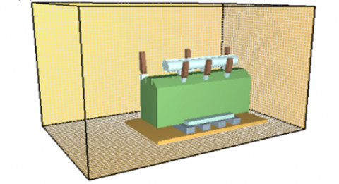
The numerical model in this paper mainly refers to a ±220kV oil-immersed transformer. The actual project ±220kV oil-immersed transformer is shown in Figure 1(a). A three-dimensional model of the oil-immersed transformer was created using PyroSim software, which simplified the modelling in accordance with the structure and actual dimensions of the building. The tank length, width and height are: 12m × 4m × 5m, respectively, and the oil pillow is 8 m long and 1.5 m in diameter in a column. The thickness of the entire transformer housing is set to 0.1 m and coloured green; the thickness of the oil conservator is set to 0.1 m and coloured white. The oil-immersed transformer as a whole is in an oil discharge tank, supported by four concrete blocks. In addition, a reasonable simplification of the transformer has been made taking into account the factors affecting the fire and the effect of the model is shown in Figure 1(b).
(a) ±220kV oil-immersed transformers
(b) ±220kV oil-immersed transformer 3D model drawing
Figure 1. Diagram of ±220kV oil-immersed transformer
2.3 Division of the grid
When using PyroSim software for simulation calculation, it is necessary to divide the grid. The finer the grid is divided, the smaller the calculation error will be, but more calculation time will be consumed [16]. In this paper, the model is reasonably meshed, taking into account the simulation accuracy and computer processing power. The grid size is: 24m × 16m × 16m. The model's simulation calculation space is divided into: 0.4m × 0.4m × 0.4m size grids, and the total number of grids after division is 96,000, which is within the capacity of the computer to handle.
2.4 Fire simulation scenario setting
The identification of fire hazards is a fundamental part of the design of a fire scenario, which focuses on the analysis of possible fire risks, the types of combustible materials, combustible burning characteristics, etc. The fire hazard of oil-immersed power transformers stems from the transformer oil, which in this simulation is a hydrocarbon with a flash point of approximately 140℃ and an ignition point of 165 to 190℃ [17]. The selected fire source type is a "T" square fire. The maximum heat release rate for transformer oil No. 25 is 3000 kW/m2 and the minimum heat release rate is approximately 1400 kW/m2 at different initial temperatures. In the actual course of a fire, natural factors such as temperature in the environment and surrounding wind speed, all have a significant impact on the process of fire combustion [18].
In this paper, two different maximum and minimum heat release rate cases are set up in the simulation of the spread of oil-immersed transformer fires, the ambient temperature is a high summer temperature of 40 °C and different ambient wind speeds (no wind, light wind and strong wind) are simulated and the results are compared and analysed. According to the literatures [19-21], it is known where fires often occur in oil-immersed transformers, and in this paper three fire source locations are set up in the model, as shown in Figure 2.
Figure 2. Simulated fault location diagram for ±220kV oil-immersed transformers
Fire source location 1 in Figure 2(a), may occur winding fire, poor contact, transformer oil leakage, etc. will lead to fire inside the tank, often causing a large number of oil vapour gathering, triggering the box bursting and burning. Fire source location 1 in Figure 2(b), insulation of the porcelain casing surface may occur flash arc, due to the oil in the wire spacing is too small, or insulating oil moisture, dirt, aging, easy to arc, causing the burning of oil, the formation of spreading fire. Fire source position 3 in Figure 2(c), on the side of the transformer, near the side of the high voltage winding, consider the spread of flame and smoke after a winding fire under natural conditions.
The relevant parameters in the PyroSim software have been set and, based on the oil-immersed transformers considered in this study, the following relevant parameters were set for the simulation.
In this paper, three different wind speeds are set for no wind (0 m/s), light wind (5 m/s) and strong wind (10 m/s). Simulation of different fire scenarios, the simulation time is 240s, and the arrangement of several temperature observation points, focusing on the study in different heat release rate, different heat release rate, oil-immersed transformer combustion process, and its temperature change.
3.1 Analysis of flame combustion simulation results
3.1.1 Analysis of flame simulation results in windless scenarios
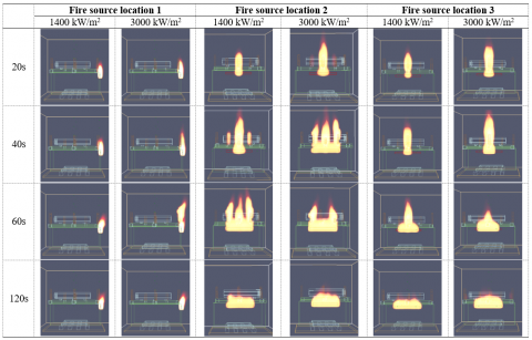
A comparative analysis of the development of flames during an oil-immersed transformer fire in a windless scenario was carried out to analyse the flame changes at 20 s, 40 s, 60 s and 120 s after fire initiation for fire location 1, fire location 2 and fire location 3 respectively at two different heat release rates, the flame changes are shown in Table 1.
Table 1. Flame variation at different fire locations with different heat release rates without wind
As shown in Table 1, in a windless scenario, the flame pattern at fire location 1 remains more or less constant towards a steady state. Significant difference in flame height at different rates of heat release. Significant increase in flame height at higher 60s heat release rates (3000 kW/m2). This is due to the overflow of transformer oil vapour inside the high voltage casing on the left side of the flame, which starts to burn violently under the effect of the thermal radiation of the flame. At the low heat release rate (1400 kW/m2), the internal temperature of the high pressure casing to the left of the flame was low and failed to induce fuel vapour, so there was no fire spread. Due to the simulated wind-free environment, the shape of the flame did not appear skewed and eventually returned to its initial shape.
The contrasting changes in flame development at different heat release rates are more evident for fire location 2. At 20 s, the height and brightness of the flame differed significantly at different rates of heat release. A low heat release rate (1400 kW/m2), with the flame just starting to spread at 40 s, with the surface of the casing above the source starting to burn and smaller flames appearing on the surface of the casing on either side of the source. Violent burning of the surface of the insulating sleeve at 60 s. The flame becomes smaller at 120 s when the oil and gas on the surface of the casing is largely burnt out, but the flame height is still lower than the flame height at the heat release rate (3000 kW/m2). In the case of heat release rate (3000 kW/m2), the combustion developed to 40 s when the flame had finished spreading to both sides and the oil and gas inside the low-pressure casing overflowed to the surface of the casing, all of which were ignited by the flame. At 60 s, the flame has started to diminish. At 120s, the transformer oil overflowing from the surface of the three low voltage bushings burns out and the flame becomes smaller.
The flame development at fire location 3 varies approximately the same for different heat release rates. However, the flame heights differed, with the flame height for the heat release rate (3000 kW/m2) being higher at 40 s than for the heat release rate (1400 kW/m2). This is because at the higher heat release rate, the transformer oil gas overflowing from the high voltage bushing surface burns faster and burns through the transformer oil earlier than the lower heat release rate, so forming a difference in flame height.
3.1.2 Analysis of flame simulation results in light wind scenarios
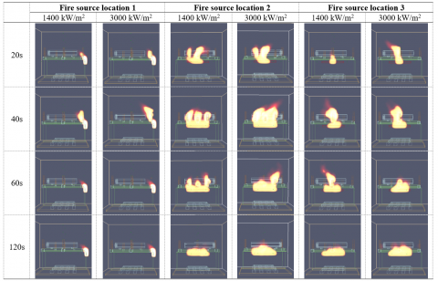
Comparative analysis of flame development during an oil-immersed transformer fire in light wind (5 m/s) scenario. The flame changes at 20 s, 40 s, 60 s and 120 s after fire initiation for fire location 1, fire location 2 and fire location 3 are analysed separately for two different heat release rate scenarios and are shown in Table 2.
Table 2. Flame variation at different fire locations with different heat release rates in light wind (5m/s)
As shown in Table 2, the development of the flame at different heat release rates varied approximately equally for fire location 1 in light wind (5m/s) scenario. The low rate of heat release from the fire source (1400 kW/m2), as the flame spread faster due to the influence of the side wind and the flame skewed to the left, quickly igniting the transformer oil spilled on the surface of the high voltage bushing to the left of the fire source. At 60 s, the transformer oil on the surface of the high voltage bushing starts to burn violently until it burns out. Rate of heat release (3000 kW/m2), blowing up of the high-voltage insulating bushing at 40 s and blast ignition of the overflowing transformer oil. At 60s the transformer oil on the high voltage bushing is largely burnt out. Eventually the flame of the fire source stabilises in both cases.
Fire location 2 has a large initial variation in flame development at different heat release rates, with roughly the same contrast in later changes. Under the heat release rate (3000 kW/m2), the height of the flame at 20 s is higher and the burning area is larger because the flame burns more vigorously at the beginning of the higher heat release rate, and the flame spreads faster due to the influence of the wind. At 40 s, the flame burning pattern is the same for the different heat release rates. This is because under the heat release rate (3000 kW/m2) conditions, the fault point has been burning long enough for the spilled transformer oil to become less and the height of the flame to become lower, while the spilled transformer oil on the surface of the low voltage bushing within the 1400 kW/m2 scenario has just started to burn and there is sufficient combustible material, so the height of the flame is higher. In the 60 s of the fire, the transformer oil overflowing from the middle low-voltage bushing has been completely burned, and the oil and gas overflowing from the surface of the other two low-voltage bushings are also burning in varying degrees. As the fire continued to develop all of the transformer oil that had overflowed from the surface of the three low-voltage insulating bushings burned away and the flames eventually remained stable.
The development of the flame at fire location 3 is essentially the same. Apart from the difference in flame height, there are no other significant differences. When the fire developed to 40 s, the transformer oil spilled in the middle of the high voltage casing in both cases had started to burn vigorously and the flames spread rapidly to both sides, as the fire continued to develop the spilled transformer oil burned out and the flames eventually remained stable.
3.1.3 Analysis of flame simulation results in strong wind scenarios
A comparative analysis of the flame development during an oil-immersed transformer fire in a strong wind (10 m/s) scenario is presented below. The flame changes at 20 s, 40 s, 60 s and 120 s after fire initiation for fire location 1, fire location 2 and fire location 3 respectively under two different heat release rate scenarios are shown in Table 3.
Table 3. Flame variation at different fire locations for different heat release rates in strong winds (10 m/s)
As can be seen in Table 3, the trends in flame development for different heat release rates are approximately the same for fire source location 1 in a strong wind scenario. Both were affected by strong winds at 40 s and the flame skewed to the left, igniting the transformer oil spilled on the surface of the high voltage bushing and burning most intensely. Depending on the heat release rate of the fire source, the flame height is higher for higher heat release rates (3000 kW/m2). At 60 s the transformer oil spilled on the surface of the high voltage casing to the left of the fire has burned out and the flame of both tends to burn steadily.
The variation of the flame for different heat release rates at fire location 2 is essentially the same initially and varies later. At the beginning of the 20 s burn, both ignited the low pressure casing above and to the upper left of the fire, due to the flame skewing to the left in response to the strong wind on the right. At 40 s both ignited the three low pressure bushings, the low pressure bushing surface transformer oil vapour at a higher heat release rate (3000 kW/m2) and the flame occurred as a boom, giving the fire a flaming shape. After 60 s the flame on the two low pressure bushings was the first to go out due to the high heat release rate (3000 kW/m2) of the bombardment which accelerated the consumption of transformer oil on the surface of the low pressure bushings above and to the left of the fire source location. At 120 s both flames are essentially in a steady state of combustion.
The development of the flame at fire location 3 varied in approximately the same way for different heat release rates, both igniting only one high pressure casing. This is due to the large gap between the transformer's high voltage bushings, which makes flame spread more difficult. The high heat release rate (3000 kW/m2) is the first to ignite the high pressure casing at the beginning of the combustion and the flame is higher than the low heat release rate (1400 kW/m2) during the combustion. But at 60 s the high heat release rate (3000 kW/m2) transformer oil is consumed, so the flame height is low. 120s later all enter the stable combustion phase.
In the oil-immersed transformer fire, in different locations of the fire point, wind speed on the spread of fire flames are great, while the rate of heat release from the fire source on the flame is not significant, but the overall process of fire development has a great impact, combined with the above unified analysis as follows.
(1) In no wind, flames can be seen in three locations starting to spread from the sides of the transformer case, and as the fire continues to grow, the flames become larger forming a plume of fire that is narrow at the top and wide at the bottom.
(2) In light wind (5 m/s) the flames develop completely differently from those in no wind, the flames are not vertical but inclined in the direction of the wind, and the fire will be larger at the same moment with high wind speed compared to a windless scenario.
(3) In strong winds (10 m/s) the fire develops rapidly and the flames spread even more rapidly, with the spilled combustible material largely burnt out by the time the fire has developed to 60 s. There is no obvious rule for the spread of the fire.
3.2 Analysis of heat release rate simulation results
It is clear from the above section that different fire-starting points and ambient wind speeds have different effects on the development of a fire. In this paper, the effect of wind speed on fires at different locations is selected for overall heat release rate analysis in scenarios with more significant changes in high heat release rates (3000 kW/m2).
(a) Location of fire source 1
(b) Location of fire source 2
(c) Location of fire source 3
Figure 3. Overall heat release rate curve during fire
As can be seen from Figure 3. In no wind, the maximum heat release rate reached 25000 kW for the three different fire locations, while the maximum heat release rates reached 28000 kW and 33000 kW in light wind (5 m/s) and wind strong (10 m/s), respectively, with significant differences in the trends of the three curves. Relatively stable fire curves for oil-immersed transformers in no wind. At 20 s, the heat release rate curve tends to rise sharply at all three different positions, due to the spread of the flame igniting the transformer oil spilled on the surface of the high voltage bushing or low voltage bushing of the oil-immersed transformer. In particular, the fire scenes in fire location 2. A threefold increase in the heat release rate in the three wind speed scenarios, due to the small spacing of the low voltage bushings at fire location 2 and the ease with which the flames ignite the three bushings, causing the burning of the transformer oil spilling over the surfaces of the three low voltage bushings, resulting in a dramatic increase in the overall heat release rate. In the case of strong winds (10 m/s), the rate of heat release does not vary much between scenarios. The fires in all three scenarios have essentially stabilised and progressed to the decline stage after 80 s, with the heat release rate per unit area essentially remaining at 3000 kW/m2.
Numerical simulations of fires in oil-immersed transformers have been carried out, and the flame development process and heat release rate curves at different ignition point locations and different wind speeds have been analysed. The following conclusions and recommendations were drawn.
(1) Wind speed had a significant effect on the spread of the flames, which in all three locations began to spread from the sides of the transformer case and became larger as the fire continued to develop, forming a plume of fire that was narrow at the top and wide at the bottom. During the 240 s of the simulated fire, the flame spread is stable without wind and tends to develop steadily after 120 s. In the light wind situation, the flames develop completely differently from those in no wind, the flames are not vertical but tilted in the direction of the wind, and the fire will be bigger at the same moment with high wind speed compared to the light wind scenario. In strong wind conditions, the fire develops quickly and the flames spread more rapidly, with the combustible material largely burnt out by 60s and the flames brighter and spreading in an unobtrusive direction.
(2) In no wind, the maximum heat release rate of the oil-immersed transformer reaches 2.5 MW for the three scenarios, while the maximum heat release rate reaches 2.8 MW and 3.3 MW for a light wind of 5 m/s and a strong wind of 10 m/s, respectively, and the three curves vary considerably in trend. At 20 s, the heat release rate curves for all three scenarios show a sharp increase, and after 80 s the heat release rate curves for each scenario have stabilised, after which the heat release rate per unit area remains at around 3000 kW/m2. As can be seen, the effect of wind speed on oil-immersed transformer fires is mainly to accelerate the spread of the fire and increase the peak rate of heat release, with little effect on temperature.
This work was supported by Henan Province Science and Technology Research Plan Project (Grant No.: 232102321094), Zhengzhou City Collaborative Innovation Special Project (Cultivation of Major Projects) (Grant No.: 2021ZDPY0108), Science and Technology Plan Project of Henan Fire Rescue Corps (Grant No.: 2021XFYY11) and Zhengzhou University of Light Industry Xingkong Maker Space Incubation Project (Grant No.: 2023ZCKJ210).
[1] Yong, M., Xue, J., Wang, W., et al. (2022). Research on condition evaluation algorithm of oil-immersed transformer based on naive bayes. Journal of Physics: Conference Series, 2196: 012021. https://doi.org/10.1088/1742-6596/2196/1/012021
[2] Zhang, J., Shang, F., Zhu, T., Guo, Y., Liang, X., Wang, Q. (2022). Experimental research and theoretical analysis on flame spreading behaviors of transformer insulating paperboard under different inclined angles. Fire Technology. https://doi.org/10.1007/s10694-022-01292-5
[3] Zhang, B., Zhang, J., Huang, Y., Wang, Q., Yu, Z., Fan, M. (2020). Burning process and fire characteristics of transformer oil: A study focusing on the effects of oil type. Journal of Thermal Analysis and Calorimetry, 139: 1839-1848. https://doi.org/10.1007/s10973-019-08599-6
[4] Li, Z., Gao, F., Zhao, C., Wang, Z., Zhang, H., Wang, P., Li, Y. (2018). Research review of power electronic transformer technologies. Proceedings of the CSEE, 38(5): 1274-1289. http://www.pcsee.org/CN/Y2018/V38/I5/1274
[5] Jin, L., Kim, D., Abu-Siada, A., Kumar, S. (2022). Oil-immersed power transformer condition monitoring methodologies: A review. Energies, 15(9): 3379. https://doi.org/10.3390/en15093379
[6] Sun, R., Chen, P., Li, L., Liu, Y., Zhai, X. (2022). Experimental investigation of the combustion behavior of transformer oil jet flame. ACS omega, 7(26): 22969-22976. https://doi.org/10.1021/acsomega.2c03080
[7] Bracale, A., Carpinelli, G., De Falco, P. (2019). Probabilistic risk-based management of distribution transformers by dynamic transformer rating. International Journal of Electrical Power & Energy Systems, 113: 229-243. https://doi.org/10.1016/j.ijepes.2019.05.048
[8] Cai, S., Chen, C., Guo, H., Chen, S., Zhou, Z., Guo, Z. (2019). Fire resistance test of transformers filled with natural ester insulating liquid. The Journal of Engineering, 2019(16): 1560-1564. https://doi.org/10.1049/joe.2018.8853
[9] Chen, T., Zhao, L., Fu, X., Zhang, J., Wang, Q., Hu, C., Bao, Z., Li, B., Li. G. (2020). Fire accident characteristics and firefighting solutions of large converter transformer. Fire Science and Technology. 39(8): 1138-1141.
[10] Li, L., Zhai, X., Wang, J., Chen, P., Shi, C. (2021). Experimental study on vertical spill fire characteristics of transformer oil under continuous spill condition. Process Safety and Environmental Protection, 156: 521-530. https://doi.org/10.1016/j.psep.2021.10.044
[11] Dai, C.R., Chen, G., Zhu, B., Xu, L., Chen, P., Sun, R. (2020). Full scale experimental research on combustion characteristics of outside transformer fire. Fire Science and Technology, 39(3): 318-321.
[12] Zhang, J., Li, G., Wang, Y., Li, C., Shang, F., Lu, S. (2020). Numerical simulation study on fire of typical UHV converter transformer. Fire Science and Technology, 39(8): 1115-1120.
[13] Wang, C., Guo, J., Ding, Y., Wen, J., Lu, S. (2015). Burning rate of merged pool fire on the hollow square tray. Journal of Hazardous Materials, 290: 78-86. https://doi.org/10.1016/j.jhazmat.2015.02.069
[14] Vali, A., Nobes, D.S., Kostiuk, L.W. (2015). Fluid motion and energy transfer within burning liquid fuel pools of various thicknesses. Combustion and Flame, 162(4): 1477-1488. https://doi.org/10.1016/j.combustflame.2014.11.013
[15] Kevin, M. (2021). Fire Dynamics Simulator (Version 5) Technical Reference Guide. National Institute of Standards and Technology, U.S.
[16] Long, Y., Zhang, M., Devahastin, S., Cao, P. (2022). Progresses in processing technologies for special foods with ultra-long shelf life. Critical Reviews in Food Science and Nutrition, 62(9): 2355-2374. https://doi.org/10.1080/10408398.2020.1853034
[17] Feng, D., Hao, J., Yang, L., Liao, R., Chen, X., Li, J. (2020). Comparison of AC breakdown characteristics on insulation paper (pressboard) immersed by three‐element mixed insulation oil and mineral oil. High Voltage, 5(3): 298-305. https://doi.org/10.1049/hve.2019.0103
[18] Li, Q.W., Qin, J., Tang, H., Ni, J., Liao, G., Zhou, Y. (2010). Experimental study on effects of longitudinal air flow on burning rate of square ethanol pool fires. Journal of University of Science and Technology of China, 40(7): 757-763. https://doi.org/10.3969/j.issn.0253-2778.2010.07.016
[19] Usha, K., Joseph, J., Usa, S. (2013). Location of faults in transformer winding using SFRA. In 2013 IEEE 1st International Conference on Condition Assessment Techniques in Electrical Systems (CATCON), Kolkata, India, pp. 196-201. https://doi.org/10.1109/CATCON.2013.6737497
[20] Kumar, A., Bhalja, B.R., Kumbhar, G.B. (2021). Approach for identification of inter-turn fault location in transformer windings using sweep frequency response analysis. IEEE Transactions on Power Delivery, 37(3): 1539-1548. https://doi.org/10.1109/TPWRD.2021.3092397
[21] Behjat, V., Vahedi, A. (2011). Numerical modelling of transformers interturn faults and characterising the faulty transformer behaviour under various faults and operating conditions. IET Electric Power Applications, 5(5): 415-431. https://doi.org/10.1049/iet-epa.2010.0095