Ahmed S. Naji*![]() | Sarmed A.S. Altayee
| Sarmed A.S. Altayee![]()
© 2023 IIETA. This article is published by IIETA and is licensed under the CC BY 4.0 license (http://creativecommons.org/licenses/by/4.0/).
OPEN ACCESS
Searching for new technology to exploit the wasted heat is continuing. Using absorption chillers is a promising technology. Single-effect LiBr-H2O absorption chillers represent the simplest type. These chillers have low efficiency and use high operation temperatures. In this study, a new modification is suggested to improve the efficiency and lower the generator (inlet) temperature, so the developed machine can use the wasted heat to generate a cooling load. The suggested modification concludes by inserting a small compressor between the generator and the condenser, so that, the pressure will be reduced in the generator which reduces the temperature while increasing the condenser pressure will lead to increase the vapor condensation (increasing the chiller performance). The results of the modified model of the device showed that the operating temperature could be reduced from 100℃ to 90℃ while the performance increased from 0.721 to 0.803. Moreover, the cooling capacity could be increased from 10.575 kW to 15.278 kW. These results promote the possibility to operate the suggested form of absorption chillers with low- grade temperature heat sources such as solar energy or wasted heat from industries.
absorption chiller, refrigeration, cooling, single effect air-conditioning, power plants
Increasing the environmental problems of global warming and pollution is the severe consequence of the substantial dependent on fossil fuels to fulfill the growth of cooling demand. It is required urgent action to solve these environmental problems so that many researchers focused on developing numerous strategies for reducing these problems such as solar cooling power plants. In reality, the vapor compression power plants (VCPP) are the famous refrigeration cycles. These devices use refrigerants and have been (or in progress to be) banned because they deplete the ozone layer such as the halogenated gases [1, 2]. For these reasons, absorption chillers (AC) represent a good alternative to the VCPP because the absorption chiller uses a low amount of energy and operates via environmental-friendly refrigerants such as the aqueous solution of lithium-bromide or ammonia [3]. Basically, there are many types of absorption chillers available in the literature [4]. All of these absorption chillers are not available in the market for Instructions because of their high operating temperature and/or low coefficient of performance (COP) [5]. As shown in Figure 1, increasing the effect number means increasing number of the connected devices, increasing the complexity of the developed configuration, increasing size, rising up the operation temperature, and lastly increasing the manufacturing, maintenance, and operation expenses [6].
According to this criterion, a single effect connection is the simplest configuration chiller because it involves the minimum number of devices as shown in Figure 1a. In addition, single effect chiller has the lowest operation temperature and COP compared to other types [4]. In 2022, most companies that manufacturing the absorption chillers are expecting to see more modifications to these chillers until 2028 [7]. Xu and Wang [8] summarized the developed works in the field of absorption refrigeration. The study showed that the single effect absorption chiller is a simple effective thermodynamic machine. However, the displayed studies should work based on certain and limited conditions such as the generator temperature and performance which are required to be improved.
Now, the challenge is looking for ways to improve the performance of the single effect absorption chiller and if possible lowering its operating temperature to be valid to conjugate with waste heat sources such as solar energy [9-12]. In general, the operation temperature of the single effect absorption chiller is rounded between 80 and 100℃ [13, 14] while its coefficient of performance is rounded between 0.5 and 0.7 [15]. In the literature, many attempts have been introduced to reduce the temperature and increase the efficiency using different ways. The troubles which were encountered in these attempts conclude increasing in cost, and complexity in the developed cycles. Moreover, these modifications focused on either increasing the performance or decreasing the operating temperature or increasing the cooling capacity. After searching the literature, the authors couldn’t find any comprehensive study that modified all of these parameters and this gap will be the target of the present study. Dewan et al. [16] reviewed the ways to modify the performance of the heat exchanger of the absorption chillers. Using ejectors seems to be another way to modify the performance of the cycle. Yosaf and Ozcan [14] suggested three modifications to the absorption single effect chiller by using the ejectors. The first form is showing an ejector placed at the evaporator inlet, the second arrangement displays two connected ejectors, and one of these ejectors should be located at the evaporator inlet while the other ejector was set up at the absorber inlet. The third suggested configuration is showing the ejector position at the discharge line of the generator. The effect of setting up these ejectors has been studied thermodynamically by using three different pairs of refrigerants: ammonia-water, Lithium Bromide-water, and Lithium chloride-water. They showed that the thermodynamic performance is improved by each one of these configurations. Benramdane et al. [17] built an absorption chiller with three boilers. This configuration approved the single effect chiller's ability to work at 70℃ as the inlet of boiler temperature and gives excellent performance. Using the boilers increases the incoming heat, the size, and cost. Lubis et al. [18] combined a single and a double effect absorption chiller to develop a combination that is called as "single-double-effect absorption chiller". The idea of this combination is to improve the COP and then the cycle could be used in tropical regions. The results were compared to the experimental data (field tests) to show an improvement in COP by 12-60% compared to the COP of the double chiller. Riffat and Wong [19] combined two cycles to improve the overall performance and validate it for operation at low grade heat source temperature such as the waste heat recovery from the internal combustion engine. However, this combination is very expensive to be used in the domestic living spaces. Other researchers worked on combining absorption chillers with the vapor compression refrigerator. Jain et al. [20] developed an absorption-compression hybrid refrigeration system. They used a simulation method to improve the new structure. They found the coefficient of performance improved by 25.2% in the absorption part while the overall COP increased by 22.6% and the generator temperature reduced from 117.9℃ to 92.1℃. This procedure improves the performance of the chiller but increases the installation cost and the produced machine stills uses halogenated gases which harms the environment.
Moreover, the literature provides information about improving the single effect chiller operation using new pair of refrigerant absorbent. Ullah et al. [21] reviewed the possibility of using solar energy to run the absorption chillers using different types of refrigerants. Gao et al. [22] suggested using R290/oil as fluid working. Arshi and Sudharsan [23] performed a thermodynamic analysis of single effect chiller into two cases of working fluids as LiBr-H2O and LiBr+LiI+LiNO3+LiCl-H2O; they found that the new combined system is better than the common one in term of generator temperature, while Wang et al. [24] combined the NH3 with the LiBr-water as a new refrigerant for operating the absorption chiller. Moreover, adding some additives to the solution of LiBr-H2O is another way to modify the single effect chiller. Olbricht et al. [25] used additives with the LiBr-H2O working fluid to improve the operation of single effect chiller. They found that adding a small amount of certain additives can achieve the required improvement. Kilic and Ipek [26] combined Aluminium Oxide (Al2O3) as an additive to the LiBr-Water to flow as nanofluidic refrigerant in absorption chiller, the concentration of the oxide were 0.05% and 0.1%. The results show that the COP increased to 0.86 and The generator temperature is 85℃ at a loadng of 0.1% of the oxide. They noticed that the viscosity and the thermal conductivity of the refrigerant are increasing as the lading of the oxide increased. This increment will increase the power of the pump and the pressure drop which are very important in some applications. Mohammed [27] studied the conjugated single effect chiller with diesel engine waste heat. He also could operate the system with a range of 90℃ - 120℃ but the COP is still low (= 0.76). Single effect absorption chiller is the simplest in configuration among the other types of chillers and consists of the least number of connected devices, so that, it could be the cheapest chiller [28], its lower the operation temperature, therefore it could operate with low grade heat source such as solar energy [10, 29]. For these reasons, a Single effect LiBr-H2O chiller will be adopted among the other types of chillers.
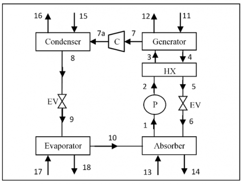
In this study, a small compressor is suggested to be installed between the steam generator and the condenser at point 7 which is the outlet of steam from the generator as shown in Figure 2. This position will allow us to reduce the operation temperature of the cycle. Hence, the new configuration of the absorption chiller will work on low-grade temperature heat source such as solar energy.
Figure 2 explains the location of the suggested compressor in a single effect absorption chiller. From the thermodynamic principles, water boils and evaporates at a temperature of 100℃ and pressure of 1 atm. If there is a way to reduce the pressure in the steam generator below 1 atm. (vacuum), the water evaporates at lower than 100℃ and this phenomenon allows water to evaporate at waste heat where low grade temperature heat source is available. On the other hand, increasing pressure in the condenser will lead to an increase in the condensation rate which means decreasing the heat losses or increasing the performance of the cycle. This work will allow to use the single effect chiller based on waste heat resources such as the ICE exhaust or the fuel cells or solar energy. It will contribute in providing a pollutionless environment.
(a)
(b)
(c)
Figure 1. Multi-effect Absorption chillers: a) Single, b) Double and c) Triple
Figure 2. The suggested location of the compressor
Based on the mass and energy balance principle in addition to the application of the laws of thermodynamics, an analysis has been carried out on each component of the suggestion configuration in Figure 2. There are some assumptions adopted in this analysis:
1. Whole cycle should operate at steady state conditions.
2. Pure refrigerant flows through the suggested compressor, condenser, and evaporator, while the solution of the refrigerant-absorbent flows through a pump, steam generator, and absorber.
3. Losses in pressure via friction, acceleration, and elevation will be ignored throughout the operation.
4. Fluids specific heat values are constants throughout the operation.
5. Is-enthalpy cross the expansion valves.
6. Is-entropy process happened through pumps and compressor.
In this study, a computer code has been written using Mat-lab incorporated with subroutines of thermos-physical properties calculations of the pure and/or the aqueous solution which are available in the literature [30, 31].
To optimize the new modification, some design parameters should be enhanced. These parameters are used for the comparison purpose between the absorption chillers before and after the modification. These parameters are:
3.1 Coefficient of performance (COP)
It is the most attractive parameter to select a chiller. The highest values represent the best operation of a cycle. It can be calculated from
$C O P=\frac{Q_{e v a p}}{Q_{g e n}+W_p+W_C}$ (1)
3.2 Generator temperature (Tgen)
It should be low enough to validate the new configuration to work based on low temperature heat source so that the lowest generator temperature is desired.
3.3 Circulation ratio (Cr)
It is defined as the ratio between the solution mass flow rate of the absorber outlet and the total refrigerant mass flow rate of the total system. Lowering this ratio is desirable [32]. It is found from:
$C_r=\frac{m_{a b s}}{m_{r e f}}$ (2)
According to Figure 2, the analysis of mass and energy balance for each component has adopted with thermodynamics laws starting from point 1 to point 19 as follows:
4.1 Centrifugal pump (P)
At point 1, the weak solution of the LiBr-water enters the pump, and exits at point 2. The analysis of the pump is:
$\dot{m}_1=\dot{m}_2=\dot{m}_{\text {ref }}$ (3)
$W_p=\dot{m}_{r e f}\left(h_2-h_1\right)$ (4)
4.2 Solution heat exchanger (SHX)
The idea of using the heat exchanger in this cycle is to avoid the irreversibility effects which could be happened in the generator at high temperature. SHX can cool down the hot concentrated solution that comes from the generator at point 4 and make it suitable to enter the expansion valve later at section 4.5. The analysis of SHX is:
$\dot{m}_2=\dot{m}_3, \dot{m}_4=\dot{m}_5$ (5)
$C_{\text {hot }}\left(T_4-T_5\right)=\dot{m}_S\left(h_4-h_5\right)$ (6)
$C_{\text {cold }} \cdot\left(T_3-T_2\right)=\dot{m}_w \cdot\left(h_3-h_2\right)$ (7)
$Q_{h x}=\dot{m}_w\left(h_3-h_2\right)=\dot{m}_s\left(h_4-h_5\right)$ (8)
The solution heat exchanger's effectiveness
$\varepsilon_{s h x}=\frac{Q_{a c t}}{\dot{Q}_{\max }}=\frac{\left(h_4-h_5\right)}{\left(h_4-h_2\right)}=\frac{\left(T_4-T_5\right)}{\left(T_4-T_2\right)}$ (9)
4.3 Solution expansion valve (SEV)
The cold down concentrated solution exits the SEV at point 6. The pressure will be reduced to be suitable for absorber component operation. The analysis of the SEV is:
$\dot{m}_5=\dot{m}_6$ (10)
$h_5=h_6$ (11)
4.4 The steam generator (G)
Steam leaves the generator at point 7 to enter the suggested compressor. Moreover, reducing of water content in the solution of LiBr-H2O, will lead to produce a strong solution which leaves the generator at point 4 as stated before. The mass and energy balances across the generator are given by:
$\dot{m}_3=\dot{m}_7+\dot{m}_4$ (12)
$Q_{g e n}+\dot{m}_3 h_3=\dot{m}_7 h_7+\dot{m}_4 h_4$ (13)
4.5 The suggested compressor (C)
The steam leaves the generator and enters the compressor at point 7 while it leaves the compressor at point 7a as shown in Figure 2. The process within the compressor is isentropic and the analysis will be similar to the analysis of the pump because of the same working in increasing the pressure of the fluid.
$\dot{\mathrm{m}}_{7 \mathrm{a}}=\dot{\mathrm{m}}_7$ (14)
$W_c=\dot{m}_{7 a}\left(h_{7 a}-h_7\right)$ (15)
4.6 The condenser
The steam, which comes from the compressor at high pressure, enters the condenser at point 7a as shown in Figure 2, the condensed water leaves the condenser at point 8. The analysis of the condenser is:
$\dot{m}_8=\dot{m}_7$ (16)
$Q_{\text {cond }}=\dot{m}_7\left(h_7-h_8\right)$ (17)
4.7 Refrigerant expansion valve (REV)
The condensed pressurized water flows through REV at point 8 and left it at point 9 through isenthalpic process.
$\dot{m}_8=\dot{m}_9$ (18)
$h_8=h_9$ (19)
4.8 The evaporator
The condensed pressurized water will expand through the REV, the low pressure water enters the evaporator at point 9 and leave at point 10. The evaporator is useful for absorbing the heat from the space to be cooled (cooling load) and uses the incoming energy to evaporate the low pressure water in order to generate steam at point 10 to be absorbed finally by the strong solution of the LiBr-H2O in the absorber to restart a new cycle at point 1. The analysis of the evaporator is:
$\dot{m}_9=\dot{\mathrm{m}}_{10}$ (20)
$\mathrm{Q}_{\mathrm{evap}}=\dot{\mathrm{m}}_{10}\left(\mathrm{~h}_{10}-\mathrm{h}_9\right)$ (21)
5.1 Log-mean and effectiveness models
These models have been applied for each component except the pump, compressor, and expansion valve where heating or cooling in this equipment is negligible as shown in Figure 2. These models are formulated based on the heat exchanger as follows [33]:
$Q=U \times A \times \Delta \theta$ (22)
$L M T D=\frac{\Delta T_2-\Delta T_1}{\log \left(\Delta T_2 / \Delta T_1\right)}$ (23)
where, $\Delta T_1$ and $\Delta T_2$ are the temperature difference between the two ports of the first side and second sides of the component respectively.
$R=\frac{\left(T_{\text {in }}-T_{\text {out }}\right)_{\text {hot }}}{\left(T_{\text {out }}-T_{\text {in }}\right)_{\text {cold }}}$ (24)
$\varepsilon=\frac{\varepsilon_o}{n-\varepsilon_o(n-1)}$ for $R=1$ (25)
$\varepsilon=\frac{1-X^{1 / n}}{R-X^{1 / n}} \quad$ for $R \neq 1$ (26)
where, $X=R \varepsilon_o-1 / \varepsilon_o-1, \mathrm{n}$ is number of shells, and $\varepsilon_o=$ $\left(T_{\text {out }}-T_{\text {in }}\right)_{\text {cold }} /\left(T_{\text {hot }}\right)_{\text {in }}-\left(T_{\text {cold }}\right)_{\text {in }}$.
$\Delta \theta=F_c \times L M T D$ (27)
where, $F_c=\left(\sqrt{R^2+1} \ln \frac{1-\varepsilon}{1-R \varepsilon}\right) /\left((R-1) \operatorname{Ln} \frac{2-\varepsilon\left(R+1-\sqrt{R^2+1}\right)}{2-\varepsilon\left(R+1+\sqrt{R^2+1}\right)}\right)$.
5.2 External energy balance and effectiveness
This balance is placed on thermodynamics law application of each stream of heating or cooling devices as shown in Figure 2.
For the steam generator:
$Q_{g e n}=\dot{m}_{11}\left(h_{11}-h_{12}\right)$ (28)
$\varepsilon_{\text {gen }}=\left(T_{11}-T_{12}\right) /\left(T_{11}-T_7\right)$ (29)
For the absorber
$Q_{a b s}=\dot{m}_{13}\left(h_{14}-h_{13}\right)$ (30)
$\varepsilon_{a b s}=\left(T_{14}-T_{13}\right) /\left(T_6-T_{13}\right)$ (31)
For the condenser
$Q_{\text {cond }}=\dot{m}_{15}\left(h_{16}-h_{15}\right)$ (32)
$\varepsilon_{\text {cond }}=\left(T_{15}-T_{16}\right) /\left(T_{15}-T_8\right)$ (33)
For the evaporator
$Q_{\text {evap }}=\dot{m}_{17}\left(h_{17}-h_{18}\right)$ (34)
$\varepsilon_{e v a p}=\left(T_{17}-T_{18}\right) /\left(T_{17}-T_{10}\right)$ (35)
5.3 Thermo-physical properties
LiBr-H2O solution and H2O thermos-physical properties could be estimated using experimental data for each property with accurate equations. These equations are displayed in details in the literature [30].
Since little information about using the compressor to improve the single effect absorption chiller is available in the literature [34], two steps have been followed for the validation of the current study. The first step, the single effect absorption chiller before adding the compressor, which is shown in Figure 1a, has been analyzed using mass and energy balance. The results of this cycle have compared with the similar cycle displayed by Herold et al. [4] as shown in Table 1.
Table 1 shows an acceptable difference between the numerical output results of the current study and the results of Herold et al. [4] study. The second step of the validation procedure is adding the compressor and the new cycle results are displayed tabular and graphically as shown in the next section.
Mass and energy balance in addition to thermodynamics laws have been adopted in the analysis of the suggested compressor aid absorption cycle. The primary operation conditions of the single effect chiller adopted in the current work are shown in Table 2.
Adding a small compressor between the generator and the condenser will improve the performance of the original cycle in terms of enhancing three main parameters including: the heat capacity of the evaporator (Qevap), the generator temperature (Tgen), and the overall coefficient of performance (COP).
Table 3 showed these three parameters in a comparison between the original cycle before and after adding the compressor according to Figure 2.
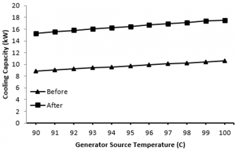
Table 3 shows a comparison between the new cycle configuration results and the original one. The results indicate the comprehensive improvement of the main parameters (Tgen, Qevap, and COP). The temperature of the operation has been reduced from 100℃ to 90℃ while the cooling capacity or the evaporator heat capacity increased from 10.58 kW to 15.28 kW and lastly, the COP enhanced from 0.721 to 0.803. The description of these behaviors is graphically shown in Figure 3 and Figure 4. Setting up a compressor with a compression ratio of 1.873 between the generator and the condenser leads to a decrease in the pressure of the generator which causes increasing the steam rate of evaporation and a decrease in the operating temperature. On the other hand, the compressor increases the condenser pressure which means increasing the condensation rate and releasing more heat which leads to improve the coefficient of performance as a result of increasing the evaporator heat transfer capacity as shown in Figure 4. The analysis of the new cycle showed that the circulation ratio decreases from 0.9095 to 0.865 and this is desirable for good design. Mohammed [27] stated that the range of the generator temperature is 90℃ - 120℃ as a good choice in the analysis of the single effect absorption chiller. However, Herold et al. [4] showed that increasing the temperature of the generator above 100℃ probably leads to crystallization risk. In this study, a range of 90℃-100℃ is adopted to meet the safe range of both studies [4, 27] as shown in Figure 3 to Figure 5.
Figure 3 shows the effect of generator temperature on the cooling capacity (Qevap) for both cases: before and after adding the compressor. It observed a big difference between the two cases and both behaviors are proportional directly to the generator temperature.
Figure 4 showed that the effect of Tgen on the COP before and after adding the compressor. It is clear that the effect is slight in the original chiller while the effect could be recognized after adding the compressor and this behavior is agreed with the results of the study [19].
Table 1. The results of the comparison between the current study and Herold et al. [4]
|
Properties |
Herold et al. [4] |
The current study |
Difference |
|
T1 (℃) |
32.72 |
32.91 |
-0.190 |
|
T2 (℃) |
32.72 |
32.91 |
-0.190 |
|
T3 (℃) |
63.61 |
63.20 |
0.410 |
|
T4 (℃) |
89.36 |
89.41 |
-0.050 |
|
T5 (℃) |
53.11 |
53.25 |
-0.140 |
|
T6 (℃) |
44.96 |
44.68 |
0.280 |
|
T7 (℃) |
76.76 |
76.82 |
-0.060 |
|
T8 (℃) |
40.06 |
39.93 |
0.130 |
|
T9 (℃) |
1.39 |
1.465 |
-0.080 |
|
T10 (℃) |
1.39 |
1.465 |
-0.080 |
|
Tgen (℃) |
100 |
100 |
0 |
|
HCgen (kW) |
14.73 |
14.67 |
0.060 |
|
HCabs (kW) |
14.09 |
14.04 |
0.050 |
|
HCcond (kW) |
11.31 |
11.21 |
0.100 |
|
HCevap (kW) |
10.67 |
10.58 |
0.090 |
|
HCSHX (kW) |
3.105 |
3.060 |
0.045 |
|
COP |
0.724 |
0.721 |
0.003 |
Table 2. Primary operation conditions
|
The property |
The magnitude |
|
$\dot{\mathrm{m}}_{\mathrm{ref}}$ (kg/s) |
0.05 |
|
εHX (-) |
0.64 |
|
UAgen (kW/K) |
1.20 |
|
UAabs (kW/K) |
1.80 |
|
UAcond (kW/K) |
1.40 |
|
UAevap (kW/K) |
2.50 |
|
HCSHX (kW) |
3.11 |
Table 3. The results of the chiller before and after adding the compressor
|
Property |
Before adding |
After adding |
|
T1 (℃) |
32.91 |
32.71 |
|
T2 (℃) |
32.91 |
32.71 |
|
T3 (℃) |
63.20 |
57.53 |
|
T4 (℃) |
89.41 |
80.92 |
|
T5 (℃) |
53.25 |
50.07 |
|
T6 (℃) |
44.68 |
44.18 |
|
T7 (℃) |
76.82 |
51.05 |
|
T7a (℃) |
- |
51.12 |
|
T8 (℃) |
39.93 |
64.39 |
|
T9 (℃) |
1.465 |
17.97 |
|
T10 (℃) |
1.465 |
17.97 |
|
Tgen (℃) |
100.0 |
90.00 |
|
HCevap (kW) |
10.58 |
15.28 |
|
COP |
0.721 |
0.803 |
Figure 3. The influence of generator source temperature on the cooling capacity
Figure 4. The influence of generator source temperature on the coefficient of performance
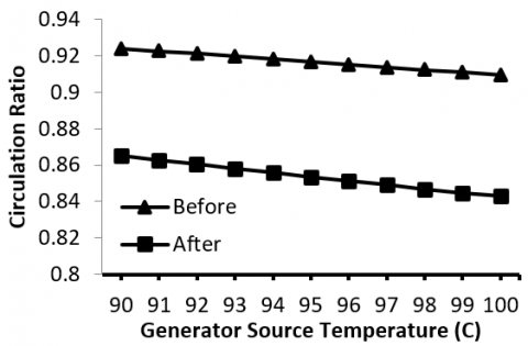
Figure 5. The influence of generator source temperature on the system circulation ratio
Figure 5 shows the effect of the generator temperature on the circulation ratio. It is clear from the figure that the circulation decreases as the temperature increase and this behavior is agreed with the literature [32, 35, 36].
Waste heat such as solar energy is the free energy that should be used to provide a natural source of energy that can be used to operate the refrigeration units without harming the environment. The absorption chiller represents a clean environmental solution. Many types of absorption chillers are available in the literature and the single effect chiller represents the most attractive one. It requires some modifications to increase its performance and reduce the operating temperature with no or minimal change in other important factors such as the cost and size. After an intensive search in the literature and according to the author's knowledge, there is no clear study available has been published about achieving these goals except a few works in a different conditions from the original cycles which are available in the literature. In this study, a small steam compressor is suggested to be set up between the generator and the condenser.
The results of the suggested form of the single effect absorption chiller showed the following:
1. The operation temperature of the cycle has been reduced from 100℃ to 90℃. This result will emphasize using the suggested cycle based on a waste heat source such as solar energy soource.
2. The cooling capacity increased from 10.575 kW to 15.278 kW which makes the cycle convenient for countries with hot weather. and
3. The performance increased from 0.721 to 0.803 which leads to the use of most of the input waste heat
4. The new cycle will be Slightly expensive, and bigger in size when the compression ratio of the compressor is 1.873 only. However, this increment is negligible compared to the above modification
These results represent better modifications compared to the literature and especially when improving the operation temperature, the cooling capacity, and the performance in the same work.
The author is appreciated to Washington State University through the non-valuable guide of Prof. Dr. Cill Richards. Thanks to the Ministry of Higher Education and Scientific Research through The University of Babylon for the full financial support. Too many thanks to those who supported this work especially Ms. Layla Naji and Mrs. Asawer Majeed for their supporting me throughout each step of this study.
|
Scripts |
|
|
LiBr |
Lithium Bromide salt |
|
VCPP |
Vapor compression power plant |
|
EV |
Expansive valve |
|
REV |
Refrigerant expansion valve |
|
SEV |
Solution expansion valve |
|
HX |
Heat exchanger |
|
SHX |
Solution heat exchanger |
|
Q |
Heat transfer (kW) |
|
Cr |
Circulation ratio (-) |
|
T |
Temperature (℃) |
|
M |
Mass flow rate (kg/s) |
|
W |
Work (Watt) |
|
h |
Enthalpy (kJ/kg) |
|
U |
Overall heat transfer coefficient (w/m2. ℃) |
|
Δθ |
Overall heat transfer temperature (℃) |
|
ε |
Effectiveness (-) |
|
HC |
Heat capacity (KW) |
|
Subscripts |
|
|
evap |
Evaporator |
|
gen |
Generator |
|
cond |
Condenser |
|
abs |
Absorber |
|
p |
Pump |
|
c |
Compressor |
|
act |
Actual |
|
maxi |
Maximum |
|
ref |
reference |
[1] Misra, R.D., Sahoo, P.K., Gupta, A. (2006). Thermoeconomic evaluation and optimization of an aqua-ammonia vapour-absorption refrigeration system. International Journal of Refrigeration, 29(1): 47-59. https://doi.org/10.1016/j.ijrefrig.2005.05.015
[2] Talpada, J.S., Ramana, P.V. (2019). A review on performance improvement of an absorption refrigeration system by modification of basic cycle. International Journal of Ambient Energy, 40(6): 661-673. https://doi.org/10.1080/01430750.2017.1423379
[3] Azhar, M., Siddiqui, M.A. (2019). Exergy analysis of single to triple effect lithium bromide-water vapour absorption cycles and optimization of the operating parameters. Energy Conversion and Management, 180: 1225-1246. https://doi.org/10.1016/j.enconman.2018.11.062
[4] Herold, K.E., Radermacher, R., Klein, S.A. (2016). Absorption Chillers and Heat Pumps. CRC Press.
[5] Nikbakhti, R., Wang, X., Hussein, A.K., Iranmanesh, A. (2020). Absorption cooling systems–Review of various techniques for energy performance enhancement. Alexandria Engineering Journal, 59(2): 707-738. https://doi.org/10.1016/j.aej.2020.01.036
[6] Gebreslassie, B.H., Medrano, M., Boer, D. (2010). Exergy analysis of multi-effect water–LiBr absorption systems: From half to triple effect. Renewable Energy, 35(8): 1773-1782. https://doi.org/10.1016/j.renene.2010.01.009
[7] Absorption Chiller Market Research, In-depth analysis which provides critical revenue and estimates for the period 2022 To 2028 based on Type and Applications. https://www.alliedmarketresearch.com/absorption-chillers-market, accessed on 13 April 2023.
[8] Xu, Z.Y., Wang, R.Z. (2016). Absorption refrigeration cycles: Categorized based on the cycle construction. International Journal of Refrigeration, 62: 114-136. https://doi.org/10.1016/j.ijrefrig.2015.10.007
[9] Souri, K., Kashyzadeh, K.R., Naghdali, A.S., Mesbah, M. (2020). Performance of a single effect absorbing chiller lithium bromide-water coupled to a solar collector. In Journal of Physics: Conference Series, 1687(1): 012026. https://doi.org/10.1088/1742-6596/1687/1/012026
[10] Lahoud, C., El Brouche, M., Lahoud, C., Hmadi, M. (2021). A review of single-effect solar absorption chillers and its perspective on Lebanese case. Energy Reports, 7: 12-22. https://doi.org/10.1016/j.egyr.2021.09.052
[11] Al-Yasiri, Q., Szabo, M., Arıcı, M. (2022). A review on solar-powered cooling and air-conditioning systems for building applications. Energy Reports, 8: 2888-2907. https://doi.org/10.1016/j.egyr.2022.01.172
[12] Cascetta, F., Cirillo, L., Della Corte, A., Nardini, S. (2017). Comparison between different solar cooling thermally driven system solutions for an office building in Mediterranean Area. International Journal of Heat and Technology, 35(1): 130-138 https://doi.org/10.18280/ijht.350118
[13] Gomri, R. (2013). Simulation study on the performance of solar/natural gas absorption cooling chillers. Energy Conversion and Management, 65: 675-681. https://doi.org/10.1016/j.enconman.2011.10.030
[14] Yosaf, S., Ozcan, H. (2019). Effect of ejector location in absorption refrigeration cycles using different binary working fluids. International Journal of Air-Conditioning and Refrigeration, 27(1): 1950003. https://doi.org/10.1142/S2010132519500032
[15] Mejbri, K., Bellagi, A. (2018). Modeling of the thermodynamic properties of the methylamine/water refrigerant mixture. International Journal of Petrochemical Science & Engineering, 3(4): 161-170. https://doi.org/10.15406/ipcse.2018.03.00090
[16] Dewan, A., Mahanta, P., Raju, K.S., Kumar, P.S. (2004). Review of passive heat transfer augmentation techniques. Proceedings of the Institution of Mechanical Engineers, Part A: Journal of Power and Energy, 218(7): 509-527. https://doi.org/10.1243/0957650042456953
[17] Benramdane, M., Ghernaouet, M.E.A., Abboudi, S. (2014). Contribution to Improving the Performance Coefficient of a Solar Absorption Refrigeration System. International Journal of Research and Reviews in Applied Sciences, 21(2): 71-81.
[18] Lubis, A., Jeong, J., Giannetti, N., Yamaguchi, S., Saito, K., Yabase, H., Alhamid, M.I. (2018). Operation performance enhancement of single-double-effect absorption chiller. Applied Energy, 219: 299-311. https://doi.org/10.1016/j.apenergy.2018.03.046
[19] Riffat, S.B., Wong, C.W. (1994). Gas-driven absorption/recompression system. Heat Recovery Systems and CHP, 14(2): 165-171. https://doi.org/10.1016/0890-4332(94)90007-8
[20] Jain, V., Sachdeva, G., Kachhwaha, S.S. (2021). Thermodynamic analysis of ejector-assisted vapour compression–absorption hybrid refrigeration system. International Journal of Ambient Energy, 42(5): 576-585. https://doi.org/10.1080/01430750.2018.1562972
[21] Ullah, K.R., Saidur, R., Ping, H.W., Akikur, R.K., Shuvo, N.H. (2013). A review of solar thermal refrigeration and cooling methods. Renewable and Sustainable Energy Reviews, 24: 499-513. https://doi.org/10.1016/j.rser.2013.03.024
[22] Gao, Y., He, G., Chen, P., Zhao, X., Cai, D. (2019). Energy and exergy analysis of an air-cooled waste heat-driven absorption refrigeration cycle using R290/oil as working fluid. Energy, 173: 820-832. https://doi.org/10.1016/j.energy.2019.02.117
[23] Arshi, B.P.S., Sudharsan, N.M. (2017). Feasibility studies of single-effect H2O-LiBr+LiI+LiNO3+LiCl vapour absorption cooling system for solar based applications. Journal of Chemical and Pharmaceutical Sciences, 12: 1-7.
[24] Wang, S., Li, S., Xu, M., Jin, Z., Xu, C. (2022). Simulation research on absorption refrigeration system based on NH3-H2O-LiBr vapor-liquid equilibrium calculation model. Thermal Science, 26(2 Part C): 1825-1840. https://doi.org/10.2298/TSCI210127201W
[25] Olbricht, M., Lonardi, F., Luke, A. (2018). Performance improvement of absorption chillers by means of additives–A numerical study. Solar Energy, 166: 138-145. https://doi.org/10.1016/j.solener.2018.03.048
[26] Kilic, B., Ipek, O. (2022). Thermodynamic analysis of absorption cooling system with LiBr-Al2O3/water nanofluid using solar energy. Thermal Science, 26(1 Part A): 135-146. https://doi.org/10.2298/TSCI200817340K
[27] Mohammed, Y.A. (2020). Parametric study of a single effect lithium bromide-water absorption cooling system powered by a waste heat from diesel engine. Ph. D. thesis, Red Sea University, Portsudan.
[28] Schmid, F., Bierling, B., Spindler, K. (2019). Development of a solar-driven diffusion absorption chiller. Solar Energy, 177: 483-493. https://doi.org/10.1016/j.solener.2018.11.040
[29] Selvaraj, D.A., Nadimuthu, L.P.R., Victor, K. (2022). Monitoring and simulation of parabolic trough collector powered vapor absorption refrigeration system for rural cold storage. Thermal Science, 26(2 Part A): 975-982. https://doi.org/10.2298/TSCI201110298S
[30] Florides, G.A., Kalogirou, S.A., Tassou, S.A., Wrobel, L.C. (2003). Design and construction of a LiBr–water absorption machine. Energy Conversion and Management, 44(15): 2483-2508. https://doi.org/10.1016/S0196-8904(03)00006-2
[31] Manu, S., Chandrashekar, T.K. (2016). A simulation study on performance evaluation of single-stage LiBr–H2O vapor absorption heat pump for chip cooling. International Journal of Sustainable Built Environment, 5(2): 370-386. https://doi.org/10.1016/j.ijsbe.2016.08.002
[32] Cimsit, C., Ozturk, I.T. (2012). Analysis of compression–absorption cascade refrigeration cycles. Applied Thermal Engineering, 40: 311-317. https://doi.org/10.1016/j.applthermaleng.2012.02.035
[33] Heat Exchangers, Types and it Efficiency, https://energyxchangeml.wordpress.com/tag/heat-exchanger-efficiency, accessed on 7 Nov 2022.
[34] Chawla, A. (2014). Compressor assisted air-cooled single effect absorption chiller. Doctoral dissertation, Washington State University.
[35] Modi, B., Mudgal, A., Patel, B. (2017). Energy and exergy investigation of small capacity single effect lithium bromide absorption refrigeration system. Energy Procedia, 109: 203-210. https://doi.org/10.1016/j.egypro.2017.03.040
[36] Rasheed Al-Amir, Q., Kadhem Hamzah, H., S Al-turaihi, R. (2017). Performance assessment of LiBr-H2O absorption chiller for air conditioning purposes. Journal of Kerbala University, 13(3): 160-173.