Shuaibing Chang![]()
© 2023 IIETA. This article is published by IIETA and is licensed under the CC BY 4.0 license (http://creativecommons.org/licenses/by/4.0/).
OPEN ACCESS
Ionic wind is a phenomenon of electrofluid movement in electrostatic precipitator, which changes the motion state of flue gas and dust in electrostatic precipitator to a certain extent. In order to study the influence of ionic wind on air flow characteristics in electrostatic precipitator, this paper constructed a numerical model of electric field-flow field coupling and compared the impact of electro-hydro dynamics (EHD) effect on flue gas flow state at different inlet velocities. In addition, this paper analyzed the influence of EHD effect on the motion trajectories of particles with different sizes. The results showed that the EHD effect changed the flue gas flow field near the anode plate at 0.3m/s inlet velocity, forming an obvious reflux region; this phenomenon weakened when the inlet velocity increased. At the same time, the EHD effect reduced the dust removal efficiency when the particle radius ranged from 0.25 μm to 1 μm.
high voltage ionization, electrohydrodynamics, electrostatic precipitator, ionic wind, multi-physical field numerical analysis
As a common dust removal equipment, electrostatic precipitator is often used in the smoke and dust treatment process in the energy production process. Its performance directly affects the environmental protection performance of the production system. The flow state in the electrostatic precipitator determines the residence time of dust particles in the precipitator, thus affecting the dust removal efficiency. However, the electrostatic precipitator generates ionic wind, which makes the flow law of working medium more complex. At the same time, the ionic wind also affects the flow field and particle movement in the precipitator [1-3]. The formation of ionic wind is mainly related to ionic migration. The gas molecules in the electric field space are ionized to form charged ions, which migrate under the action of the electric field force. During the migration process, they interact with air molecules, which causes air flow within the region, thus forming the ionic wind phenomenon [4-7]. In 1709, the phenomenon of ionic wind was first reported. Robinson [8] began to study the phenomenon of ionic wind systematically for the first time till 1961. Up to now, ionic wind produced by corona discharge has been studied in many fields. Because ionic wind has obvious influence on the removal process of particles in electrostatic precipitator, extensive research on ionic wind has been done in environmental protection [9-12]. Zhou et al. [13] put forward the famous Deutsch formula without considering the change of particle driving speed caused by ionic wind. This formula shows that the efficiency of electrostatic precipitator is directly proportional to the particle driving speed and the area of the dust collecting plate, and inversely proportional to the gas flow rate. Liu et al. [14] used experimental and numerical simulation methods to study the effect of different types of expansion and contraction spoiler (ECS) arrangement on the distribution of electric field intensity, flow velocity, particle motion pattern and dust removal efficiency. The results showed that ECS structure formed vortex with low speed and increased the retention time of dust particles, thus obviously improving the dust removal efficiency. Lee et al. [15] studied the effects of the geometric parameters of tubular discharge electrode, such as line length, line spacing and line bending angle, on the collection efficiency by numerical analysis. The results showed the effect of optimized discharge electrode on dust removal power consumption and ozone amount was not obvious, but the improvement of electrode structure increased the dust removal efficiency of electrostatic precipitator by about 15%. Liu et al. [16] calculated the electric field of the wire plate channel by the finite volume method, and simulated the airflow of the electrostatic precipitator as a whole. Kim et al. [17] built a numerical model of line-plate electrostatic precipitator, and verified its rationality by comparing the experimental results. Long and Yao [18] built a numerical model of the charging process of nine kinds of particles, and compared the influence of different charging models on the particle motion in the line-plate electrostatic precipitator. The experimental results found that the prediction results of the unsteady charge model were significantly lower than that of the constant charge model.
To sum up, the current studies on the flow characteristics in electrostatic precipitator have mostly focused on the influence of factors, such as the difference of electrostatic precipitator structure and electric field intensity, on the flow characteristics. Few research has studied the impact of the difference in air inlet velocity on the ionic air in the precipitator and the particle charge, which is very important for optimizing the operation parameters of the precipitator. Therefore, this paper constructed a multi-physical field coupling simulation model, and analyzed the influence of the initial value of the inlet air flow on the internal gas-solid two-phase flow characteristics, which provided a theoretical reference for further optimizing the operating parameters of electrostatic precipitator.
Figure 1. Structure of line-plate electrostatic precipitator
The research object of this paper was line-plate electrostatic precipitator (Figure 1), which was composed of three cathode lines and two anode plates. One of the anode plate was grounded and its loading voltage was 20kV. The distance from cathode line to anode plate was 0.05m, and that between adjacent cathode lines was 0.15m. The length of anode plate in the calculation area was 0.7m. The electrostatic precipitator was flue gas.
The cathode line voltage was high during the working process of electrostatic precipitator. Therefore, a non-uniform electric field formed in the dust removal channel, with large field strength near the cathode line [19]. The discharge area formed and the flue gas was ionized. Particles were charged after passing through the discharge zone. The above process involved many physical processes, such as electrostatic field, ionic migration and fluid and particle motion, which increased the difficulty of building the numerical model. In order to simplify the model, this paper ignored the influence of charge carried by particles on the intensity of space electric field. By constructing the numerical model of coupling fluid and discharge, a simplified corona model in the electrostatic precipitator was obtained. The charge conservation equation and Poisson equation were used to solve the carrier transport problem. The specific equations were as follows:
$\nabla \bullet J=0$ (1)
$J={{z}_{q}}{{\mu }_{q}}{{\rho }_{q}}E+\rho u$ (2)
${{\varepsilon }_{0}}{{\nabla }^{2}}V=-{{\rho }_{q}}$ (3)
where, J is the current density per unit area in the calculation domain, with A/m2 as its unit; μq is the charge mobility, with m2/V·s as its unit; Zq is the charge number of the working medium; ρq is the space charge number density, with C/m3 as its unit; E is the electric field intensity, with V/m as its unit; u is the fluid velocity, with m/s as its unit; V is the voltage value, with V as its unit; and ε0 is the vacuum dielectric constant. The transport equation was as follows:
$\mu \left( \frac{\rho _{q}^{2}}{{{\varepsilon }_{0}}}-\nabla V\bullet \nabla {{\rho }_{q}} \right)+\nabla {{\rho }_{q}}\bullet u=0$ (4)
In order to simplify the calculation model, the paper assumed that the ionic mobility was constant and ignored the plasma process during flue gas ionization in the electrostatic precipitator. For the corona electrode, the electric field component was defined as:
$n\bullet E={{E}_{0}}$ (5)
To determine whether the discharge electrode met the corona occurrence conditions, Peake's law was introduced into the model to determine the electric field intensity when corona occurred:
${{E}_{0}}=3\times {{10}^{6}}\delta \left( 1+\frac{0.03}{\sqrt{\delta {{r}_{i}}}} \right)$ (6)
where, δ is the density of ionization medium, with kg/m3 as its unit; ri is the radius of the corona electrode, with m as its unit.
The flow state of ionized flue gas in the electrostatic precipitator was regarded as the effect of electric field force on the working fluid, which made the working fluid in the precipitator show the characteristics of charged fluid, which is called EHD effect. Therefore, the working fluid flow process was described as follows:
$\rho (u\cdot \nabla )u=\nabla \cdot \left[ -pI+\mu \left( \nabla u+{{(\nabla u)}^{T}} \right) \right]+{{F}_{EHD}}$ (7)
$\nabla \cdot u=0$ (8)
where, μ is the dynamic viscosity, with kg/(m·s) as its unit; ρ is the density of the fluid, with kg/m3 as its unit; p is pressure, with Pa as its unit; FEHD is the force of the electric field on the fluid, which was calculated as follows:
${{F}_{EHD}}={{\rho }_{q}}E$ (9)
This paper mainly studied the influence of EHD effect on the gas-solid two-phase flow law in electrostatic precipitator. Therefore, when the EHD effect was ignored, FEHD was 0. When EHD effect was considered, FEHD was calculated according to formula 9.
Because this paper focused on particle trajectory in electrostatic precipitator, and ignored the particle collision process, the particle motion process satisfied Newton's second law, which was described as follows:
$\frac{dq}{dt}=v$ (10)
$\frac{d}{dt}\left( {{m}_{p}}v \right)={{F}_{t}}$ (11)
where, q is the corresponding position of particles in the dust collector, with m as its unit; v is the particle movement speed in the dust collector, with m/s as its unit; mp is the mass of a single dust particle, with kg as its unit; and Ft is the sum of forces exerted on particles, with N as its unit. Because the particle radius became very small, the rarefaction effect needed to be included in the drag force FD, which was described by the Cunningham-Millikan-Davis [20] model as follows:
${{F}_{D}}=\frac{1}{{{\tau }_{p}}S}{{m}_{p}}(u-v)$ (12)
where, τp is the response time of particle motion state, with s as its unit, which was defined as follows:
${{\tau }_{p}}=\frac{4{{\rho }_{p}}d_{p}^{2}}{3\mu {{C}_{D}}\operatorname{Re}x}$ (13)
where, ρp is the dust particle density in the electrostatic precipitator, with kg/m3 as its unit; dp is the size of dust particles, with m as its unit; CD is the coefficient of the particle subjected to the fluid drag force, and Rex is the relative Reynolds number given by the following formula:
${{\operatorname{Re}}_{x}}=\frac{\rho \|u-v\|{{d}_{p}}}{\mu }$ (14)
S is the drag correction coefficient, which was described as:
$S=1+Kn\left( 2.514+0.8\exp \left( -\frac{0.8}{Kn} \right) \right)$ (15)
where, Kn is a dimensionless coefficient.
Due to non-uniform electric field in the electrostatic precipitator, the particles were affected by the electric field force in the movement process. The force equation was described as follows:
${{F}_{e}}=eZE$ (16)
where, e is the elemental charge and Z is the number of cumulative charges on each particle. Accumulated charge on the particles was calculated using the Lawless [21] model, which was described as follows:
${{\tau }_{c}}\frac{dZ}{dt}=\left\{ \begin{array}{*{35}{l}} {{R}_{f}}+{{f}_{a}} & \left( \left| {{v}_{e}} \right|\le \left| {{v}_{s}} \right| \right) \\ {{R}_{d}}{{f}_{a}} & \left( \left| {{v}_{e}} \right|>\left| {{v}_{s}} \right| \right) \\\end{array} \right.$ (17)
where τc is the characteristic charging time, which was defined as follows:
${{\tau }_{c}}=\frac{{{e}^{2}}}{4\pi {{\rho }_{q}}\mu q{{\text{k}}_{B}}{{T}_{i}}}$ (18)
where, kB is Boltzmann constant and Ti is the space temperature in case of corona. The charging process of particles was divided into electric field charging and diffusion charging, and the corresponding charging rates were Rf and Rd, respectively, which were calculated using the following formula:
${{R}_{f}}=\frac{{{v}_{s}}}{4{{\varepsilon }_{0}}}{{\left( 1-\frac{{{v}_{e}}}{{{v}_{s}}} \right)}^{2}}$ (19)
${{R}_{d}}=\frac{{{v}_{e}}-{{v}_{s}}}{\exp \left( {{v}_{e}}-{{v}_{s}} \right)-1}$ (20)
where,
${{v}_{e}}=\frac{Z{{e}^{2}}}{4\pi {{\varepsilon }_{0}}{{r}_{p}}{{k}_{B}}{{T}_{i}}};{{v}_{s}}=3{{w}_{e}}\frac{{{\varepsilon }_{r,p}}}{{{\varepsilon }_{r,p+2}}} \ \ ;{{w}_{e}}=\frac{e{{r}_{p}}|E|}{{{k}_{B}}{{T}_{i}}}$ (21)
where, εr,p is the relative dielectric constant of the particles.
fa was a function that combined the diffusion charging rate with the electric field charging rate, which was defined as follows:
${{f}_{a}}=\left\{ \begin{array}{*{35}{l}} \frac{1}{{{\left( {{w}_{e}}+0.475 \right)}^{0.575}}} & \left( {{w}_{e}}\ge 0.525 \right) \\ 1 & \left( {{w}_{e}}<0.525 \right) \\\end{array} \right.$ (22)
3.1 Distribution of space charge density and electric field intensity
Figure 2. Distribution of space charge density and electric field
This paper mainly studied the influence of EHD effect on the flow characteristics of working fluid in electrostatic precipitator. Therefore, it was worth paying attention to whether the space charge density distribution was related to the air flow factor. Through calculation and comparison, it was found that the difference of inlet velocity and whether EHD effect was considered did not affect the distribution of space charge density, electric field intensity and the trend of electric field line. As shown in Figure 2, the space charge in electrostatic precipitator mainly concentrated in the discharge electrode. There was an obvious low charge region between the two cathodes, which reduced the charge probability of particles in this region. Combined with characteristics of the electric field line distribution, it was found that the distribution law of space charge was similar to that of electric field line, and it was considered that the space charge density was only affected by the electric field intensity and electrode parameters.
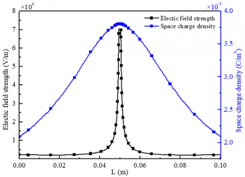
Figure 3. Distribution of space charge density and electric field intensity in the vertical direction of the electrode center
In order to explain the change of charge density and electric field intensity in the area near the electrode, this section extracted relevant data from the vertical centerline of the second electrode, as shown in Figure 3. The results showed that the electric field intensity suddenly increased in the area near the electrode, which was related to the electrode tip discharge phenomenon. The smaller the curvature diameter, the greater the electric field intensity. In addition, the electric field intensity outside the corona region was very small. The electric field intensity of a long distance was close to that of the anode plate, and the change rules of charge density and electric field intensity were different to some extent. In the vertical direction of the electrode center, although the charge density distribution rose from the anode plate to the cathode line, the increasing rate of charge density near the corona region was much lower than that of electric field intensity. It showed that the charge density was not obviously affected by the electric field intensity, which was related to the ionic diffusion process produced by ionization.
3.2 Influence of EHD effect on velocity field distribution in electrostatic precipitator
This paper ignored the ionization process of flue gas in electrostatic precipitator. The EHD effect was loaded into the calculation model as a volume force. The specific model was explained in formula 7. In order to further understand the impact of EHD effect on the flow field in electrostatic precipitator, this section compared the velocity field distribution before and after EHD effect was considered, as shown in Figure 4. The results showed when EHD effect was not considered, increasing the inlet velocity did not change the velocity field distribution and only affected the speed of each position in the precipitator. When the EHD effect was considered, the area of the low speed area near the anode plate increased in the vertical direction of the negative electrode, which changed the flue gas flow line near the anode plate in the precipitator, thus forming a local throttling and increasing the flue gas velocity in the central area. But this effect decreases along with the increase of inlet velocity.
Figure 4. Velocity field in electrostatic precipitator with different inlet velocities
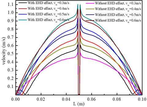
Figure 5. Velocity change in the vertical direction of electrode 1
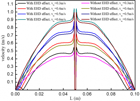
Figure 6. Velocity change in the vertical direction of electrode 2
Figure 7. Velocity change in the vertical direction of electrode 3
In order to further explore the degree of the EHD effect affected by the inlet velocity variation, this paper compared the velocity values in the vertical direction of each electrode center, as shown in Figure 5-Figure 7. The results showed that the velocity value near the electrode near the entrance was larger, because the boundary layer formed on the anode plate wall reduced the flue gas velocity. With the continuous development of flue gas flow, the closer to the outlet, the lower the flow velocity. When the EHD effect was not considered, the flue gas velocity always increased from small to large between the anode plate and the cathode line, and reached the peak near the cathode line, which did not change with the change of inlet velocity. When considering the EHD effect, although the peak velocity also appeared near the cathode line, multiple extreme velocity distribution showed at the current sampling position when the inlet velocity was between 0.3m/s-0.4m/s. According to Figure 4, when the inlet velocity was small, the EHD effect had an obvious effect on the streamline, with a small reflux region in the positive position of the cathode line. This phenomenon may affect the trajectory of particles, resulting in the secondary dust in the reflux region, which was further discussed later.
Figure 8. Velocity change in the horizontal direction near the anode plate (with EHD effect)
In Figure 4, it was found that when the EHD effect was taken into account, there was a low velocity zone near the anode plate; the low velocity zone at the positive position of the cathode line increased obviously and disturbance phenomenon occurred, which had a significant influence on the trajectory of particles near the wall. In order to deeply analyze the influence of inlet velocity fluctuation on the low velocity zone and reflux region near the anode plate, this paper compared four kinds of inlet velocity conditions. In the area near the anode plate (0.0475m from the anode plate), the velocity changed along the horizontal direction of the anode plate, as shown in Figure 8. The results showed that the velocity near the anode plate near the entrance was slightly higher than that near the inlet, because the velocity near the wall of the boundary layer was very low, which increased the velocity at other positions. In addition, the outlet velocity was higher than the inlet velocity at the same horizontal height, because of the fluctuating low velocity area between the anode plate and the electrode, which reduced the cross-sectional area and increased the inlet velocity. In the vicinity of the positive position of the cathode line, the velocity distribution showed a fluctuation pattern, and there was an obvious low velocity region. The smaller the inlet velocity, the larger the width of this area. At the same time, the velocity fluctuation occurred in this area. The smaller the inlet velocity, the more obvious the velocity fluctuation, which may reduce the dust capture efficiency in this area. With the increase of inlet velocity, the velocity fluctuation phenomenon in the low speed area gradually weakened, or even disappeared.
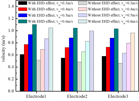
(a) Peak velocity
(b) Average velocity
Figure 9. Peak and average velocity in the vertical direction of each electrode
In order to further explore the influence of inlet velocity change on the EHD effect, the peak velocity and the average velocity in the vertical direction of each electrode center were compared, as shown in Figure 9. The results showed that the peak velocity near the cathode line decreased without considering the EHD effect. The lower the inlet velocity, the greater the decrease of the peak velocity near the cathode line. When the inlet flow rate was within the design scope of this paper, before and after considering the EHD effect, the peak velocity varied from 5.15% to 15.82% for the first electrode position, from 4.64% to 11.76% for the second, and from 6.89% to 20.23% for the third. At the same time, the average vertical velocity of each electrode also showed the above rule. When the inlet flow rate was within the design scope of this paper, the average vertical velocity varied from 3.37% to 12.52% for the first electrode, from 2.58% to 7.8% for the second, and from 3.81% to 13.62% for the third.
3.3 Influence of EHD effect on particle trajectory in electrostatic precipitator
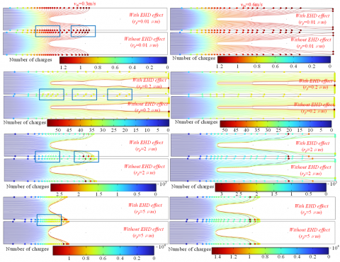
According to the conclusion in section 3.2, the EHD effect mainly affected the flow field near the anode plate. In order to explore whether the EHD effect affected the particle motion, this section compared the operation of particles with different sizes when the inlet flue gas velocity was 0.3m/s and 0.6m/s respectively, as shown in Figure 10. The results showed that when the inlet velocity was 0.3m/s, the particle motion near the wall was obviously affected by the EHD effect. At the positive position of the cathode line on the anode plate, the particles moved forward first and then backward. When the inlet velocity increased to 0.6m/s, this phenomenon became not obvious. According to formula 17-22, this phenomenon was related to the charging process of particles. In addition, according to the particle charging model, the cumulative charge of particles was related to the particle size. According to the results of Figure 10, when the radius of particles was 0.2 μm, the moving distance of the particles in the electrostatic precipitator was long, and it was not easy to be captured by the anode plate. At the same time, increasing the inlet flue gas flow rate also increased the moving distance of the particles in the electrostatic precipitator, thus reducing the dust removal efficiency.
The moving distance of particles was mainly affected by electric field force and smoke drag force, and the electric field force on particles was related to the cumulative charge of particles. In order to analyze the relationship between particle charge and size, this section calculated the cumulative charge of particles with different sizes moving to the anode plate or out of the calculation domain, as shown in Figure 11. The results showed that the cumulative charge of particles without considering EHD effect was significantly lower than that when EHD effect was considered. With the increase of particle size, the cumulative charge also increased. The larger the particle size, the more obvious the increase in charge.
Figure 10. Trajectory of charged particles
Figure 11. Accumulated charge number of particles with different sizes
3.4 Influence of EHD effect on dust collection efficiency of electrostatic precipitator
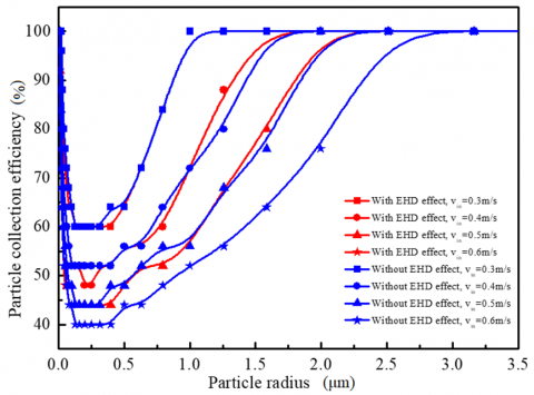
According to the working principle of electrostatic precipitator, the particle trajectory was directly related to the efficiency of precipitator. According to the results in Section 3.3, the particle trajectory was related to both particle size and particle charge. To reveal the relationship between EHD effect and the efficiency of electrostatic precipitator, this section collected the dust removal efficiency of different particle sizes in the electrostatic precipitator with different inlet velocities, as shown in Figure 12. Because the actual dust particle size distribution was complex, this paper only calculated the dedusting efficiency of limited particle sizes. In order to make the research results universal, the results in Figure 12 used the data fitting method to predict the corresponding dedusting efficiency of each particle size. The results showed that the current-size electrostatic precipitator had a low removal efficiency for particles with a radius of about 0.25 μm, with 40% as the lowest dust removal efficiency. When the particle radius was less than 0.25 μm, the collection efficiency of the electrostatic precipitator was not affected by the EHD effect. When the inlet velocity was 0.4m/s-0.5m/s, the EHD effect was beneficial to the removal of particles with a radius greater than 1 μm, but not conducive to the removal of small particles (0.25 μm-1 μm). However, with further improvement of the inlet flue gas speed, the impact of EHD effect on the dust removal efficiency became weaker and weaker, even could be ignored.
Figure 12. Collection efficiency of particles with different sizes
This paper studied the influence of EHD effect on flue gas flow in miniature electrostatic precipitator through numerical simulation, and compared the impact of EHD effect on flue gas flow and dust particles at different inlet velocities. The main conclusions were as follows:
(1) When the inlet velocity was small, the EHD effect obviously changed the smoke flow near the anode plate, which made the anode plate appear a reflux area opposite the cathode line. This phenomenon gradually decreased with the increase of inlet velocity.
(2) The EHD effect reduced the peak and average velocity in the electrostatic precipitator. Relatively ignoring the EHD effect, when the inlet velocity was from 0.3m/s to 0.6m/s, the peak velocity had 20.23% maximum decrease, and the average velocity had 13.62% maximum decrease.
(3) The EHD effect changed the trajectory of particles in the reflux region, thus increasing the charge of particles. The charge increased with the increase of particle size. When the inlet flow rate was 0.4m/s-0.5m/s, the EHD effect was beneficial to improve the capture of particles with radius greater than 1 μm. With the increase of inlet velocity, the EHD effect disappeared gradually, and the effect on the dust removal efficiency decreased.
This work is supported by Henan Institute of Technology High-level Talent Research Startup Fund (KQ1854) and Project of Science and Technology Tackling Key in Henan Province (222102240104).
[1] Chen, B., Li, S., Guo, Y., Li, H., Zhou, W., Liu, B. (2022). Research on electrostatic shielding characteristics of electrostatic precipitator. Journal of the Air & Waste Management Association, 72(4): 331-345. https://doi.org/10.1080/10962247.2021.2017374
[2] Holubčík, M., Drga, J., Čajová Kantová, N., Najser, J., Frantík, J. (2022). Optimization of discharging electrodes of a multi-chamber electrostatic precipitator for small heat sources. Atmosphere, 14(1): 63. https://doi.org/10.3390/atmos14010063
[3] Marchewicz, A., Sobczyk, A.T., Krupa, A., Jaworek, A. (2022). Particle penetration through industrial scale electrostatic agglomerator. Journal of Electrostatics, 115: 103670. https://doi.org/10.1016/j.elstat.2021.103670
[4] Bandari, A. (2021). Ion wind enhances plasma jets for sterilization, eliminating the need for large gas systems. Scilight, 11: 111102. https://doi.org/10.1063/10.0003878
[5] Lee, S., Kulyk, D.S., Marano, N., Badu-Tawiah, A.K. (2021). Uncatalyzed n-alkylation of amines in ionic wind from ambient corona discharge. Analytical Chemistry, 93(4): 2440-2448.
[6] Zhou, W., Jiang, R., Sun, Y., Chen, B., Liu, B. (2021). Study on multi-physical field characteristics of electrostatic precipitator with different collecting electrodes. Powder Technology, 381: 412-420. https://doi.org/10.1016/j.powtec.2020.12.028
[7] Coseru, S., Fabre, D., Plouraboué, F. (2021). Numerical study of ElectroAeroDynamic force and current resulting from ionic wind in emitter/collector systems. Journal of Applied Physics, 129(10): 103304. https://doi.org/10.1063/5.0041061
[8] Robinson, M. (1961). Movement of air in the electric wind of the corona discharge. Transactions of the American Institute of Electrical Engineers, Part I: Communication and Electronics, 80(2): 143-150. https://doi.org/10.1109/TCE.1961.6373091
[9] Fujishima, H., Ueda, Y., Tomimatsu, K., Yamamoto, T. (2004). Electrohydrodynamics of spiked electrode electrostatic precipitators. Journal of Electrostatics, 62(4): 291-308. https://doi.org/10.1016/j.elstat.2004.05.006
[10] Yamamoto, T., Abe, T., Mimura, T., Otsuka, N., Ito, Y., Ehara, Y., Zukeran, A. (2009). Electrohydrodynamically assisted electrostatic precipitator for the collection of low-resistivity dust. IEEE Transactions on Industry Applications, 45(6): 2178-2184. https://doi.org/10.1109/TIA.2009.2031859
[11] Zhang, J., Chen, D., Zha, Z. (2020). Theoretical and experimental study of trapping PM2.5 particles via magnetic confinement effect in a multi-electric field ESP. Powder Technology, 368, 70-79. https://doi.org/10.1016/j.powtec.2020.04.025
[12] Zhu, Y., Chen, C., Chen, M., Shi, J., Shangguan, W. (2021). Numerical simulation of electrostatic field and its influence on submicron particle charging in small-sized charger for consideration of voltage polarity. Powder Technology, 380, 183-198. https://doi.org/10.1016/j.powtec.2020.11.042
[13] Zhou, W., Hong, Y.J., Li, S.Y. (2017). Influence factors and theoretical equation study for dust removal efficiency of two-stage electrostatic precipitator. Environmental Pollution and Control, 39(10): 1135-1139.
[14] Liu, L., Gu, X., Zhang, L., Sun, T., Cao, Z., Yu, B., Zhang, L. (2022). Experiment and numerical simulation investigation on wire-plate electrostatic precipitator with expanded-shrunk spoilers. Powder Technology, 395: 60-70. https://doi.org/10.1016/j.powtec.2021.09.064
[15] Lee, G.H., Hwang, S.Y., Cheon, T.W., Kim, H.J., Han, B., Yook, S.J. (2021). Optimization of pipe-and-spike discharge electrode shape for improving electrostatic precipitator collection efficiency. Powder Technology, 379: 241-250. https://doi.org/10.1016/j.powtec.2020.10.044
[16] Liu, Q., Zhang, S.S., Chen, J.P. (2015). Numerical analysis of charged particle collection in wire-plate ESP. Journal of Electrostatics, 74: 56-65. https://doi.org/10.1016/j.elstat.2014.11.007
[17] Kim, C., Noh, K.C., Hwang, J. (2010). Numerical investigation of corona plasma region in negative wire-to-duct corona discharge. Aerosol and Air Quality Research, 10(5): 446-455. https://doi.org/10.4209/aaqr.2010.03.0019
[18] Long, Z.W., Yao, Q. (2010). Evaluation of various particle charging models for simulating particle dynamics in electrostatic precipitators. Journal of Aerosol Science, 41(7): 702-718. https://doi.org/10.1016/j.jaerosci.2010.04.005
[19] Kulikovsky, A.A. (1997). Positive streamer between parallel plate electrodes in atmospheric pressure air. Journal of Physics D: Applied Physics, 30(3): 441-450. https://doi.org/10.1088/0022-3727/30/3/017
[20] Rudyak, V.Y., Krasnolutsky, S.L. (2003). The calculation and measurements of nanoparticles diffusion coefficient in rarefied gases. Journal of Aerosol Science, 34(S1): 579-580.
[21] Lawless, P.A. (1996). Particle charging bounds, symmetry relations, and an analytic charging rate model for the continuum regime. Journal of Aerosol Science, 27(2): 191-215. https://doi.org/10.1016/0021-8502(95)00541-2