Hassene Boutelis*![]() | Ammar Benderradji
| Ammar Benderradji![]() | Dalila Titouna
| Dalila Titouna![]() | Lazhar Serir
| Lazhar Serir![]()
© 2023 IIETA. This article is published by IIETA and is licensed under the CC BY 4.0 license (http://creativecommons.org/licenses/by/4.0/).
OPEN ACCESS
It is important to consider the effects of buoyancy force on mixed laminar convective heat transfer in a horizontal receiver tube that is uniformly heated because it has a serious effect on the velocity and temperature fields. The present work focuses to clarifying the effect of buoyancy by means of numerical simulation on the fully developed flow of air in a uniformly heated cylindrical cavity. The study is carried out in laminar flow for large Reynolds number at a Grashof number between 106-6x10⁶ for an air fluid with a Prandtl number around 0.72. The main boundary conditions considered for the analysis are: inlet temperature, mass flow rate, The intensity of the heat flux and its location on the heated half cylinder of the external wall of the absorber tube; this last is similar to the solar tracking system of parabolic trough collector according to several solar elevation angles. Natural convection can boost the rate of heat transfer and the Nusselt number in laminar mixed convection, according to the findings. The mixed fluid flow and heat transfer characteristics are strongly influenced by the solar elevation angle. We deduce that the hydrodynamic and thermal characteristics under mixed convection is totally different from that under forced convection without buoyancy force.
buoyancy force, Grashof number, laminar mixed convection, parabolic trough collector, Prandtl number, solar elevation angle
Simultaneous forced and free convection heat transfer in a horizontal heated cylinder has been the subject of much research, due to particular importance in many industrial engineering applications such as PTC's solar absorber, which is the key thermal component of a PTC.
Roldlan et al. [1] used steam as the heat transfer fluid to develop a computational Fluid Dynamics (CFD) model to estimate the pipes thermal behavior of parabolic trough solar collectors PTC and validated the simulation results with experimental data. Song et al. [2] proposed helical screw-tape inserts to improve thermal efficiency by homogenizing the absorber tube temperature distribution.
For laminar flow in horizontal tubes, natural convection plays an important part in flow and heat transfer. Barozzi et al. [3] performed experiments to investigate the effect of the Reynolds and Rayleigh number variations on heat transfer results of mixed laminar convection for both horizontal and inclined pipe with 0˚to 60˚ slope; and compared these results with theoretical predictions. Mori et al. [4] carried out experiments to study the effect of buoyancy force on forced convection for fully developed air flow under constant wall heat flux. They showed the effect of secondary flow on the thermal and dynamic behaviour in the cross section, and that the natural convection increases the value of the Nusselt number.
Bergles and Simonds [5] made an experimental study on the effect of natural convection on a laminar flow of water in a glass tube heated by a reasonable and constant heat flux and compared the experimental results with correlations. They find that glass tubes are advantageous for heat transfer.
By the use of the integral method of the boundary layer Morri and Futagami [6] did an analytical study on the effect of the thermogravitational force on the laminar flow of a fluid at a number of Pr close to unity heated by a wall heat flux constant and compared the theoretical results with the experimental data.
In an entrance zone of a horizontal semicircular duct with constant wall heat flux condition, Lei and Trupp [7] examined experimentally combined convection for laminar water flow; for ranges of 400 to 1600 mean Reynolds numbers and high heat flux “Rayleigh number reaches 4.6 x 10⁸”; and they correlate flow and heat transfer results.
Shome and Jensen [8] have numerically studied the effect of viscosity on mixed convective flow in an isothermal pipe. According to the results, the friction factor is more significantly impacted by the change in viscosity than the Nusselt values.
Cheng et al. [9] have numerically studied the effect of LVG lateral vortex generators on the performance of the PTC receiver with different conditions "Reynolds number, incident solar radiation, LVG geometric parameters". They are found that the insertion of LVGs at the level of the internal surface of the solar absorber increases the performance of the energy system and decreases the thermal losses.
By the use of dimensionless numbers; Huang et al. [10] made a qualitative study of the effect of natural convection on the thermal and dynamic behavior of turbulent flow of super-heated steam Pr=1.5 in a PTC absorber. And compared the development of the number of Nusselt Nu and of friction factor for different conditions of NUHF wall condition and UHF conventional condition. In the same context, Li et al. [11] carried out the same study, but with the laminar regime.
Huang et al. [12] have made a numerical study to illustrate the effect of dimples on the thermal and dynamic behavior of turbulent flow in a solar absorber of a PTC subjected to a phenomenon of mixed convection. the deeper dimples are found to be more energy efficient and to increase the performance of a PTC solar absorber most significantly when subjected to non-uniform flow.
Lu et al. [13] have made a theoretical study on the performance and heat transfer of the receiver of a cylindrical parabolic concentrator by the use of the energy balance between the heat transfer fluid and the various components of the solar absorber and the external environment, and the results are validated by the experimental. it is found that the thermal performance of a solar absorber subjected to a non-uniform heat flux is higher than that of a uniform flux on the circumference of the wall.
Myoz and Abánades [14] have numerically analysed the influence of internal fins in a solar absorber of PTC on thermal and pressure losses. They study several configurations of geometry, number of fins, and helix angle. They find that the internal fins can increase the efficiency of the solar plant. Hachicha et al. [15] have developed an optical numerical model coupled with another thermal model based on the finite volume method FVM to evaluate the inlet solar flux towards the absorber of a PTC and the energy balances of this solar receiver. Its optical model is validated by analytical results and the thermal model validated by experimental measurements obtained by Sandia National Laboratories. Polyakov [16] solved the flow and temperature field distribution of turbulent mixed convection in horizontal tubes analytically. However, these solutions are only suitable for thermal gravitation that is rather modest. Experiments were used by Petukhov et al. [17] to study turbulent mixed convection in horizontal tubes. Abdelmeguid and Spalding [18] use a finite difference procedure to show the effect of secondary flow induced by the buoyancy force on the thermal and dynamic behavior of a turbulent flow of a fluid subjected to a constant heat flux on the wall with different angles of inclination from 0 degrees (horizontal tube) to 90 degrees (vertical tube). Grassi and Testi [19] used perfluorohexane as the working fluid to experimentally study mixed convection in weakly turbulent flow. They developed correlations of the Nusselt number in the lower and upper part of the tube showing agreement with the experimental data in the band of deviation of 10%.
By a numerical study, Forooghi and Hooman [20] focused on the effect of the buoyancy force on the deterioration of the heat transfer and the thermal uniformity of a turbulent flow of supercritical fluid in a cylindrical pipe with different angles of inclination.
Faheem et al. [21] have made a comparative numerical study between several turbulence models used to simulate turbulent mixed convection in a horizontal smooth pipe with a Renolds number Re=23000 and Richardson number Ri=1.4 and they compare their results with expressions empirical. They find that the K-e model is the most favorable model for showing the thermal and dynamic behavior of the flow in a fully developed regime.
Mohammed and Salman [22] observed that the presence of laminar mixed convection in a horizontal cylindrical tube is unfavorable to heat exchange at low Reynolds number while it is favorable for higher Reynolds numbers. Choi and Choi [23] demonstrated the increase in heat exchange as well as the appearance of natural convection rolls, linked to the establishment of mixed convection in a horizontal tube that is not uniformly heated around its circumference.
By using the Monte Carlo ray-tracing method, coupled with a finite volume solver; Wirz et al. [24] formulated a 3D optical-thermal numerical model to evaluate the non-uniform incident solar flux distribution around the PTC absorber, and the different heat loss and energy efficiency of the latter. They used the spectral optical data for the absorber tube with selective coating and for the glass envelope for more precision.
In this paper, a three-dimensional numerical simulation on laminar mixed convection of air fluid Pr=0.72 in the vacuum receiver tube of the parabolic trough solar collector is carried out under different boundary conditions. We change the mass flow rate; heat flux; Tinlet and we notice the effect of the Reynolds number Re; Grashof number Gr; and Richardson number Ri respectively. The effect of solar elevation angle is also investigated by the change of the location of heat flux. And finally, we present the effect of wall thickness and material.
The simulations are run for mixed convection in a cylindrical tube of 7m in length, 35.6mm in diameter is traversed by air fluid Pr=0.72; and heated by the uniform heat flux UHF. The thickness of the absorber tube is neglected. The flow inside the inner tube is steady and laminar. Heat loss of the external surface of the absorber due to convection and thermal radiation is ignored.
The flow is three-dimensional, fully developed, laminar. All the thermo-physical properties of the fluid keep constant at reference temperature T0 evaluated by the fluid bulk temperature at inlet. The density varies with temperature with Boussinesq approximation (The gravity acting along the direction y). So, the governing equations can express as:
$\frac{\partial}{\partial \mathrm{x}_{\mathrm{i}}} \rho \mathrm{u}_{\mathrm{j}}=0$ (1)
$\frac{\partial}{\partial x_j} \rho u_i u_j=-\frac{\partial \mathrm{p}}{\partial \mathrm{x}_{\mathrm{i}}}+\mu \frac{\partial^2 \mathrm{u}_{\mathrm{i}}}{\partial \mathrm{x}_{\mathrm{j}}^2}-\beta \rho\left(\mathrm{T}-\mathrm{T}_0\right) g_{\mathrm{i}}$ (2)
$\frac{\partial}{\partial \mathrm{x}_{\mathrm{j}}} \rho \mathrm{u}_{\mathrm{j}} \mathrm{T}=\frac{\partial}{\partial \mathrm{x}_{\mathrm{j}}}\left[\frac{\mu}{\operatorname{Pr}} \frac{\partial \mathrm{T}}{\partial \mathrm{x}_{\mathrm{j}}}\right]$ (3)
The solar flux was evenly spread over the heated surface of the tube to imitate the process of heating the working fluid inside the tube known as "Uniform Heat Flux UHF".
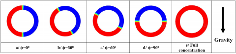
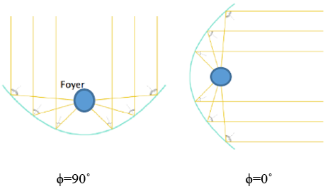
Figure 1 shows how the heat flux distribution on the outer wall of the tube changes depending on the solar tracking system and the solar elevation angle. There are four cases (ϕ=0˚, ϕ=30˚, ϕ=60˚, ϕ=90˚) are investigated in our study. The red part of the tube represents the area of the absorber, which is in the concentration range of the cylindrical parabolic mirror (see also Figure 2). The case e represents the full concentration of heat flux (Total UHF).
The boundary conditions treated are: mass flow rate; heat flux; Tinlet. We change one of these conditions and make the rest of the values constant to limit the effect of Re, Gr and Ri number, respectively.
Figure 1. Representation of different distribution of heat flux
Figure 2. Schematic representation of PTC with two cases of solar elevation angle ϕ=90˚ and ϕ=0˚
In this work, steady state simulations are run. The commercial computational fluid dynamics (CFD) solver ANSYS FLUENT 14, which is based on the finite-volume method, is used to conduct all of the numerical simulations. The first and second upwind schemes, respectively, discretize the convective terms in momentum and energy equations. The pressure is discretized by using the standard scheme. The pressure-velocity coupling is dealt with the SIMPLE algorithm.
The non-dimensional parameter of the axial velocity W which represents the uniformity of the dynamic behaviour [25]. And also, W+ which represents the axial flow velocity w, compared to the center axial velocity wc “velocity in the central axis” [5], and velocity of secondary flow Vs are defined as follows:
$W=\frac{w}{w \text { inlet }} ; W^{+}=\frac{w}{w_c}$ (4)
$V s=\sqrt{u^2+v^2}$ (5)
The non-dimensional number of the temperature ϴ which illustrates the uniformity of the thermal behaviour; and also, the conductive effect compared to the convective effect is defined as:
$\theta=\frac{\lambda(\mathrm{T}-\mathrm{Tf})}{\mathrm{qD}}$ (6)
Also, we define the dimensionless number of the temperature gradient T+ from the work of Mori et al. [5].
$T^{+}=\frac{T_{\text {wall }}-T}{T_{\text {wall }}-T_c}$ (7)
The non-dimensional Cartesian coordinates (X+, Y+) are defined as:
$X^{+}=\frac{x}{\mathrm{r}}, Y^{+}=\frac{y}{\mathrm{r}}$ (8)
where, q is the average heat flux, r is the radius of tube, winlet is the inlet velocity, wc streamwise velocity on the axis, Tfluid is the mass-averaged temperature on the selected cross-section and h is the convection heat transfer coefficient: h=q/(Twall-Tfluid).
Grashof number Gr, and Richardson number Ri, Reynolds number Re, average friction factor f, average Nusselt number Nu are defined as:
$\mathrm{Gr}=\frac{\mathrm{g} \beta \mathrm{D}^4 \mathrm{q}}{\lambda v^2}$ (9)
$R e=\frac{w_{\text {inlet }} D}{v} ; R i=\frac{\mathrm{Gr}}{R e^2}$ (10)
$N u=\frac{\mathrm{h} \mathrm{D}}{\lambda} ; f=\frac{\Delta \mathrm{P} \mathrm{D}}{\left(0.5 \rho w_{\text {inlet }}^2 \mathrm{~L}\right)}$ (11)
Prandtl number Pr can be expressed as:
$\operatorname{Pr}=\frac{v \rho c_p}{\lambda}$ (12)
Table 1. Grid independence checking “Nusselt number”
|
Grid number |
Nu moyen |
Error |
Error (%) |
|
200000 |
11.65587321 |
0.01566319 |
0.1345610601 |
|
400000 |
11.64378955 |
0.00357952 |
0.030751421 |
|
700000 |
11.64060025 |
0.00039023 |
0.003352431 |
|
800000 |
11.64021002 |
baseline |
baseline |
Figure 3. Grid in cross section
The receiver tube was modelled and meshed in three dimensions using Gambit modelling and meshing software. The grids in cross section are shown in Figure 3. Because the velocity and temperature gradients are greater near the inner wall than in any other areas in cross section, we can see that the meshing is severe in the radial direction close to the wall. The averaged Nusselt number at Re=2200 and heat flux “full concentration condition” =110.9358w/m2 from these grid systems are listed in Table 1. The grid system with 200000 cells is chosen to strike a compromise between the computational load and the numerical accuracy since it has relative deviations of averaged Nusselt at 200000 cells of 0.134%.
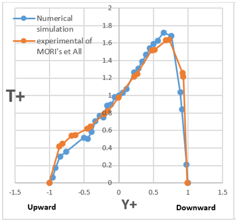
Figure 4. Comparison between the results of the numerical simulation of T+ and the experimental of Mori's et al. [4]
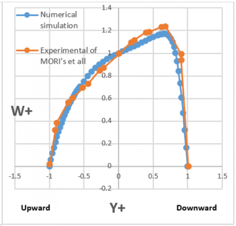
By using the dimensionless parameters T+ and W+, the results of our work were compared with the experimental results of Mori et al. [4] to validate the simulation model thermally and dynamically.
The comparison is carried out at a Reynolds number Re=4250 and a temperature gradient τ=dT/dz=11.3 degC/m in the fully developed zone of the tube, which is subjected to a constant heat flux over the entire circumference of the tube.
Figures 4 and 5 show the development of T+ and W+ along the vertical diametral plane of the tube cross-section. Knowing that the origins of the x and y axes will be the center of the cross section of the tube; and in the y axis, the down direction will be positive. It can be seen that our numerical results and the experimental results of Morri and al are in good agreement and the difference between the two curves is acceptable.
Figure 5. Comparison between the results of the numerical simulation of W+ and the experimental of Mori's et al. [4]
9.1 Thermal behaviour according to the axial direction
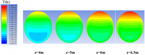
Figure 6 shows the development of temperature with the z axis at Re=2200 and heat flux q= 189.6353 w/m2 “full concentration of heat flux at the wall”. We note that the temperature field stabilizes at a position far enough from the tube inlet. The fully developed region is at z=6m and z=6.5m.
Figure 6. The temperature distribution for each cross section along the absorber
Table 2. Nu vs z
|
Z |
Nu |
|
0.5 |
9.6078205 |
|
1 |
9.72069988 |
|
2 |
9.44899764 |
|
3 |
9.21916529 |
|
4 |
9.15434401 |
|
4.5 |
9.14287882 |
|
5 |
9.13553852 |
|
6 |
9.12786342 |
|
6.5 |
9.14311098 |
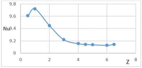
Figure 7. Nu distribution with z axis
Table 2 and Figure 7 show the distribution of Nu with z axis. The Nu number established at the fully developed region. For the mixed convection, the fully developed Nu is much higher than for the theoretical Nu of the forced laminar convection in circular tube under UHF Nu0 = 4,36.
The velocity and temperature distributions were simulated at z = 6.5 m where the axial temperature gradient was kept completely constant “fully developed region”.
9.2 Comparison between forced convection and mixed convection
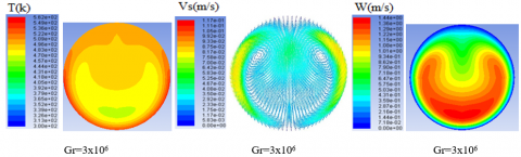
Figure 8 and Figure 9 showed the difference between mixed convection and pure forced convection. For mixed convection at Gr=3x10⁶ and Re=2200; the effect of buoyancy is clear and it forms a pair of transverse hydrodynamic secondary flow rolls which are symmetrical in the vertical diametric plane and are opposite in direction of rotation. These two vortices caused a drastic change in the velocity and temperature profile.
In Figure 8 The absorber is subjected to a heat flux over the entire circumference of the tube, which causes "under the effect of gravity" and by the mechanism of natural convection, a transport of mass and heat in the cross section in which fluid motion is generated by density differences in the fluid due to temperature gradients. Therefore, the mass is concentrated downwards and pulls the velocity profile lower, which distorts the Poiseuille profile. In addition, the layers of higher temperatures rise higher.
In Figure 9, the heat flux is concentrated on the wall of the lower half cylinder of the tube. We note that the temperature and the axial velocity fields have a bilateral concave shape in the down region of the cross section.
A/ Case one: Total uniform heat flux UHF
Figure 8. Velocity and temperature distributions at Re = 2200. Left: temperature; middle: secondary flow; right: streamwise velocity
B/ Case two: half down UHF
Figure 9. Velocity and temperature distributions at Re = 2200. Left: temperature; middle: secondary flow; right: streamwise velocity
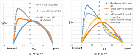
Figure 10. Non-dimensional axial velocity and gradient temperature distributions along vertical diameter at Re=2200 and Gr=3x10⁶
By comparing Figure 8 and 9 we notice the rise of two counter-rotating transverse rollers of a hydrodynamic secondary flow towards the upper half of the cross-section as the heat flux is concentrated towards the wall of the lower half of the tube.
Figure 10(a) shows the adimensional axial velocity distribution W+ in the vertical diametral plane. Knowing that the origins of the x- and y-axes will be the centre of the tube cross-section; and on the y-axis, the upward direction will be positive in all the rest of this study.
From the diagram we notice that the maximum velocity W+max increases and shifts downwards compared to the Poiseuille flow. Due to the increase in the concentration of the heat flux down the tube, W+max is larger and more considerable for the UHF half down case than for the full UHF case, but its position on the diametrical plane is the “same”.
We also notice in Figure 10(b) that the maximum value of the adimensional temperature gradient T+max increases and shifts downwards compared to the case of pure forced convection.
*Nusselt numbers and friction factors “Total uniform heat flux case”
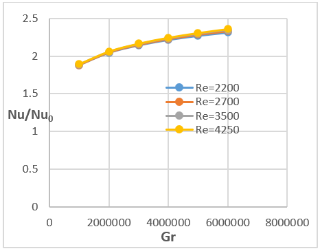
Figure 11 Shows the ratio of Nu/Nu0 in the fully developed region, relative to Gr under UHF at different Re numbers, where Nu0 is the Nusselt number for the case of purely forced convection without secondary flow. We notice that, Under the influence of thermogravitational forces, Nu becomes considerably larger than Nu0 and it reaches values more than twice its value without buoyancy force under UHF, and the effect of Re is neglected.
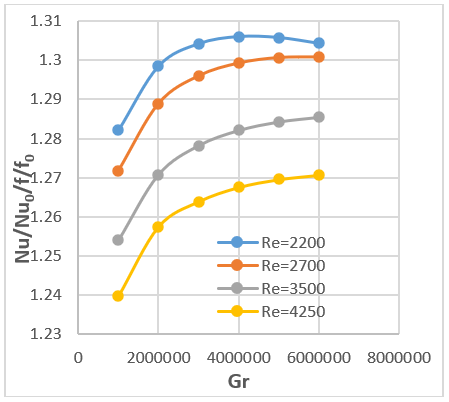
Figure 12 Presents the performance of heat transfer by mixed convection compared to that by forced convection, for different Gr and Re numbers. Knowing that the ratio f/f0 represents the friction at mixed convection f compared to that of purely forced convection f0 and it is an energetically negative term. We note that (Nu/Nu0)/(f/f0) is greater than 1 and increases with the decrease of Re number. We can say that natural convection is a positive phenomenon in terms of energy and increases the performance of the absorber.
Figure 11. Nu/Nu0 vs Gr
9.3 Comparison mixed convection for different Gr number for the case of half down UHF
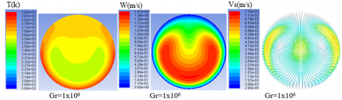
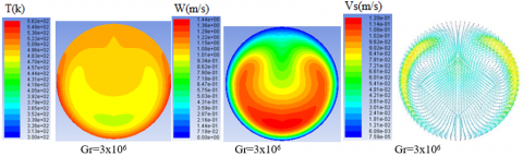
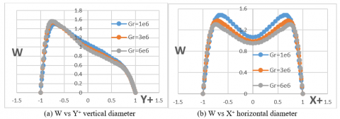
In Figure 13, the velocity and temperature distributions at Re=2200 with a half concentration UHF (ϕ=90˚) and varying Gr are depicted. It can be seen that the intensity of the secondary flow is high near the upper half cylinder of the absorber wall, and increases in its scale as the Gr number increases. With the increase of the gravitational thermal effect by the increase of the heat flux the two tourbillons are deformed and rise gradually towards the top of the tube.
By using the dimensionless parameters of velocity W and temperature T, the dynamic and thermal behaviour can be presented qualitatively in Figures 14 and 15. In the horizontal diameter, the temperature distribution in the central area of the diameter plane becomes more uniform and less concave as Gr increases.
In Figure 15(b) for the horizontal diameter, the concavity of the velocity profile becomes more open and less intense with increasing Gr.
Figure 12. (Nu/Nu0)/(f/f0) vs Gr
Figure 13. Velocity and temperature distributions at Re = 2200. Left: temperature; middle: streamwise velocity; right: secondary flow
Figure 14. ϴ for different Gr number
Figure 15. W for different Gr number
9.4 Comparison mixed convection for different Ri number “T inlet” for the case of half down UHF
Now the mass flow rate and the heat flux are fixed “m=1.1x10⁻³kg/s, q= 665.615 W/m2” and heated air is injected for the simulation at different inlet temperatures. When Tinlet increases the Richardson number decreases and the effect of natural convection becomes less significant.
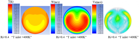
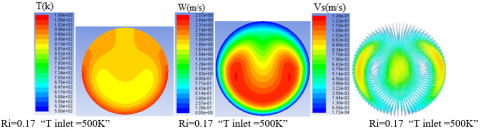
The velocity and temperature distributions under UHF (ϕ=90˚) with varied Ri are shown in Figure 16. As Ri increases from 0.0477 to 0.4 the velocity and temperature profile become more concave. It is observed that the vortex center moves progressively upwards and slightly towards the tube wall as Ri increases.
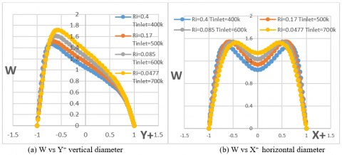
Figure 17 and Figure 18 presents the distributions of non-dimensional velocity W and temperature ϴ along horizontal and vertical diameters under half down UHF (ϕ=90˚) with varied Ri number.
In vertical diameter it is seen that the temperature distribution becomes more uniform with the increasing of Ri number (Figure 17(a)) Along the horizontal diameter (Figure 17(b)) it is noticed that the temperature gradient curve is more concave and closer to zero "at the central part of the plane" with the increase of the effect of natural convection.
For flow distributions along the vertical diameter, as Ri increases, the location of the maximum axial velocity moves downward and its value decreased (Figure 18(a)).
In Figure 18(b), with the horizontal diameter we notice that the axial velocity in the center decreased and the curve of axial velocity becomes more concave when Ri number increase.
Figure 16. Velocity and temperature distributions for different case of Ri number. Left: temperature; middle: streamwise velocity; right: secondary flow
Figure 17. ϴ for different Ri number “T inlet”
Figure 18. W for different Ri number “T inlet”
9.4 The effect of solar elevation angle
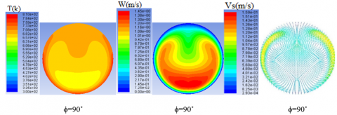
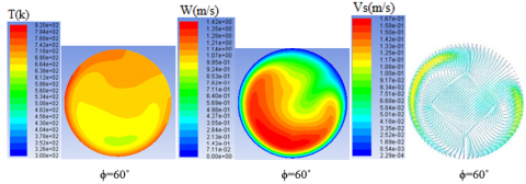
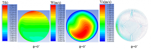
Figure 19 shows the velocity and temperature distributions at Re = 2200 and Gr = 6x10⁶ under UHF with varied solar elevation angle. With the movement of the heating around the circumference of the wall of the absorber, from the angle of solar elevation ϕ=90˚ to ϕ=60˚ and ϕ=30˚ one of the vortices rises, deforms and lengthens and the other descends downwards clockwise and the symmetry gradually disappeared.
For the case of ϕ=0˚, we notice only one vortex located in the left-lower quadrant of the cross-section.
Figure 19. Velocity and temperature distributions at Re = 2200 and Gr = 6x10⁶ under different UHF distributions cases; right: secondary flow; middle: streamwise velocity; Left: temperature
Concerning the axial speed, we note that the bilateral concave dynamic behaviour at ϕ=0˚ deforms and moves towards the heated zone from ϕ=90˚ to ϕ=0˚.
For the case of ϕ=90˚, the thermal behaviour belongs as the most homogeneous. This homogeneity is minimized and gradually degrades until the case of ϕ=0˚ where the profile of T belongs stratifies under isothermal layers oriented slightly towards the heated part "on the left".
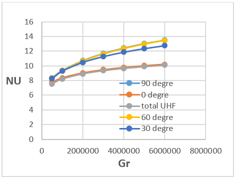
9.5 Comparison of fully developed Nu for different cases of Distribution of heat flux “solar elevation angle” about the absorber
The variation of fully developed Nusselt number with Gr are shown in Figure 20 at different solar elevation angles and Re=2200. The distribution and location of heat flux has a great effect on Nu at the same Gr and Re. For a fixed Gr, the Nu number of mixed convection under total UHF and half lateral UHF (ϕ = 0˚) is less than that under UHF (ϕ = 30˚), and this latter is lower than that under UHF (ϕ=60˚ and 90˚). The effect of natural convection is most effective for convective heat exchange when the thermal flux concentrates below the absorber and diffuses from bottom to top with the direction of Archimedes' thrust.
Figure 20. Fully developed Nu vs Gr at different solar elevation angles Re=2200
9.6 The effect of wall thickness and material
From Figure 21 we notice that the convective exchange is higher and the Nu develops rapidly for the absorber which has the most conductive wall (λ copper = 387.6 w /mk; λ steel = 16.27 w / mk) and which has a lower thickness.
Figure 21. Nu vs Gr for different wall thickness/material
This numerical study is oriented to make a thermal and dynamic analysis of the effect of natural convection on the laminar flow of air heated uniformly on the circumference of a solar absorber of a PTC. The influences of Reynolds number, Grashof number, Distribution of heat flux “solar elevation angle” and Richardson number on the fluid flow and heat transfer have been analysed. It is concluded that:
The velocity distributions of laminar flow with a significant value of Gr are significantly different from the velocity distributions of Poiseuille flow. The streamwise flow shifts downward due to buoyancy force, forming a high-speed zone at the bottom of the receiver tube. We note also the presence of two counter-rotating transverse rollers of a hydrodynamic secondary flow.
For the case of half down heated cylinder under UHF, the temperature and the axial velocity fields have a bilateral concave shape in the down region of the cross section.
For laminar flow; We note a considerable effect of the thermogravitational force on the development of the Nusselt number, so that the Nusselt number increase by the increase of Grashof number and reaches twice its value for the case of purely forced convection.
The Grashof number Gr and Richardson number Ri has an important effect in velocity field, temperature distribution and secondary flow.
Concerning the effect of the solar elevation angle; the thermal and dynamic behavior is oriented towards the heated half-cylinder of the tube. Also the thermal and dynamic symmetry break progressively when the solar elevation angle decreases from ϕ=90° to ϕ=0°.
When the heat flux diffuses from the bottom to the top of the absorber with the axis and direction of Archimedes' thrust, natural convection is most effective for convective exchange “the case ϕ= 90°” and Nusselt number reaches more than three times its value in the case of pure forced convection.
Finally, it should be noted that the knowledge of the thermal and dynamic behaviour of a fluid such as air subjected to mixed laminar convection in a solar absorber of PTC is very important for a good design of the latter.
|
Cp |
Specific heat capacity, J. kg-1. K-1 |
|
D |
Hydraulic diameter, m |
|
f |
Friction factor |
|
g |
Gravitational acceleration, m/s2 |
|
Gr |
Grashof number |
|
h |
Convection heat transfer coefficient, W/(m2.K) |
|
L |
Length of receiver tube, m |
|
m |
Mass flow rate, kg/s |
|
Nu |
Nusselt number “mixed convection” |
|
Nu0 |
Nusselt number “forced convection” |
|
P |
Static pressure, Pa |
|
Pr |
Prandtl number |
|
q |
Heat flux, W/m2 |
|
Q |
Heat transfer rate, W |
|
r |
Radius, m |
|
Re |
Reynolds number |
|
Ri |
Richardson number |
|
T |
Temperature, K |
|
Tc, wc |
Temperature and velocity in center axis |
|
T+ |
Dimensionless temperature |
|
Vs |
Velocity magnitude of secondary flow, m/s |
|
u, v, w |
x, y, z velocity component, m/s |
|
W, W+ |
Non-dimensionnel axial velocity |
|
x, y, z |
Cartesian coordinates, m |
|
X+ , Y+ |
Non-dimensional Cartesian coordinates |
|
Greek symbols |
|
|
$\beta$ |
volumetric expansion coefficient, 1/K |
|
$\phi$ |
solar elevation angle, ֯ |
|
Ɵ |
dimensionless temperature |
|
λ |
thermal conductivity, W/(m.K) |
|
µ |
dynamic viscosity, kg. m-1.s-1 |
|
υ |
kinematic viscosity, m2/s |
|
ρ |
density, kg/m3 |
|
τ |
the temperature gradient along the tube axis, K/m |
[1] Roldan, M.I., Valenzuela, L., Zarza, E. (2013). Thermal analysis of solar receiver pipes with superheated steam. Applied Energy, 103: 73e84. https://doi.org/10.1016/j.apenergy.2012.10.021
[2] Song, X.W., Dong, G.B., Gao, F.Y., Diao, X.G., Zheng, L.Q., Zhou, F.Y. (2014). A numerical study of parabolic trough receiver with nonuniform heat flux and helical screw-tape inserts. Energy, 77: 771e82. https://doi.org/10.1016/j.energy.2014.09.049
[3] Barozzi, G.S., Zanchini, E., Mariotti, M. (1985). Experimental investigation of combined forced and free convection in horizontal and inclined tubes. Meccanica, 20: 18-27. https://doi.org/10.1007/BF02337057
[4] Mori, Y., Futagami, K., Tokuda, S., Nakamura, M. (1966). Forced convective heat transfer in uniformly heated horizontal tubes 1st report-experimental study on the effect of buoyancy. International Journal of Heat and Mass Transfer, 9(5): 453-463. https://doi.org/10.1016/0017-9310(66)90101-3
[5] Bergles, A.E., Simonds, R.R. (1971). Combined forced and free convection for laminar flow in horizontal tubes with uniform heat flux. International Journal of Heat and Mass Transfer, 14(12): 1989-2000. https://doi.org/10.1016/0017-9310(71)90023-8
[6] Mori, Y., Futagami, K. (1967). Forced convective heat transfer in uniformly heated horizontal tubes 2nd report-theoretical study. International Journal of Heat and Mass Transfer, 10(12): 1801-1813. https://doi.org/10.1016/0017-9310(67)90051-8
[7] Lei, Q.M., Trupp, A.C. (1991). Experimental study of laminar mixed convection in the entrance region of a horizontal semicircular duct. International Journal of Heat and Mass Transfer, 34(9): 2361-2372. https://doi.org/10.1016/0017-9310(91)90061-I
[8] Shome, B., Jensen, M.K. (1995). Mixd convection laminar flow and heat transfer of liquids in isothermal horizontal circular ducts. International Journal of Heat and Mass Transfer, 38(11): 1945-1956. https://doi.org/10.1016/0017-9310(94)00328-S
[9] Cheng, Z.D., He, Y.L., Cui, F.Q. (2012). Numerical study of heat transfer enhancement by unilateral longitudinal vortex generators inside parabolic trough solar receivers. International Journal of Heat and Mass Transfer, 55(21-22): 5631-5641. https://doi.org/10.1016/j.ijheatmasstransfer.2012.05.057
[10] Huang, Z., Li, Z.Y., Tao, W.Q. (2015). Numerical study on combined natural and forced convection in the fully-developed turbulent region for a horizontal circular tube heated by non-uniform heat flux. Applied Energy, 185: 2194-2080. https://doi.org/10.1016/j.apenergy.2015.11.066
[11] Li, Z.Y., Huang, Z., Tao, W.Q. (2016). Three-dimensional numerical study on fully-developed mixed laminar convection in parabolic trough solar receiver tube. Energy, 113: 1288-1303. https://doi.org/10.1016/j.energy.2016.07.148
[12] Huang, Z., Li, Z.Y., Yu, G.L., Tao, W.Q. (2016). Numerical investigations on fully-developed mixed turbulent convection in dimpled parabolic trough receiver tubes. Applied Thermal Engineering, 114: 1287-1299. https://doi.org/10.1016/j.applthermaleng.2016.10.012
[13] Lu, J.F., Ding, J., Yang, J.P., Yang, X.X. (2013). Nonuniform heat transfer model and performance of parabolic trough solar receiver. Energy, 59: 666-675. https://doi.org/10.1016/j.energy.2013.07.052
[14] Muñoz, J., Abánades, A. (2011). Analysis of internal helically finned tubes for parabolic trough design by CFD tool. Applied Energy, 88(11): 4139-4149. https://doi.org/10.1016/j.apenergy.2011.04.026
[15] Hachicha, A.A., Rodríguez, I., Capdevila, R., Oliva, A. (2013). Heat transfer analysis and numerical simulation of a parabolic trough solar collector. Applied Energy, 111: 581-592. https://doi.org/10.1016/j.apenergy.2013.04.067
[16] Polyakov, A.F. (1974). Development of secondary free-convection currents in forced turbulent flow in horizontal tubes. Journal of Applied Mechanics and Technical Physics, 15(5): 632-637. https://doi.org/10.1007/BF00851521
[17] Petukhov, B.S., Polyakov, A.F., Launder, B.E. (1988). Heat Transfer in Turbulent Mixed Convection. New York: Hemisphere Publishing Corporation. https://doi.org/10.1137/1032068
[18] Abdelmeguid, A.M., Spalding, D.B. (1979). Turbulent flow and heat transfer in pipes with buoyancy effects. Journal of Fluid Mechanics, 94(2): 383-400. https://doi.org/10.1017/S0022112079001087
[19] Grassi, W., Testi, D. (2006). Heat transfer correlations for turbulent mixed convection in the entrance region of a uniformly heated horizontal tube. Journal of Heat Transfer, 128(10): 1103-1107. https://doi.org/10.1115/1.2345436
[20] Forooghi, P., Hooman, K. (2013). Numerical study of turbulent convection in inclined pipes with significant buoyancy influence. International Journal of Heat and Mass Transfer, 61: 310-322. https://doi.org/10.1016/j.ijheatmasstransfer.2013.02.014
[21] Faheem, A., Ranzi, G., Fiorito, F., Lei, C.W. (2016). A numerical study of turbulent mixed convection in a smooth horizontal pipe. Journal of Heat Transfer, 138(1): 012501. https://doi.org/10.1115/1.4031112
[22] Mohamed, H.A., Salman, Y.K. (2007). Experimental investigation of mixed convection heat transfer for thermally developing flow in a horizontal circular cylinder. Applied Thermal Enginnering, 27(8-9): 1522-1533. https://doi.org/10.1016/j.applthermaleng.2006.09.023
[23] Choi, D.K., Choi, D.H. (1994). Developing mixed convection flow in a horizontal tube under circumferentially non-uniform heating. International Journal of Heat and Mass Transfer, 37(13): 1899-1913. https://doi.org/10.1016/0017-9310(94)90330-1
[24] Wirz, M., Roesle, M., Steinfeld, A. (2012). Three-dimensional optical and thermal numerical model of solar tubular receivers in parabolic trough concentrators. Journal of Solar Energy Engineering, 134(4): 041012. https://doi.org/10.1115/1.4007494
[25] Choudhury, D., Patankar, S.V. (1988). Combined forced and free laminar convection in the entrance region of an inclined isothermal tube. Journal of Heat Transfer, 110(4a): 901-909. https://doi.org/10.1115/1.3250591