Yuxin Li | Fenjun Liu | Hongli Jing | Tong Zhang* | Zengsheng Li
© 2022 IIETA. This article is published by IIETA and is licensed under the CC BY 4.0 license (http://creativecommons.org/licenses/by/4.0/).
OPEN ACCESS
The magnesium-based hydrogen storage alloy has a very good prospect to be applied in the market of lightweight automobile due to its merits of light weight, excellent discharge performance, long cycle life, and large hydrogen storage capacity. However, existing studies on magnesium-based hydrogen storage alloy have a series of shortcomings such as the insufficient works in terms of model reasonability analysis, heat transfer behavior analysis, heat control scheme design, and comparative experiment analysis, etc. In view of these problems, this paper studied the thermal effect and heat control strategy of the Mg-based Hydrogen Storage Alloy (MHSA) system for lightweight automobile. At first, this paper constructed numerical models for the fluid-solid coupled heat exchange region and the heat conduction region in the system; then, based on the law of energy conservation, a heat transfer behavior model of the MHSA system was established and used to analyze the thermal effect of the system. After that, according to the driving process of hydrogen fuel cell electric vehicle, the working process of the MHSA system was further analyzed to study the heat control process. Next, this paper proposed a new idea for the heat control of the MHSA system, gave a few tips for the simulations, and presented the flow of the heat control scheme of the system. At last, the experimental results were given and analyzed.
Mg-based hydrogen storage alloy, lightweight automobile, thermal effect, heat control
Hydrogen fuel is a kind of green, renewable, clean energy source that can provide powerful output for automobiles, and it has a very huge development potential [1-7]. Hydrogen storage is the largest constraint on hydrogen engines and hydrogen fuel cells used in electric vehicles and hybrid electric vehicles [8-13]. Compared with zirconium-based, titanium-based, and rare earth elements-based hydrogen storage alloys, the magnesium-based hydrogen storage alloy has a few merits including light weight, excellent discharge performance, long cycle life, and large hydrogen storage capacity, thus it has a very good prospect to be applied in the market of lightweight automobile.
During the hydrogen adsorption and desorption process, the Mg-based hydrogen storage alloy is subjected to the control of the heat transfer process. To make sure that the hydrogen supply could meet the driving requirement of automobile, it’s a necessary work to master the real-time temperature distribution of the Mg-based hydrogen storage alloy material. When a vehicle is running, its power and load are changing constantly, and the thermodynamic parameters of the Mg-based hydrogen storage alloy would change with them accordingly [14-18]. In order to accurately attain the heat demand of the system, the changes of the temperature field need to be predicted in real time so that the heat control of the hydrogen supply process could be performed accurately.
Xu and Xiao [19] designed an experiment to use the hydrogen storage performance tester and the Netzch STA 449F3 thermo-analyzer to study the impact of TiMn2, TiAl, and Ti on the hydrogen storage properties of the Mg2FeH6 system. The results of temperature programmed desorption test and isothermal hydrogen desorption test showed that, the hydrogen storage desorption kinetics of TiMn2/TiAl/Ti-doped Mg2FeH6 and unalloyed Mg2FeH6 are quite similar, and the reaction rate of the former is slightly higher. These catalysts can decrease the endothermic peak temperature by about 27°C, among them, the TiMn2 exhibited the best catalytic performance, followed by pure Ti, and the TiAl was the worst. Ouyang et al. [20] proposed that a key issue in the application of fuel cells is the research progress of high-capacity hydrogen storage alloys, among the many candidate alloys for storing hydrogen, the authors chose the Mg-based alloy based on its merits of high abundance, low density, and large hydrogen storage capacity. However, the actual use of Mg-based hydrogen storage alloy is still limited by its slow kinetics and relatively stable thermodynamic features. This paper summarized the advanced synthetic methods and effective strategies for enhancing the performance of Mg-based hydrogen storage alloy, including alloying, nano-structuring, doping with additives, and forming nano-composites with other hydrides. At last, the authors briefly discussed the prospect of further enhancing the performance of the Mg-based hydrogen storage alloy material. Zhou et al. [21] took crystallized carbon prepared from anthracite coal as milling agent to prepare Mg-based hydrogen storage material through reactive milling of magnesium under hydrogen atmosphere. The results of XRD analysis showed that, in the presence of 30 wt.% crystallized carbon, after being grinded for 3h under 1 MPa H2, the Mg was easily hydrogenated and turned into β-MgH2 with a crystal grain size of 29.7 nm and a small amount of γ-MgH2. The enthalpy and entropy changes of the hydrogen desorption reaction were 42.7 kJ/mol and 80.7 J/mol K, respectively, and these values were attained from the calculation of the vant-Hoff equation based on the p-C-T data at 300-380°C.
Field scholars in the world have conducted various studies on the optimization and design of the structure of the Mg-based hydrogen storage alloy material, but after reviewing the relevant literatures carefully, it’s found that the existing works generally lack model reasonability analysis, heat transfer behavior analysis, heat control scheme design, and comparative experiment analysis. Therefore, regarding these issues, this paper aims to study the thermal effect and heat control strategy of MHSA system for lightweight automobile. In the second chapter, this paper constructed numerical models for the fluid-solid coupled heat exchange region and the heat conduction region in the system; then, based on the law of energy conservation, a heat transfer behavior model of the MHSA system was established and used to analyze the thermal effect of the system. In the third chapter, according to the driving process of hydrogen fuel cell electric vehicle, this paper analyzed the working process of the MHSA system to further study the heat control process. In the fourth chapter, this paper proposed a new idea for the heat control of the MHSA system, gave a few tips for the simulations, and presented the flow of the heat control scheme of the system. In the fifth chapter, the experimental results were given and analyzed.
In recent years, the Mg-based hydrogen storage alloy has attracted more attention from field scholars due to its many merits of light weight, high hydrogen storage capacity, low price, green, and pollution-free. Table 1 gives the properties of the Mg-based hydrogen storage alloy, as can be seen from the table, the mass percent of hydrogen storage of the alloy is low, the hydrides are stable, and oxide films are easily formed on the surface.
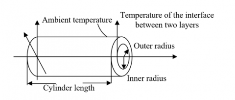
To analyze the thermal effect of the MHSA system, at first, this paper respectively constructed models for the fluid-solid coupled heat exchange region and the heat conduction region in the system. Figure 1 shows the structure of the hydrogen storage tank. The process of hydrogen storage reaction is accompanied by the desorption of energy, in this paper, the initial temperature of the heat exchange part is set to 300K. From inside to outside, the heat exchange part contains a heating sleeve, the inner and outer cooling sleeves, the inner and outer cooling pipes, and a heating rod.
Table 1. Properties of Mg-based hydrogen storage alloy
|
Type of the hydrogen storage product |
Hy-STOR301 |
|
|
Nitrogen adsorption reaction |
Mg2Ni+3H2=MgH2+MgNiH4 |
|
|
Density |
Kg/m3 |
3200 |
|
Mass percent of hydrogen storage |
MgH2 |
7.1 |
|
MgNiH4 |
3.5 |
|
|
Mg2Ni |
5.7 |
|
|
Reaction heat |
kJ/mol.H2 |
63.8 |
|
Hydrogen adsorption temperature |
℃ |
26 |
|
Hydrogen desorption temperature |
℃ |
261 |
|
Hydrogen adsorption pressure |
bar |
0.004 |
|
Hydrogen desorption pressure |
bar |
2 |
|
Daily leakage rate |
% |
2 |
Figure 1. Structure of the hydrogen storage tank
Assuming: Sg represents the cross-sectional area of the cooling pipe; Cg represents the perimeter of the cross-section; eg represents the diameter of the cross-section, then, the feature size of the cooling medium channel in the cooling pipe group of the fluid-solid coupled region could be calculated based on the formula below:
$e_g=\frac{4 S_g}{C_g}$ (1)
Assuming: SNo represents the Reynolds coefficient of the smooth pipeline; φ represents the density of the cooling medium; κ represents the flow rate of the fluid; δ represents the viscosity coefficient of the cooling medium, then the flow form of the medium can be judged based on the following formula:
$S N_0=\frac{\phi \kappa e_g}{\delta}$ (2)
When SNo is less than 2300, the flow form is judged to be laminar flow; when SNo is greater than 4000, the flow form is judged to be turbulent flow; other cases are judged to be the transitional stage. In order to determine the convective heat transfer coefficient, the Nussel number needs to be calculated. The calculation formulas for laminar flow and turbulent flow are:
$M_v=1.86 \cdot\left(\frac{S N_o T_s}{K / e_g}\right)^{1 / 3} \cdot\left(\frac{\delta_g}{\delta_q}\right)^{0.14}$ (3)
$M_v=0.027 \cdot S N_o^{4 / 5} \cdot T_s^{3 / 10}$ (4)
The convective heat transfer coefficient of the fluid-solid coupled interface can be calculated by the following formula:
$f_q=M_v \cdot \frac{\mu_g}{e_g}$ (5)
From inside to the outside, the heat exchanges between the heating rod, the inner cooling sleeve, the inner and outer hydrogen storage layers, and the outer cooling sleeve belong to the heat conduction process. Assuming: Wμ represents the heat flux; μ represents the thermal conductivity coefficient; Ψ represents the temperature; S represents the area; ∂Ψ/∂m represents the temperature gradient, based on the Fourier’s Law, the expression of the mathematical model of the heat conduction region is:
$W_\mu=-\mu S \frac{\partial \Psi}{\partial m}$ (6)
The law of energy conservation is the basis for analyzing the distribution of temperature field in the MHSA system, thus the law is applied to the microelements in the system, the sum of the work done by the volume force and surface force of the microelement and the net heat flux flowing into the microelement is equal to the increase of its internal thermodynamic energy. Assuming: f represents the specific enthalpy; ε represents the density; ϑ represents the time; t represents the pressure; Ṽ represents the velocity vector of the microelement and it satisfies Ṽ=(v, u, q); μ represents the thermal conductivity coefficient; P represents the temperature; ϕ represents the heat energy produced by viscosity; Rf represents the inner heat source of the microelement; $t \operatorname{div} \tilde{V}$ represents the work done by the surface force on the microelement, then there is:
$\frac{\partial(\varepsilon f)}{\partial \vartheta}+\frac{\partial(\varepsilon v f)}{\partial a}+\frac{\varepsilon(u f)}{\partial b}+\frac{\varepsilon(q f)}{\partial c}$$=-t \operatorname{div} \tilde{V}+\operatorname{div}(\mu g$ radP $)+\varphi+R_f$ (7)
Because the Mg-based hydrogen storage alloy material is solid, there are Ṽ=0, ϕ=0, and f=dtP; assuming h represents the volume heat source, then there is:
$\varepsilon d_t \frac{\partial P}{\partial \tau}=\mu\left(\frac{\partial^2 P}{\partial a^2}+\frac{\partial^2 P}{\partial b^2}+\frac{\partial^2 P}{\partial c^2}\right)+\dot{h}$ (8)
For electric vehicles and hybrid electric vehicles, the required driving power is directly related to the state of hydrogen supply, therefore, to meet the driving requirements of automobiles, it’s necessary to accurately control the hydrogen supply state of the MHSA system.
Since reaching the temperature of the hydrogen desorption platform, and a hydrogen-desorption pressure greater than ambient pressure, are the two necessary conditions for the hydrogen desorption of the Mg-based hydrogen storage alloy, the heat control design of the MHSA system is the basis for ensuring the driving requirement of the automobile, and the purpose is to ensure than the system could always run at a temperature suitable for hydrogen desorption.
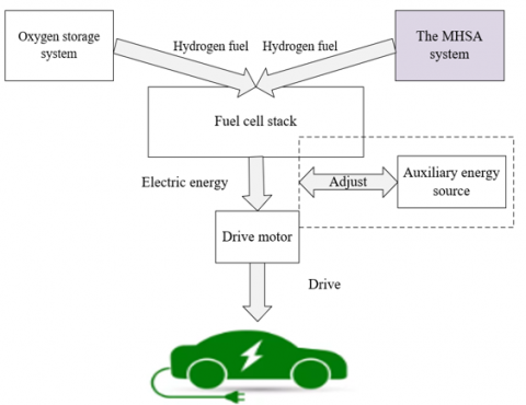
Figure 2 shows the driving process of the hydrogen fuel cell electric vehicle. The cooperation of the MHSA system, the hydrogen fuel cell electric vehicle, and the driving system of the vehicle completes the driving process of the vehicle. To better figure out the heat control process, this paper analyzed the working process of the MHSA system.
Assuming: Iout represents the output current of the fuel cell; S1 represents the area of the interface of the catalyst layer; id and ix represent the local current density of the cathode and the anode catalyst layers; Uout represents the output voltage of the fuel cell; O represents the thermodynamic electromotive force of the fuel cell; δAC,d and δAC,x represent the activation polarization overpotential of the cathode and the anode; δOL,ME and δCH,DI represent the ohmic polarization overpotential of the proton membrane and the diffusion layer, then the external features of the fuel cell can be described by the following formulas:
$I_{\text {out }}=\frac{1}{S} \iint_d^i d S_1=-\frac{1}{S} \iint_s^i d S_1$ (9)
$U_{\text {out }}=O-\left|\delta_{A C, d}\right|-\delta_{A C, x}-\delta_{O H, M E}-\delta_{O H, D I}$ (10)
The formula for calculating the output power of the fuel cell is:
$G L_{G-C E}=U_{C E} \bullet S D_{O U}$ (11)
The MHSA system continuously feeds hydrogen into the fuel cell, reactions happen at the electrodes inside the fuel cell to convert hydrogen and oxygen into liquid water. Assuming: O represents the electromotive force of the cell; O0 represents the standard reversible electromotive force; TF2 and Te1 represent the pressure of hydrogen and oxygen; Ψ represents the operating temperature of the fuel cell; G represents the Faraday constant; S represents the molar gas constant, then the relationship between TH2, To1, and O can be expressed as:
$O=O^0-0.85 \times 10^{-3}(\Psi-298.15)+\frac{S \Psi}{2 G} \ln \left(T_{F_2} \cdot T_{E_2}^{1 / 2}\right)$ (12)
Assuming: ud and ux represent the inlet flow rate of oxygen and hydrogen; aE2,in and aH2,in represent the molar ratio of oxygen and hydrogen at the inlet; T0,d and T0,x represent the cathode pressure and the anode pressure; Φd and Φx represent the chemical equivalent inlet coefficient of oxygen and hydrogen; X2 represents the cross-section of the inlet of the flow channel, then the relationship between ud, ux, and Iout can be expressed as:
$u_d=-\frac{\Phi_d}{a_{E_2, \text { in }}} \frac{I_{\text {out }}}{4 G X_2} \frac{S P_0}{T_{0, d}}$ (13)
$u_x=-\frac{\Phi_x}{a_{F_2, i n}} \frac{I_{\text {out }}}{4 G X_2} \frac{S \Psi_0}{T_{0, x}}$ (14)
According to above formulas, Iout increases linearly with the increase of ud and ux.
Figure 2. Driving process of the hydrogen fuel cell electric vehicle
To make sure that the MHSA system can output the amount of hydrogen gas that meets the power required for automobile operation, it is necessary to control the amount of additional heat of the system, namely to perform heat control on the system.
After analyzing the working process of the hydrogen fuel cell vehicle, it’s known that the working process of the MHSA system is affected by three kinds of heat power: the convective heat exchange power generated by convective heat exchange with environment ẆCO, the heat power consumed for reaching the temperature of the hydrogen desorption platform ẆN, and the heat power consumed by heat adsorption ẆF2, then the total input heating power of the system ẆHE can be expressed as:
$\dot{W}_{H E}=\dot{W}_{C O}+\dot{W}_N+\dot{W}_{F_2}$ (15)
To calculate the size of ẆHE, the calculation of ẆCO, ẆN, and ẆF2 must be completed first. The calculation of ẆCO needs to analyze the surface temperature field of the MHSA system and its distribution, and the calculation of ẆN and ẆF2 needs to judge whether the surface temperature field of the system reaches the working temperature or not. When the surface temperature is lower than the working temperature, ẆN will heat the Mg-based hydrogen storage alloy, when the surface temperature reaches the working temperature, ẆF2 will be generated accordingly and used for absorbing heat and releasing hydrogen of the Mg-based hydrogen storage alloy.
To compile the 3D simulation software for analyzing the thermal effect and stimulating the heat control process of the MHSA system, we need to figure out the influencing factors of the temperature field change during the working process of the MHSA system used for lightweight electric vehicles and analyze the relationship between these factors and the temperature field. According to the thermal effect analysis and simulation verification of the MHSA system, a few parameters including vehicle speed, ambient temperature and fuel cell output power were selected, and were mainly considered during the simulation of the heat control process. Assuming: Mv represents the Nusselt number; fAI represents the convective heat transfer coefficient of the air side; Ef represents the hydraulic radius of the cross-section of the MHSA system; lAI represents the heat conduction coefficient of the air side; SN represents the Reynolds number; U represents the vehicle speed; uAI represents the moving viscosity of the air, then there are:
$M_v=\frac{f_{A I} E_f}{l_{A I}}$$=0.3+\frac{0.62 S N^{1 / 2} \operatorname{Pr}^{1 / 3}}{\left[1+(0.4 / \operatorname{Pr})^{2 / 3}\right]^{1 / 4}}\left[1+\left(\frac{S N}{28,200}\right)^{5 / 8}\right]^{4 / 5}$ (16)
$S N_o=\frac{U E_f}{u_{A I}}$ (17)
Assuming: Pg represents the ambient air temperature; PN represents the surface temperature of the MHSA system, then there is:
$\dot{W}_{C O}=f_{A I}\left(P_g-P_N\right)$ (18)
According to above analysis, it’s known that U can affect SN, and then have an impact on fAI further. The convective heat transfer power ẆCO generated by the convective heat transfer with the environment can reflect the impact of ambient temperature on heat exchange. The impact of two factors, U and ambient temperature, on the MHSA system is the convective heat transfer loss generated between the system and the environment.
Assuming: ṅF2 represents the hydrogen supply of the MHSA system, by adjusting ṅF2, the value of ẆF2 can be determined and then the size of the output power of fuel cell could be determined further, and ẆF2 has a great impact on the temperature field of the system. Assuming: Δf represents the heat of the hydrogen desorption reaction during the working process of the Mg-based hydrogen storage alloy, namely the enthalpy change of the reaction, then the relationship between ṅF2 and ẆF2 can be expressed as follows:
$\dot{W}_{F_2}=\dot{n}_{F_2} \times \Delta f$ (19)
On the one hand, the amount of hydrogen supplied by the MHSA system can affect the heat adsorption power of the Mg-based hydrogen storage alloy ẆF2 and the total heating control power ẆHE, on the other hand, the output power of the fuel cell and the driving requirement of the automobile should be met, therefore, the driving status of the vehicle should be figured out to calculate the amount of hydrogen supplied by the MHSA system. Based on the comprehensive analysis of the working process of the hydrogen fuel cell, the MHSA system, and the driving system of the automobile, the changes in the amount of hydrogen supplied by the MHSA system during the working process could be summarized.
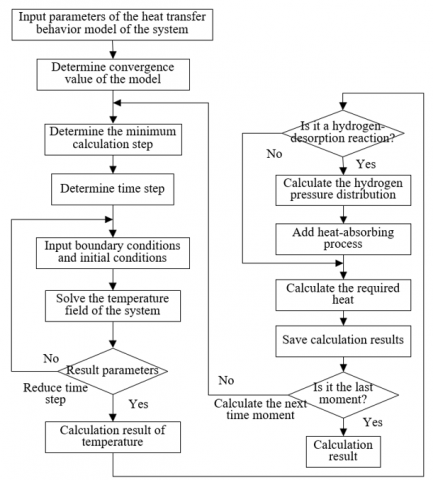
Figure 3. Flow of the heat control scheme for the MHSA system
When GLG-CE remains unchanged, the amount of hydrogen supplied by the MHSA system is constant. Assuming: ΔfG-CE represents the enthalpy of the hydrogen participating in the fuel cell reaction; M represents the number of fuel cell stacks contained in the fuel cell, then the relationship between ṅF2 and GLG-CE is given by the following formula:
$G L_{G-C E}=\dot{n}_{F_2} \bullet \Delta F_{G-C E}=\frac{M K_{O U}}{2 G} \Delta F_{G-C E}$ (20)
It can be known that, when the driving requirement of the automobile changes, GLG-CE will change in real time, and this can affect the amount of hydrogen supplied by the MHSA system ṅF2 to a certain extent.
Figure 3 shows the flow of the heat control scheme for the MHSA system. The flow is divided into four links: parameter input of the heat transfer behavior model, temperature distribution of the system temperature field, calculation of hydrogen adsorption and desorption, and save calculation results.
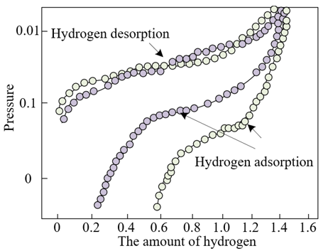
Test pieces of the Mg-based hydrogen storage alloy were prepared by two methods, the ingot casting method, and the fast quenching method, then their isothermal curves of hydrogen adsorption and desorption were tested, and the results are shown in Figure 4. The values of the hydrogen adsorption capacity of the test pieces prepared by the two methods are close, but there’re large differences between the two in terms of the hydrogen desorption platform.
Figure 4. Isothermal curves of hydrogen adsorption and desorption of the MHSA system
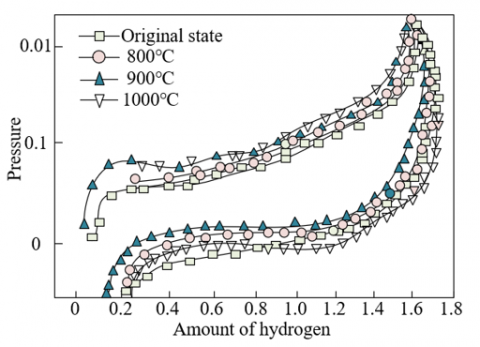
Figure 5. Isothermal curves of hydrogen adsorption and desorption of heat-treated Mg-based hydrogen storage alloy
The prepared test pieces of Mg-based hydrogen storage alloy were subjected to heat treatment in a vacuum heat treatment furnace for 3 hours at different temperatures. Figure 5 shows the isothermal curves of hydrogen adsorption and desorption of the heat-treated Mg-based hydrogen storage alloy. For the test pieces of Mg-based hydrogen storage alloy prepared by the two methods, after subjected to heat treatment at 800℃, 900℃, and 1000℃, in the isothermal balance of the hydrogen adsorption and desorption of the test pieces, the hydrogen adsorption and desorption platform grew wider to a certain extent, and the capacity of hydrogen adsorption and desorption had improved as well. By comparing the isothermal curves of hydrogen adsorption and desorption of test pieces prepared by the same method but heat-treated at different temperatures, it’s known that the heat treatment temperature for the maximum hydrogen adsorption and desorption capacity is 900℃, and the hydrogen storage performance at this time is the best.
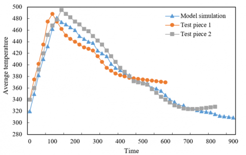
Figure 6. Temperature change verification curves of the reaction layer of the MHSA system
The temperature field of the MHSA system was tested through experiment. Referring to the mass conservation equation and the energy conservation equation, this paper built a heat transfer behavior model for the MHSA system, and the energy source term of the MHSA system was simulated and compiled by the UDF programming method in Fluent. Then, the simulation results and the experimental results of test pieces prepared by the two methods were compared. Figure 6 gives the temperature change verification curves of the reaction layer of the MHSA system. According to the figure, the temperature change law of the reaction layer of the MHSA system is basically consistent with the experimental curves of the test pieces, which had verified the effectiveness of the constructed model.
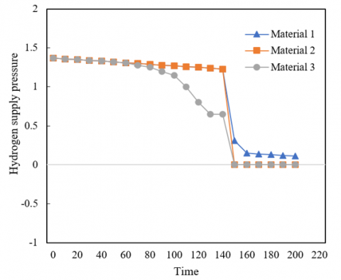
Figure 7 shows the changes in the hydrogen supply pressure of the MHSA system under different doping conditions. As can be seen from the figure, under the condition that the hydrogen pressure at the inlet of the automobile fuel cell is fixed, for the doped and un-doped alloys, there’re certain differences in the time duration for maintaining normal hydrogen supply, wherein the un-doped alloy can only supply hydrogen for about 1 minute and 50 seconds, the hydrogen supply pressure of the alloys doped with AlCl3 and Nb2O5 can supply hydrogen for about 2 minutes and 40 seconds. The pressure fluctuation of the doped alloy is smaller, and the reason is that the addition of AlCl3 and Nb2O5 has effectively lowered the apparent activation energy of the decomposition and hydrogen desorption of the alloy.
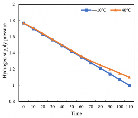
Figure 8 shows the changes in the hydrogen supply pressure of the MHSA system at different ambient temperatures. According to the figure, at the ambient temperature of -10℃ to 40℃, within 1 minute before hydrogen desorption, the hydrogen supply pressure of the system didn’t differ much. After 1 minute, the hydrogen supply pressure of the system at -10℃ was smaller than that at 40℃, and the decrement increased gradually. It can be inferred that the ambient temperature has a certain effect on the convective heat transfer of the shell, and its impact on the hydrogen supply pressure of the system is average.
Figure 7. Hydrogen supply pressure of the MHSA system under different doping conditions
Figure 8. Hydrogen supply pressure of the MHSA system at different ambient temperatures
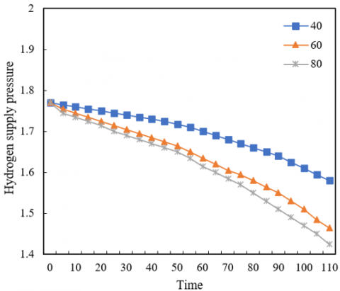
Figure 9. Hydrogen supply pressure of the MHSA system under different output power values
Figure 9 shows the changes in the hydrogen supply pressure of the MHSA system under different output power values of automobile fuel cell. According to the figure, under different driving conditions of the automobile, the output power of fuel cell has a significant impact on the hydrogen supply pressure of the MHSA system. As the hydrogen desorption process went on, the hydrogen supply pressure of the system kept dropping; at the same time, as the output power increased from 20 kW to 80 kW, the hydrogen supply pressure decreased accordingly.
This paper studied the thermal effect and control strategy of MHSA system for lightweight automobile. At first, this paper constructed numerical models for the fluid-solid coupled heat exchange region and the heat conduction region in the system; then, based on the law of energy conservation, a heat transfer behavior model of the MHSA system was established and used to analyze the thermal effect of the system. After that, according to the driving process of hydrogen fuel cell electric vehicle, the working process of the MHSA system was further analyzed to study the heat control process. Next, this paper proposed a new idea for the heat control of the MHSA system, gave a few tips for the simulations, and presented the flow of the heat control scheme of the system.
Combining with experiment, the isothermal curves of hydrogen adsorption and desorption of the MHSA system were plotted, a 3h heat treatment comparative experiment was carried out, and the experimental results showed that the heat treatment temperature for the maximum hydrogen adsorption and desorption capacity is 900℃, and the hydrogen storage performance at this time is the best. Then, the simulation results and the experimental results of test pieces prepared by two methods were compared, and the experimental results showed that the law of temperature change of the reaction layer of the MHSA system was basically consistent with the experimental curves of the test pieces, which had verified the effectiveness of the constructed model. Moreover, the changes in the hydrogen supply pressure of the MHSA system under different doping conditions, different ambient temperatures, and different output power values were given. At last, the corresponding analysis results and conclusions were drawn.
The paper was supported by the Industrial Demonstration of Magnesium Based Hydrogen Storage Materials (Grant No.: 1505-2019-86-2).
[1] Li, Z., Luo, Y. (2019). Comparisons of hazard distances and accident durations between hydrogen vehicles and CNG vehicles. International Journal of Hydrogen Energy, 44(17): 8954-8959. https://doi.org/10.1016/j.ijhydene.2018.07.074
[2] Ugurlu, A., Oztuna, S. (2020). How liquid hydrogen production methods affect emissions in liquid hydrogen powered vehicles? International Journal of Hydrogen Energy, 45(60): 35269-35280. https://doi.org/10.1016/j.ijhydene.2020.01.250
[3] Bensenouci, A., Teggar, M., Medjelled, A., Benchatti, A. (2021). Thermodynamic analysis of hydrogen production by a thermochemical cycle based on magnesium-chlorine. International Journal of Heat and Technology, 39(2): 521-530. https://doi.org/10.18280/ijht.390222
[4] Ridha, H., Al-Abboodi, N.K.F. (2022). Two-phase liquid-solid hydrodynamics of inclined fluidized beds. Power Engineering and Engineering Thermophysics, 1(1): 33-47. https://doi.org/10.56578/peet010105
[5] Liu, Z., Kendall, K., Yan, X. (2018). China progress on renewable energy vehicles: Fuel cells, hydrogen and battery hybrid vehicles. Energies, 12(1), 54. https://doi.org/10.3390/en12010054
[6] Huang, Y.S., Tian, L.X., Zhao, H.F., Sun, S.Z., Deng, J.J., Liu, S. (2021). Location and volume determination of hydrogen refueling stations based on oligopoly equilibrium. International Journal of Heat and Technology, 39(1): 101-106. https://doi.org/10.18280/ijht.390110
[7] Hosseini, S.E., Butler, B. (2020). An overview of development and challenges in hydrogen powered vehicles. International Journal of Green Energy, 17(1): 13-37. https://doi.org/10.1080/15435075.2019.1685999
[8] Kwon, S.M., Kim, M.J., Kang, S., Kim, T. (2019). Development of a high-storage-density hydrogen generator using solid-state NaBH4 as a hydrogen source for unmanned aerial vehicles. Applied Energy, 251: 113331. https://doi.org/10.1016/j.apenergy.2019.113331
[9] Yuan, T.Z., Li, H., Jia, D. (2022). Modeling and control strategy of wind-solar hydrogen storage coupled power generation system. Journal of Intelligent Systems and Control, 1(1): 18-34. https://doi.org/10.56578/jisc010103
[10] Frank, E.D., Elgowainy, A., Khalid, Y.S., Peng, J.K., Reddi, K. (2019). Refueling-station costs for metal hydride storage tanks on board hydrogen fuel cell vehicles. International Journal of Hydrogen Energy, 44(57): 29849-29861. https://doi.org/10.1016/j.ijhydene.2019.09.206
[11] Razipour, R., Moghaddas-Tafreshi, S.M., Farhadi, P. (2019). Optimal management of electric vehicles in an intelligent parking lot in the presence of hydrogen storage system. Journal of Energy Storage, 22: 144-152. https://doi.org/10.1016/j.est.2019.02.001
[12] Zhang, X., Yan, R., Zeng, R., Zhu, R., Kong, X., He, Y., Li, H. (2022). Integrated performance optimization of a biomass-based hybrid hydrogen/thermal energy storage system for building and hydrogen vehicles. Renewable Energy, 187: 801-818. https://doi.org/10.1016/j.renene.2022.01.050
[13] Zhang, X.Y., Li, H., Wang, J.K. (2022). Energy storage capacity optimization of non-grid-connected wind-hydrogen systems: From the perspective of hydrogen production features. Power Engineering and Engineering Thermophysics, 1(1): 48-63. https://doi.org/10.56578/peet010106
[14] Thangarasu, S., Oh, T.H. (2022). Impact of polymers on magnesium-based hydrogen storage systems. Polymers, 14(13): 2608. https://doi.org/10.3390/polym14132608
[15] Sui, Y., Yuan, Z., Zhou, D., et al. (2022). Recent progress of nanotechnology in enhancing hydrogen storage performance of magnesium-based materials: A review. International Journal of Hydrogen Energy, 47(71): 30546-30566. https://doi.org/10.1016/j.ijhydene.2022.06.310
[16] Wang, Z., Tian, Z., Yao, P., Zhao, H., Xia, C., Yang, T. (2022). Improved hydrogen storage kinetic properties of magnesium-based materials by adding Ni2P. Renewable Energy, 189: 559-569. https://doi.org/10.1016/j.renene.2022.03.001
[17] Hitam, C.N.C., Aziz, M.A.A., Ruhaimi, A.H., Taib, M.R. (2021). Magnesium-based alloys for solid-state hydrogen storage applications: A review. International Journal of Hydrogen Energy, 46(60): 31067-31083. https://doi.org/10.1016/j.ijhydene.2021.03.153
[18] Peng, D., Zhang, Y., Han, S. (2021). Fabrication of multiple-phase magnesium-based hydrides with enhanced hydrogen storage properties by activating NiS@C and Mg powder. ACS Sustainable Chemistry & Engineering, 9(2): 998-1007. https://doi.org/10.1021/acssuschemeng.0c08507
[19] Xu, Y.X., Xiao, X.Z. (2015). Investigation of catalytic modification of light magnesium based hydrogen storage material. Journal of Functional Materials, 46(7): 7135-7137.
[20] Ouyang, L., Liu, F., Wang, H., Liu, J., Yang, X. S., Sun, L., Zhu, M. (2020). Magnesium-based hydrogen storage compounds: A review. Journal of Alloys and Compounds, 832: 154865. https://doi.org/10.1016/j.jallcom.2020.154865
[21] Zhou, S.X., Zhang, Q.Q., Wang, N.F., et al. (2013). Crystallitic structure and thermodynamics of magnesium-based hydrogen storage materials from reactive milling under hydrogen atmosphere. Advanced Materials Research, 724: 1021-1024. https://doi.org/10.4028/www.scientific.net/AMR.724-725.1021