Abdulkhodor Kathum Nassir* | Haroun A.K. Shahad
© 2022 IIETA. This article is published by IIETA and is licensed under the CC BY 4.0 license (http://creativecommons.org/licenses/by/4.0/).
OPEN ACCESS
Simple Kalina cycle system (SKCS) is used for low temperature, intermediate temperature and high temperature heat recoveries. However, its efficiency is rather low. Therefore, a modification is suggested to improve its efficiency. In this work a computer program is developed to predict the energy-exergy performance of a modified Kalina Cycle System (MKCS) using aqua ammonia solution. It consists of heat recovery vapor generator (HRVG), condenser, heat exchanger, separator, turbine, throttling valve, absorber and pump. The modification is implemented by introducing a heat exchanger (HE) between the separator and expansion valve. This HE is used to reheat the work solution which comes from the pump by the high temperature hot weak solution which comes from the separator. The effect of many operating conditions such as dryness fraction (DF) at separator inlet, low pressure and ammonia (NH3) mass fraction with constant high pressure on cycle performance is studied. The results show that the modified cycle efficiency is higher than the simple cycle efficiency by about 33.6% while the net power by about 27.8%. The highest efficiency and highest net output power are 14.7% and 0.5641 kW respectively. The exergy efficiencies for modified Kalina and simple Kalina are 24.8% and 11.7% respectively.
dryness fraction, mass of concentration, waste heat, aqua-ammonia, exhaust heat recovery
Nowadays, as energy need and fossil fuel consumption increase, pollution is increasing also. Due to the limited conventional energy resources, many researches have been carried out to develop new energy resources and to reduce pollution and cost. Kalina cycle recovers heat from low grad energy sources and converts it to useful work and to generate electrical power. This application helps to reduce fossil fuel consumption which leads to reduction in pollutants emission. Modi and Haglind [1] investigated 4 types of Kalina cycle system and compared all the types with high inlet pressure and temperature. The four types of Kakina cycles were KCS12, KCS234, KCS 123 and KCS1234. The types of Kalina cycle depend on the number and location of the recuperators. The result indicated that the most complex is KC1234 which gives the highest efficiency about 31.46%. The KCS 123 has the second highest efficiency of 31.46%, at inlet turbine pressure 140 bar, x=0.8. While the lowest efficiency was for the KCS 234 which was 27.35% with the inlet turbine pressure (100 bar), x=0.8.
Kim et al. [2] studied and compared the exergy performance of Kalina cycle system (KCS) and Kalina Flash Cycle (KFC) operated by a low temperature energy source. They studied the effect of flash pressure on the losses of exergy (exergy destruction) at each component plus exergy efficiency of the system. The ammonia concentrations chosen were 0.4, 0.6 and 0.8. The results showed that when the flash pressure increases all the exergy destruction and exergy efficiency will increase at constant ammonia concentration. Usman et al. [3] studied, analyzed and compared Kalina cycle system and organic Rankine cycle using aqua-ammonia mixture. The results showed that the mass fraction was very important especially in Kalina cycle system and provided flexibility as far as the aqua-ammonia mass fraction is concerned. da Costa Horta et al. [4] studied and compared two types of Kalina cycles are KCS1 and KCS34. Both of them were analyzed by mass, energy and entropy balances. The main purpose of this work was the power produced and investment cost. The comparison between of them was based on the optimization results and allowed us to conclude which one is the best. KCS1 and KCS34 could be used for waste recovery in cement industry, but KCS1 was more competitive because it has low cost to generate electricity. KCS34 is more promising for the point of the net power generated. KCS34 is smaller than KCS1 in the size. The optimization results showed that, the efficiency of the cycle of the KCS1 and KCS34 was 22.9%, 21.9% respectively. The exergy efficiency for KCS1 and KCS34 55.8%, 53.2% respectively.
Maheswari et al. [5] studied exergy, energy analysis of an advanced Kalina power generation system. The study also included parametric investigation for advanced Kalina system (AKS), comparison with other existing work and thermo economic investigation. The results showed that the maximum cycle efficiency is 15% for Kalina cycle system (KCS) and 15.73% for advanced Kalina system (AKS) under the same operating condition of 72℃ at separator inlet. The net power for this study was 253.89 kW. Many researchers have studied the effect of the operating conditions on the performance of Kalina cycle. Chen et al. [6] studied and analyzed numerically the effect of inlet temperatures of both cooling water and heat resource on the system efficiencies such as power recovery efficiency, exergy efficiency and thermal efficiency. The model used in this study was ammonia-water Kalina-Rankine Cycle (AWKRC). The result of cycle efficiency and exergy efficiency were 18.2% and 41.9% respectively. The thermal and exergy efficiencies of AWRC were 21.1% and 43% respectively. Abam et al. [7] studied the effect of turbine inlet temperature (TIT), turbine inlet pressure (TIP), separator pressure (S2) and ammonia mass fraction (x) on the performance of the modified Kalina power-cooling cycle (KLPCC). The modified Kalina power-cooling cycle (KCPC) as a topping cycle while the vapor absorption cycle as a bottoming cycle. This system was called modified Kalina power-cooling vapor absorption cycle (KLPCC). It consists of two parts the topping cycle (TPC) with the NH3-H2O (ammonia-water) as a working fluid and the bottoming cycle (BTC) with LiBr-H2O (lithium bromide-water) as a working fluid. The range of TIT was 145℃ to 185℃, the range of TIP was 18 bar to 25 bar, the range of the second separator is 6 bar to 10 bar and the range of x was 0.2 to 0.3. The results showed that, when the turbine inlet temperature (TIT) increases the cooling effect and exergy of refrigeration increases. The maximum value of cooling effect and exergy refrigeration were 1163 kW and 119 kW are achieved at TIT of 171℃ and 162℃. The turbine net power output increased till a maximum value of 373.7kw. The effect of TIP on the turbine output work was an increase from 264.7 at 17 bar to 348.5 kW at 25 bar approximately 24.05%. The cooling effect and the exergy refrigeration were also increased. The energy efficiency and COP were increased from 13.82% to 16.39% and 0.59 to 0.75 respectively. Boyaghchi and Sabaghian [8] studied the effect of following operating conditions; mass fraction, inlet and outlet turbine pressure, inlet and outlet evaporator temperature and evaporator pinch temperature difference on the performance of KCS. The results showed that enhancement of energy and exergy efficiencies were 8.5% and 6.7% respectively. Zhou et al. [9] studied and analyzed a Kalina cycle system (KCS 6) integrated with compressed air energy storage (CAES) system. They performed thermodynamic and parametric analysis. The result showed that the efficiency was improved by about 4%.
Prananto et al. [10] adopted and studied Kalina cycle system as a bottoming cycle. The Kalina cycle system (KCS 11) consists of ten parts, five heat exchangers, turbine, two pumps, two mixers and expansion valve. The system can produce 1660.3 kW of power from 48 kg/s mass flow rate of heat source brine with 13.20% energy efficiency. The results showed that for different pinch temperatures (5 K, 10 K, 15 K and 20 K), best output was found with 5 K.
Feng et al. [11] used exhaust gases as a heat soure for a combined Brayton and Kalina cycles power generation system. It reduced the yearly fuel consumption by 16.62% and increase thermal efficiency by 15.01%.
Rashidi and Yoo [12] proposed a new combination of Kalina power cycle and the ejector absorption refrigeration cycle with an NH3-H2O pair as a working fluid. A comparison between Kalina power cooling cycle (KPCC) and Kalina power cooling with ejector (KPCE) under same condition in terms of cycle efficiency, and refrigeration output was performed. The results showed that the performance of KPCE was improved. The refrigeration output and cycle efficiency of KPCE were 13.5% and 17% respectively.
Ellir et al. [13] studied and investigated the effect working fluid on second law efficiency of KCS. Efficiency increased when using alcohol/alcohol mixture as an alternative to ammonia water. The results showed that exergy efficiency of Kalina cycle system power can be improved by applying new alcohol/alcohol, especially in the temperature range of 275-400℃. The efficiency was increased by around 16%.
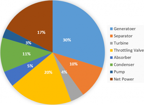
Cao et al. [14] investigated a biomass energy (fired wood) Kalina cycle system with a regenerative heater used to heat the feed water and to increase the overall thermal efficiency of coal-fired steam power plant. The results showed that the high turbine inlet pressure and temperature lead to increase net power and thermal efficiency. The maximum thermal efficiency and maximum net power are 555kW and 27% respectively at Pmax=100 bar, Pmin=6.23 bar and temperature at turbine inlet is 500℃. The highest exergy destruction found was in the boiler 88% and the exergy destruction in the turbine and heat exchanger were 3% and 8.5% respectively.
The thermoeconomic analysis of Kalina cycle was studied by many researches. Modi et al. [15] analyzed and studied thermo economically KCS for a central receiver concentrating solar plant. The Kalina cycle system consists of two recuperators, three mixers, two pumps, throttling valve, two condensers, separator and turbine. The results showed that, the specific investment cost for KC is still within the ranges for the contemporary plants without storage which is between 4500 $/kW and 7150 $/kW.
Monasari et al. [16] analyzed and optimized simple KCS and absorption cycle to produce power and cooling. Ammonia-water (NH3-H2O) mixture was used as the working fluid. The concentration ratio was 70% ammonia and 30% water. It was found that the thermal efficiency with Kalina cycle was increased from 40%-60% when the inlet exergy increased from 1.7 kW to 2 kW.
Zhou et al. [17] studied a novel pinch-based mathematical model for process integration and optimization of Kalina cycle. The results showed that the new model (KCS) leads to a 15.8% rise in net power output and a 4.13% drop in thermal efficiency. Babaelahi et al. [18] found that the high efficiency and less settling time net power is a big problem in design and optimize the power producing structures. This work is designed to find a good method to design and optimize the linear parabolic solar collector to power Kalina cycle power plant. Results showed that the settling time, exergy and thermal efficiencies were enhanced by 18.1%, 17.15% and 19.27% respectively.
Shankar and Srinivas [19] proposed a novel cycle (cooling cogeneration cycle). It is proposed and resolved to produce extra cooling with enough power generation from a single source of heat with two options of working fluids i.e. NH3-H2O pair and LiBr-H2O pair. The range of separator temperature and cooling water temperature were changed from (80-200℃) and (24-30℃) respectively during the analysis. The analysis showed that the cycle efficiency of the LiBr-H2O pair cooling cogeneration was between 3-13%, while it was between 1-1.65% for NH3-H2O pair.
Parvathy and Varghese [20] proposed new model for simple Kalina cycle system with separation and reheating to improve the performance of the cycle. Cycle efficiency, the heat input and work output were increased with intermediate pressure. The cycle efficiency was increased to about 28.7% at intermediate pressure 35 bar. The increasing in the cycle efficiency of the new modification of simple Kalina cycle was up 4.04%.
Singh [21] examined the possibility of exploiting the waste heat for power generation through KCS. The highest rate of the exergy destruction was in boiler around 68.22%. The results showed that the net power was 3,531.5 kW. The cogeneration cycle and the cogeneration exergy efficiencies of the combined cycle would rise by 3.5948% and 2.963% respectively.
The different between this work and previous studying is improved simple Kalina to a new type of Kalina cycle is named modified of Kalina cycle (MKCS). Also it is studied the effect of the operating conditions on the performance of MKCS and compared the results with the results of simple Kalina cycle.
In this paper study the performance of a modified simple Kalina cycle. It is analyzed under the effect different operating conditions such as NH3 mass fraction (x) at entrance of turbine, dryness fraction (DF) at separator inlet and low pressure. The study is performed under constant turbine inlet pressure. Also the ammonia mass fraction (x) is limited to the range from 0.85 to 0.89. The source of heat is the hot exhaust gases at 175℃ and mass flow rate of the hot exhaust gases is 123.33kg/hr.
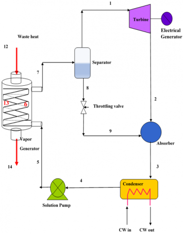
The modification introduced to the simple Kalina cycle is expected to improve the cycle performance. Figures 1 and 2 show the simple Kalina cycle system (KCS) and the modified Kalina cycle system (MKCS) respectively. The modification introduced to simple the Kalina cycle is to use a heat exchanger to exchange heat between the weak solution comes from the separator and the cold fluid comes from the pump to the heat recovery vapor generator (HRVG). The weak solution which goes to the absorber needs to be cooled for better absorption process and the working fluid going to the HRVG needs to be heated to reduce the required heat. Therefore the additional of the HE reduces the cooling utility required in the absorber and reduces the size of both the absorber and the HRVG. The aqua ammonis solution is used as working pair. The working fluid temperature at HE exit T5' plays an important role on heat recovery. The bubble point temperature (BPT) (T6) is the boiling temperature of liquid solution at HRVG pressure minus the AP. The temperature of the working fluid at exit of heat exchanger is calculated from Eq. (1) [22]:
$T_{{'}_5}=T_5+\left(1-D F_{s e p}\right)\left(T_6-T_5\right)$ (1)
The other points temperatures are calculated as follows.
$D F_{s e p}=\frac{x_7-x_8}{x_1-x_8}$ (2)
$T_1=T_{12}-T T D$ (3)
$T_6=T_{b p}-A P$ (4)
$T_{13}=T_{b p}+P P$ (5)
where,
DFsep is the dryness fraction at separator inlet,
x is the ammonia mass fraction,
Tbp is the bubble point temperature of working fluid at HRVG pressure,
T1 is the temperature at turbine inlet,
T12 is the temperature of hot gases at inlet of HRVG,
T14 is the hot gases temperature at HRVG exit.
Figure 1. Simple Kalina cycle system
Figure 2. Modification of Kalina cycle system
3.1 Assumptions
The cycle performance analysis is based on the following assumptions.
1-Steady state operation throughout the cycle.
2-Working fluid at condenser outlet is saturated liquid at condenser pressure.
3-Working fluid at the inlet of turbine is saturated vapor at turbine pressure.
4-The pressures of the boiler and condenser are constant.
5-Throttling process is isenthalpic.
6-Perfect separation process in the separator at constant pressure which means pure ammonia vapor enters the turbine.
7-The isentropic efficiencies of pump and turbine are 98%, 85% respectively [22].
8-Pressure losses, heat losses and friction losses in pipes are neglected.
9-The effectiveness in HRVG and condenser is unity (ε=1)(ϵ=1).
10-All cycle components are adiabatic.
11-The absorption process in the mixer is considered as adiabatic.
12-The used water and ammonia are pure substances.
13-The inlet temperature of the hot gases is 175℃.
14-The inlet temperature at turbine entrance equals saturation temperature of ammonia-water mixture vapor at turbine pressure.
15-The state of solution leaving the separator is saturated liquid at turbine pressure.
16-The point of the pinch (PP) in the HRVG is 20℃. Terminal temperature difference (TTD) at evaporator part of the HRVG inlet with hot gases is taken at 15℃. Approach point (AP) in the boiler is 2℃.
3.2 Energy, exergy and mass analysis
The governing equations to be solved are the continuity equation, the first law of thermodynamic (energy equation) and the exergy balance equation for each part of MKCS.
$\sum \dot{m}_i=\sum \dot{m}_o$ (6)
$\sum \dot{m}_i x_i=\sum \dot{m}_i x_i$ (7)
$\sum \dot{Q}+\sum \dot{m}_i h_i=\Sigma \dot{W}+\sum \dot{m}_o h_o$ (8)
$\dot{E}_{\text {chot }}=\sum \dot{E}_{\text {in }}-\sum \dot{E}_{\text {out }}$ (9)
The exergy analysis is performed for each component under same general assumptions. The rate of exergy of fluid stream is written as: Al-Badri et al. [23]. The total exergy destruction through the cycle is
$\dot{W}_t=\dot{m}_1\left(h_1-h_2\right)$ (10)
$\dot{W}_p=\dot{m}_4\left(h_5-h_4\right)$ (11)
$\eta_{t h}=\frac{\dot{W}_{n e t}}{\dot{Q}_{i n}}=\frac{\dot{W}_t-\dot{W}_p}{\dot{Q}_{i n}}$ (12)
$\left(\dot{E}_d\right)_{\text {tot }}=\Sigma\left(\dot{E}_d\right)_i$ (13)
$\eta_{e x}=\frac{\dot{W}_{n e t}}{\left(\dot{E}_{\text {in }}-\dot{E}_{\text {out }}\right)_{H . G}}$ (14)
where,
$\dot{W}_{n e t}$ is the net power,
$\dot{W}_t$ is rate of work produced by turbine,
$\dot{W}_p$ rate of work consumed by pump,
$\dot{E}$ is input exergy of the hot exhaust,
$\dot{E}_{\text {out }}$ is output exergy,
$\left(\dot{E}_d\right)_{t o t}$ is total destroyed exergy at the system components,
$\eta_{e x}$ is the exergy efficiency,
$\eta_{t h}$ is the thermal efficiency,
$\dot{Q}_{i n}$ is the heat input of hot gases.
The governing equations are applied for each component.
Aqua-ammonia binary mixture is used in this work, with ammonia concentration varied in the range 0.85, 0.86, 0.87, 0.88 and 0.89. The temperature of the hot gases at HRVG is kept constant at 175℃. The effect of change the cycle low pressure with constant high pressure on performance is studied. The high pressure is assumed constant at 35 bar. The low pressure is varied from 2-4 bar in 1 bar steps. The dryness fraction at the separator inlet is varied in the range 0.1, 0.2, 0.3 and 0.4. The following cycle parameters are investigated, cycle efficiency, net power, exergy efficiency and the exergy distraction.
4.1 Cycle efficiency
A- Efficiency of simple and modified Kalina cycles
Figure 3. Thermal efficiency for simple and modified Kalina cycle
Figure 3 shows the cycle efficiency for both simple and modified Kalina cycle. The thermal efficiency of modified cycle is higher than the efficiency of the simple Kalina because the addition of heat exchanger between the separator and the expansion valve helps to reduce the required heat-input in the HRVG and increases the net power done. This led to improve the efficiency. The efficiency is improved by about 33.6% compared with KCS at Pmax=35 bar, Pmin=2 bar, x=0.85 and DF=0.3.
B- Effect of the Dryness Fraction on the Thermal Efficiency for MKCS
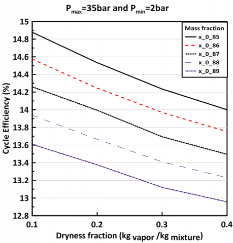
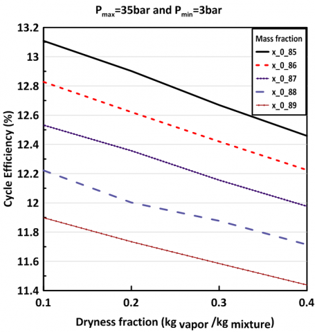
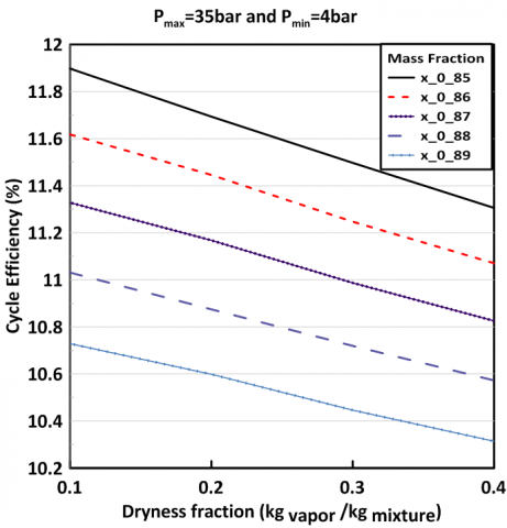
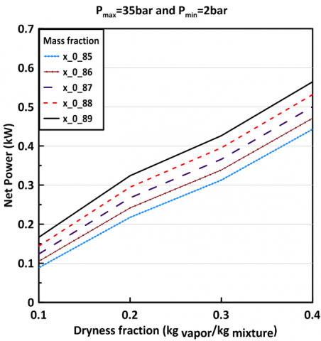
Figures 4-6 show influence of dryness fraction (DF) at separator inlet on cycle efficiency for different ammonia mass fractions in MKCS. All figures show same behavior. As the dryness fraction increases the cycle efficiency decreases for all mass fractions. This is due to more heat consumed in the HRVG (heat-input). However as will be seen in the next section the net output power increases with DF although the thermal efficiency decreases. It is noticed when the minimum pressure decreases the cycle efficiency increase because the netpower increase due to increasing expansion ratio in the turbine. The figs show that a maximum efficiency of 14.88% is obtained at DF=0.1, x=0.85, Pmax=35 bar and Pmin=2 bar.
Figure 4. The effect of dryness fraction on the thermal efficiency at 2 bar
Figure 5. The effect of dryness fraction on the thermal efficiency at 3 bar
Figure 6. Effect of dryness fraction on thermal efficiency at 4 bar
C- Effect of the Ammonia Mass Fraction on the Thermal Efficiency for MKCS
Figures 4-6 show the effect of ammonia mass fraction on the thermal efficiency. All the figures same trend. It is clear the maximum efficiency is obtained at NH3 mass fraction of 0.85 and then decreases as the mass fraction increases since the NH3 vapour enthalpy is less than the enthalpy of water vapour. Figure 4 shows the highest efficiency.
D- Effect of the Low Pressure on the Thermal Efficiency for MKCS
The effect of the low pressure on the thermal efficiency when the low pressure increases the efficiency will decrease. From Figures 4-6 is noticed when the minimum pressure decreases the cycle efficiency increase because the net power (expansion in the turbine) will increase. It is clear the best low pressure is 2 bar.
4.2 The net power
A- Net power in Simple and Modified Kalina Cycle
Figure 7. Net power for SKCS and MKCS
Figure 7 shows the effect of DF on net power produced by both cycles. It is seen that the MKCS produces more net power than the SKCS for all mass fraction. This is due to the increase in the total mass flow rate of mixture in the MKCS compared to SKCS which means more vapor at turbine inlet. The fig also shows that the net power increases with increase in DF at separator inlet for both cycles. This is due to the increase of vapor fraction in the mixture at separator inlet.
B- Effect of the Dryness Fraction on the Net Power for Modified KCS
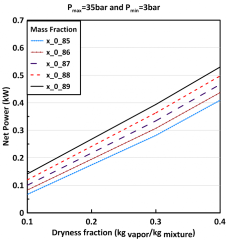
Effect of dryness fraction at separator inlet on net power shown in Figures 8-10. All the figures show the same trend. The highest net power is 0.564 kW at x=0.89, Pmax=35, Pmin=2 bar and DF=0.4. When the dryness fraction increases the net power will increase since more vapor is produced which leads to increase the turbine work. Also the net power increases when the low pressure decreases because the enthalpy difference across the turbine increase, due to higher expansion ratio.
Figure 8. The effect of the dryness fraction on the net power at 2 bar
Figure 9. The effect of the dryness fraction on the net power at 3 bar
Figure 10. The effect of the dryness fraction on the net power at 4 bar
C- Effect of the Ammonia Mass Fraction on the Net Power for MKCS
Figures 8-10 show the effect of ammonia mass fraction on the net power. All the figures same trend. The fig shows that the work per unit mass decrease as the ammonia concentration increases which is due to the increase in ammonia vapor in the vapor mixture that enters the turbine. As it is known that ammonia vapor enthalpy is less than water vapor enthalpy, hence the effect is less work per unit mass. It is clear the maximum net power is obtained at NH3 mass fraction of 0.89 and then decreases as the mass fraction decreases since the NH3 vapour enthalpy is less than the enthalpy of water vapour.
D- Effect of the Low Pressure on the Net Power for MKCS
The effect of the low pressure on the net power when the low pressure increases the efficiency will decrease. From the Figures 8-10 is noticed when the minimum pressure decrease the net power increase because the net power (expansion in the turbine) will increase. It is clear the best low pressure is 2 bar.
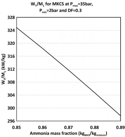
Figure 11. Effect of NH3 mass fraction on the turbine work per kg
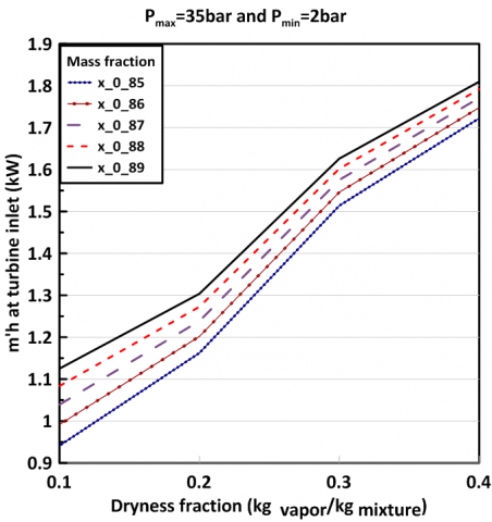
Figure 12. The effect of high pressure 35 bar on the heat at turbine inlet
Figure 13. The effect of the dryness fraction on total enthalpy at turbine inlet
4.3 The effect of ammonia mass fraction on the available energy at turbine inlet
Figure 11 shows the variation of turbine work per unit mass of total mixture (specific power) with ammonia mass fraction at turbine inlet. Figure 12 shows the effect of ammonia mass fraction (x) at turbine inlet on both mass flow rate and specific enthalpy of vapor which is assumed as saturated at turbine pressure. It is seen the vapor mass increases while the specific enthalpy decreases since the saturation enthalpy of ammonia vapor is less than the saturation enthalpy of water vapor at same pressure. However the net effect of both parameters is to increase the total enthalpy $\dot{m}_1 h_1$ of saturated vapor at turbine inlet as shown in Figure 13. This means more work can be obtained from the turbine at same expansion ratio.
4.4 The exergy destruction in each component
Figures 14 and 15 show the exergy destruction portions and net power in each component of both SKCS and MKCS. It is clear that the exergy destruction in the HRVG is higher for MKCS. This is due to higher mass flow rate of working fluid. The increase in exergy destruction about 30%. Exergy destruction increases in the condenser increase by about 18% for the same reason. The exergy destruction in the expansion valve decreases by about 95% because the addition of the heat exchanger before the throttling valve reduces the fluid temperature at valve inlet which means less exergy destruction. Also the net power increases by about 29.41% due to rise of mass flow rate across the turbine.
Figure 14. The effect of dryness fraction on the exergy distraction and net power in each component in SKCS
Figure 15. The effect of dryness fraction on the exergy distraction and net power in each component in MKCS
4.5 Exergy efficiency
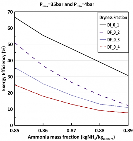
Figures 16-18 show the effect of ammonia mass fraction on exergy efficiency of MKCS for different Pmin and different dryness fraction at separator inlet for same Pmax and same inlet hot gases temperature (175℃). It is found that the highest exergy efficiency is obtained at low pressure 2bar, high pressure 35bar at x1=0.85, which is about 69.5%. When the dryness fraction increases exergy efficiency decreases which is the same behavior as the cycle efficiency. It is also shown that the exergy efficiency decreases as ammonia mass fraction increases for all dryness fraction since less work is done and more exergy is destructed. It is also shown that the exergy efficiency increases as low pressure decreases since high work is done and less exergy destructed.
Figure 16. Influence of DF on exergy efficiency at Pmin=2 bar
Figure 17. Influence of DF on exergy efficiency at Pmin=3 bar
Figure 18. Influence of DF on exergy efficiency at Pmin=4 bar
The following conclusions are summerized from the results of this work.
1- The cycle efficiency for MKCS is larger than that of SKCS for same operating conditions. It is found the highest efficiency at x=0.85 and Pmin=2 bar.
2- When the dryness fraction increases the cycle efficiency. It is found the highest efficiency at DF=0.1 and Pmin=2 bar.
3- Its clear the efficiency decreases with the increasing of ammonia mass fraction. It is found the maximum efficiency at x=0.85.
4- Cycle net power of MKCS is higher than that of SKCS for same operating conditions. It is found the highest net power at x=0.85 and Pmin=2 bar.
5- The net power increases when the low pressure decreases.
6- The highest exergy destruction occurs in the HRVG.
7- Exergy destruction in the SKCS is higher than in the MKCS.
8- The exergy efficiency increases with the decreasing of the ammonia mass fraction. The exergy efficiency decreases with the increasing of the dryness fraction. Also the exergy efficiency increases with the decreasing of the low pressure. It is clear the highest efficiency at x=0.85, DF=0.1 and Pmin=2bar.
|
hi |
Input specific enthalpy (kJ/kg) |
|
ho |
Output specific enthalpy (kJ/kg) |
|
T |
Temperature (°K) |
|
x |
Ammonia mass fraction (kg ammonia/kg mixture) |
|
$\dot{W}_{\text {net }}$ |
The net power(kW) |
|
$\dot{E}_{i n}$ |
Exergy delivered by the source flow (kW) |
|
dtot |
Total exergy destroyed (kW) |
|
E |
Exergy destruction (kJ) |
|
To |
Surrounding temperature (°K) |
|
$\dot{m}_i$ |
Input mass flow rate (kg/s) |
|
$\dot{m}_o$ |
Output mass flow rate (kg/s) |
|
Greek symbol |
|
|
$\eta_t$ isent |
The isentropic efficiency of turbine |
|
$\eta_p$ isent |
The isentropic efficiency of pump |
|
$\eta_{t h}$ |
Thermal efficiency (%) |
|
$\eta_{e x}$ |
Exergy efficiency (%) |
|
Subscripts |
|
|
sep |
separator |
|
abs |
absorber |
|
diab |
diabetic process |
|
thr |
throttling valve |
|
con |
condenser |
|
gen |
generator |
|
tur |
turbine |
|
pup |
pump |
|
hx |
Heat exchanger |
|
mix |
mixer |
|
isen |
isentropic |
|
bp |
Bubble point |
|
sw |
Saturation water |
|
sa |
Saturation ammonia |
|
dp |
Dew point |
|
bp |
Bubble point |
|
Abbreviations |
|
|
SKCS |
Simple Kalina cycle system |
|
MKCS |
Modified Kalina Cycle System |
|
DF |
Dryness fraction (kg vapor of ammonia/kg total mass of vapor) |
|
TTD |
Terminal temperature difference |
|
AP |
Approach point |
|
PP |
Pinch point |
|
HRVG |
Heat recovery vapor generator |
|
ORC |
Organic Rankine Cycle |
|
RC |
Rankine Cycle |
|
KCS |
Kalina cycle system |
|
NH3-H2O |
Ammonia-water |
|
RKC |
Rankine-Kalina Combined cycle |
[1] Modi, A., Haglind, F. (2015). Thermodynamic optimisation and analysis of four Kalina cycle layouts for high temperature applications. Applied Thermal Engineering, 76: 196-205. https://doi.org/10.1016/j.applthermaleng.2014.11.047
[2] Kim, K.H., Ko, H.J., Han, C.H. (2020). Exergy Analysis of kalina and kalina flash cycles driven by renewable energy. Applied Sciences, 10(5): 1813. https://doi.org/10.3390/app10051813
[3] Usman, M., Imran, M., Lee, D.H., Park, B.S. (2017). Experimental investigation of off-grid organic Rankine cycle control system adapting sliding pressure strategy under proportional integral with feed-forward and compensator. Applied Thermal Engineering, 110: 1153-1163. https://doi.org/10.1016/j.applthermaleng.2016.09.021
[4] da Costa Horta, G.R., Júnior, E.P.B., Moreira, L.F., Arrieta, F.R.P., de Oliveira, R.N. (2021). Comparison of Kalina cycles for heat recovery application in cement industry. Applied Thermal Engineering, 195: 117167. https://doi.org/10.1016/j.applthermaleng.2021.117167
[5] Maheswari, G.U., Ganesh, N.S., Srinivas, T., Reddy, B.V. (2020). Thermoeconomic investigation on advanced Kalina power generation system. Energy Reports, 6: 2697-2712. https://doi.org/10.1016/j.egyr.2020.09.033
[6] Chen, Y., Guo, Z., Wu, J., Zhang, Z., Hua, J. (2015). Energy and exergy analysis of integrated system of ammonia-water Kalina-Rankine cycle. Energy, 90: 2028-2037. https://doi.org/10.1016/j.energy.2015.07.038
[7] Abam, F.I., Briggs, T.A., Diemuodeke, O.E., Ekwe, E.B., Ujoatuonu, K.N., Isaac, J., Ndukwu, M.C. (2020). Thermodynamic and economic analysis of a Kalina system with integrated lithium-bromide-absorption cycle for power and cooling production. Energy Reports, 6: 1992-2005. https://doi.org/10.1016/j.egyr.2020.07.021
[8] Boyaghchi, F.A., Sabaghian, M. (2016). Multi objective optimisation of a Kalina power cycle integrated with parabolic trough solar collectors based on exergy and exergoeconomic concept. International Journal of Energy Technology and Policy, 12(2): 154-180. https://doi.org/10.1504/IJETP.2016.075673
[9] Zhou, C., Zhuang, Y., Zhang, L., Liu, L., Du, J., Shen, S. (2020). A novel pinch-based method for process integration and optimization of Kalina cycle. Energy Conversion and Management, 209: 112630. https://doi.org/10.1016/j.enconman.2020.112630
[10] Prananto, L.A., Soelaiman, T.M.F., Aziz, M. (2017). Adoption of Kalina cycle as a bottoming cycle in Wayang Windu geothermal power plant. Energy Procedia, 142: 1147-1152. https://doi.org/10.1016/j.egypro.2017.12.370
[11] Feng, Y., Du, Z., Shreka, M., Zhu, Y., Zhou, S., Zhang, W. (2020). Thermodynamic analysis and performance optimization of the supercritical carbon dioxide Brayton cycle combined with the Kalina cycle for waste heat recovery from a marine low-speed diesel engine. Energy Conversion and Management, 206: 112483. https://doi.org/10.1016/j.enconman.2020.112483
[12] Rashidi, J., Yoo, C. (2018). A novel Kalina power-cooling cycle with an ejector absorption refrigeration cycle: Thermodynamic modelling and pinch analysis. Energy conversion and Management, 162: 225-238. https://doi.org/10.1016/j.enconman.2018.02.040
[13] Eller, T., Heberle, F., Brüggemann, D. (2017). Second law analysis of novel working fluid pairs for waste heat recovery by the Kalina cycle. Energy, 119: 188-198. https://doi.org/10.1016/j.energy.2016.12.081
[14] Cao, L., Wang, J., Dai, Y. (2014). Thermodynamic analysis of a biomass-fired Kalina cycle with regenerative heater. Energy, 77: 760-770. http://dx.doi.org/10.1016/j.energy.2014.09.058
[15] Modi, A., Kærn, M.R., Andreasen, J.G., Haglind, F. (2016). Thermoeconomic optimization of a Kalina cycle for a central receiver concentrating solar power plant. Energy conversion and Management, 115: 276-287. https://doi.org/10.1016/j.enconman.2016.02.063
[16] Monasari, R., Dewantoro, B.R., Attharik, M.I., Wibowo, A.S., Surachman, A. (2018). Thermodynamic analysis and multi objective optimization of kalina and absorption cycle for power and cooling driven by lahendong geothermal source. IOP Conference Series: Earth and Environmental Science, 105(1): 012099. https://doi.org/10.1088/1755-1315/105/1/012099
[17] Zhou, C., Zhuang, Y., Zhang, L., Liu, L., Du, J., Shen, S. (2020). A novel pinch-based method for process integration and optimization of Kalina cycle. Energy Conversion and Management, 209: 112630. https://doi.org/10.1016/j.enconman.2020.112630
[18] Babaelahi, M., Mofidipour, E., Rafat, E. (2019). Design, dynamic analysis and control-based exergetic optimization for solar-driven Kalina power plant. Energy, 187: 115977. https://doi.org/10.1016/j.energy.2019.115977
[19] Shankar, R., Srinivas, T. (2016). Options in Kalina cycle systems. Energy Procedia, 90: 260-266. https://doi.org/10.1016/j.egypro.2016.11.193
[20] Parvathy, S.D., Varghese, J. (2021). Energy analysis of a Kalina cycle with double turbine and reheating. Materials Today: Proceedings, 47: 5045-5051. https://doi.org/10.1016/j.matpr.2021.04.636
[21] Singh, O.K. (2020). Application of Kalina cycle for augmenting performance of bagasse-fired cogeneration plant of sugar industry. Fuel, 267: 117176. https://doi.org/10.1016/j.fuel.2020.117176
[22] Srinivas, T., Ganesh, N.S., Shankar, R. (2019). Flexible Kalina Cycle Systems. CRC Press.
[23] Al-Badri, D.H., Al-Hamadani, A.A.F., Al-Hassani, A.H. (2022). Influence of evaporator superheating and pressure on the performance ORC with R134a. International Journal of Heat and Technology, 40(2): 611-618. https://doi.org/10.18280/ijht.400231