Yongfang Lu* | Xiaofang Lu
© 2022 IIETA. This article is published by IIETA and is licensed under the CC BY 4.0 license (http://creativecommons.org/licenses/by/4.0/).
OPEN ACCESS
Microchannel has been widely used in the cooling, heat exchange, and thermal control modules of automation devices due to its many merits such as high efficiency of heat exchange, energy-saving, and can make full use of the sensible and latent heat. However, the integrity of the overall-optimized heat dissipation enhancement design of automation systems based on microchannel units is very limited, and few existing studies have concerned about the simulation of the heat flow and transfer features of microchannel heat sinks. For this reason, this paper aims to study a design scheme of the heat dissipation enhancement of automation systems from an overall optimization scale based on the microchannel heat exchange units and evaluate its heat dissipation performance. At first, this paper built a Microchannel Heat Sink (MHS) model and gave the steps of the proposed design scheme. Then, the temperature field of heat dissipation process of the internal components of automation equipment was simulated and analyzed, and the scientificity and effectiveness of the proposed design scheme were verified via experiment. At last, the relationship between the pressure drop of microchannel units and the temperature of fluid was discussed, the heat dissipation performance was compared, and the evaluation results were given.
microchannel, heat sink, automation system, heat dissipation, design scheme, enhancement, performance
The advancement of analog and digital electronic technologies has greatly reduced the size and weight of automation devices [1-6]. Compared with the conventional regular-sized channel heat sinks, microchannel heat sinks have been more widely used in the cooling, heat exchange, and thermal control modules of automation devices [7-12] due to their many merits such as high efficiency of heat exchange, energy-saving, and can make full use of the sensible and latent heat. Compared with air-cooled heat exchangers whose heat dissipation performance is greatly limited by the thermal and physical properties of the air, microchannel heat sinks have better heat transfer and isothermal performance [13-24]. To achieve higher efficiency of heat dissipation, the design of heat dissipation enhancement of automation systems from an overall optimization scale based on microchannel units has received more attention in both academic circle and the industry, and it is of great research value to explore the laws of enhanced heat dissipation in the microchannel units of automation systems.
The cooling process is very important for the thermal management of lithium-ion batteries. Jahanbakhshi et al. [25] took silver-water/ethylene glycol nanofluid as a biologically synthesized working fluid in their study to investigate the effect of nanoparticle volume fraction, Reynolds number, and inlet and outlet arrangement on thermal performance and battery temperature changes; their research results demonstrated that, under all kinds of conditions, using heat sinks can lower the surface temperature of batteries, and the nanofluid running in this cooling system can keep the temperature within a safe operating range. Ayatollahi et al. [26] introduced a microchannel heat sink with a novel geometry entitled as flattened, which could be used to dissipate heat flux form high heat flux generation devices, and evaluated its hydrothermal performance; moreover, they employed a finite volume method to solve the 3D conjugate heat transfer problem numerically under the assumptions of laminar and steady-state fluid flow. Jin et al. [27] built a lumped model for cooling systems integrated with microchannel heat sinks, and proposed feedforward and feedback control strategies. They compared the different control strategies via numerical simulation and experiment, and the results verified the robustness and accuracy of the proposed physical model; besides, they also designed a reliable and effective control method which could achieve high operating efficiency and give fast response. Alkasmoul et al. [28] conducted a numerical study on the thermal and hydraulic properties of different nanofluids with varied nanoparticle concentrations in microchannel heat sinks for laminar flow; the evaluation was conducted based on different Reynolds numbers, flow rates, pumping powers, and maximum temperature values of the microchannel heat sink, and the results revealed that presenting the thermal performance of nanofluid in relation to the Reynolds number is misleading since the Reynolds number is dependent on nanofluid properties. To optimize the actual operating conditions of solid-state laser, Pan et al. [29] built a geometric model of a two-chip three-channel cooling system, in which the positive direction of the x-axis was taken as the flow direction of two channels; then the heat-fluid-solid coupling method was combined with the optical path difference calculation model to simulate the impact of the Reynolds number and thermal load on the optical path difference, and the results indicated that the transition Reynolds number of the cooling system was 2600.
After reviewing relevant literatures of world field scholars, it’s found that there’re many experiments on the heat exchange performance of microchannel heat sinks, however the simulation of their flow and heat transfer features is insufficient, and the integrity of the overall-optimized heat dissipation enhancement design of automation systems based on microchannel units is very limited, thus, this paper aims to develop a design scheme of heat dissipation enhancement for automation systems from an overall optimization scale based on microchannel units and evaluate its heat dissipation performance. The main content of this paper contains these aspects: the second chapter built the MHS model; the third chapter gave the steps of the said design scheme; the fourth chapter simulated and analyzed the temperature field of heat dissipation process of the internal components of automation equipment, and verified the scientificity and effectiveness of the proposed design scheme via experiment; the fifth chapter discussed the relationship between the pressure drop of microchannel units and the temperature of fluid; in the last part, the heat dissipation performance was compared, and the evaluation results were given.
For the different MHS models established based on microchannel units, their governing equations are different as well. For the simulation and calculation of fluid dynamics involved in the said design scheme, suitable governing equations should be established based on the boundary conditions of the physical models of automation systems. Problems about fluids in the microchannel units are usually solved based on three conservation laws, before constructing the governing equation, this paper made these assumptions: 1) The physical parameters of fluid in microchannel units are of variable physical properties and steady flow; 2) The fluid in microchannel units has the properties of viscous fluid, and their viscous dissipation should be taken into consideration; 3) The fluid in microchannel units is incompressible, and its mass force does not need to be taken into consideration. Based on the three assumptions, the governing equation could be constructed, and Formula 1 below gives the expression of the continuity equation of the model:
$\frac{\partial v}{\partial a}+\frac{\partial u}{\partial b}+\frac{\partial q}{\partial c}=0$ (1)
Formulas 2-4 give the momentum equations of the model:
$\gamma\left(v \frac{\partial v}{\partial a}+u \frac{\partial u}{\partial b}+w \frac{\partial q}{\partial c}\right)=-\frac{\partial e}{\partial a}+\lambda \nabla^{2} v$ (2)
$\gamma\left(v \frac{\partial v}{\partial a}+v \frac{\partial u}{\partial b}+q \frac{\partial q}{\partial c}\right)=-\frac{\partial e}{\partial a}+\lambda \nabla^{2} u$ (3)
$\gamma\left(v \frac{\partial v}{\partial a}+u \frac{\partial u}{\partial b}+q \frac{\partial q}{\partial c}\right)=-\frac{\partial e}{\partial a}+\lambda \nabla^{2} q$ (4)
where,
$\nabla^{2}=\frac{\partial^{2}}{\partial a^{2}}+\frac{\partial^{2}}{\partial b^{2}}+\frac{\partial^{2}}{\partial c^{2}}$ (5)
Assuming: γ represents the fluid density of microchannel units; λ represents the viscosity coefficient of the fluid; BRγ represents the constant pressure specific heat capacity of the fluid; lg represents the thermal conductivity of the fluid; lr represents the thermal conductivity of the solid; w represents the heat flux density vector, then Formula 11 gives the energy equation of the model:
$\gamma d_{e}\left(v \frac{\partial v}{\partial a}+u \frac{\partial u}{\partial b}+q \frac{\partial q}{\partial c}\right)=l_{g} \nabla^{2} P$ (6)
$l_{r} \nabla^{2} P=0$ (7)
$l_{r} \frac{\partial P}{\partial c}=-\dot{w}$ (8)
$-l_{r} \frac{\partial P_{r}}{\partial m}=-l_{g} \frac{\partial P_{g}}{\partial m}$ (9)
$P_{r}=P_{g}$ (10)
$l_{r} \nabla^{2} P=0$ (11)
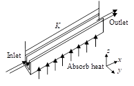
Figure 1. Structure of a microchannel unit
This paper evaluated the heat transfer performance of heat sink based on the heat transfer property parameters of microchannel units, Figure 1 gives the structure of a microchannel unit. The heat transfer performance and flow performance of the heat sink of microchannel units are usually characterized by the Nusselt number Nu and the Darcy resistance coefficient g, respectively. Assuming: w represents the heat flux density of fluid in microchannel units; e represents the equivalent width of the channels; ψq represents the wall surface temperature of the microchannel; ψref represents the reference temperature; L represents the average temperature of fluid in microchannel units; μg represents the thermal conductivity of the fluid; ΔT represents the pressure drop of the inlet and outlet of the microchannel units; K represents the length of the pipe section; γ represents the fluid density; V represents the average velocity of the flow channel section; the two parameters Nu and g are defined by Formula 12 and Formula 13, respectively:
$N u=\frac{w e}{\left(\psi_{q}-\psi_{r e f}\right) \mu}$ (12)
$g=\frac{2 \Delta T e}{K \gamma V^{2}}$ (13)
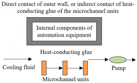
Figure 2. Heat dissipation method of the automation system
Figure 2 shows the heat dissipation method of the automation system adopted in this paper. To verify the heat dissipation performance of the automation system after applying the proposed design scheme, this paper conducted a preliminary check and calculation. Because the outer wall of microchannel units is curved, it couldn’t fully fit with the surface of the internal components of the automation equipment, so the design scheme fills heat-conducting glue into the space between the outer wall of microchannel units and the surface of internal components of the automation equipment to attain a heat exchange area as large as possible. In the initial design, the fluid in microchannel units is water with a flow rate of 0.6m/s and a temperature of 20℃, and the Reynolds number in the microchannel units is:
$R e=\frac{\gamma v e}{\lambda}=\frac{1000 \cdot 0.6 \cdot 0.4 \cdot 10^{-3}}{10^{-3}}=240$ (14)
Based on the Reynolds number attained from above formula, it’s inferred that the flow state of fluid in microchannel units is laminar flow, to get more accurate calculation results of the heat transfer coefficient of fluid in microchannel units, the length of the laminar flow inlet section of the fluid in microchannel units is determined as follows:
$\frac{k}{e}=0.05 \operatorname{RePr}=0.05 \cdot 240 \cdot 6.98=83.76$ (15)
If the fluid in microchannel units is uniform heat flux, and the development section of laminar flow of the fluid in microchannel units is long enough, then it can be approximately considered that the entire channel section of microchannel units is a fully developed section, and the Nusselt number within the channel section at this time is 3.85, which is irrelevant to the Reynolds number. The convective heat transfer coefficient could be calculated as:
$f=\frac{N u \cdot \mu}{e}=\frac{2.33}{e}$ (16)
According to above formula, when the Nusselt number is fixed, f decreases with the increase of the characteristic length e; the smaller the pipe width of the microchannel units, the greater the increment of f; then the convective heat transfer coefficient in the microchannel unit is given by the following formula:
$f=\frac{N u \cdot \mu}{e}=\frac{3.85 \cdot 0.604}{0.4 \cdot 10^{-3}}=5813.5\left(\mathrm{~W} \cdot \mathrm{m}^{-2} \cdot \mathrm{K}^{-1}\right)$ (17)
Formula 18 calculates the thermal resistance of convective heat transfer:
$S_{i}=\frac{1}{f \cdot X_{i}}=\frac{1}{5813.5 \cdot \pi \cdot 0.4 \cdot 10^{-3} \cdot 95 \cdot 10^{-3} \cdot 0.6 \cdot 28}$$=0.086(K / W)$ (18)
Formula 19 calculates the thermal resistance of the heat transfer of copper pipe:
$S^{*}=\frac{1}{2 \cdot \pi \cdot \mu^{*} \cdot k} \cdot \ln \frac{e_{0}}{e_{l}}=\frac{\ln \left(\frac{0.8}{0.4}\right)}{2 \cdot \pi \cdot 402 \cdot 95 \cdot 10^{-3} \cdot 28}$$=0.096(K / W)$ (19)
The outlet temperature of fluid in microchannel units can be calculated based on the heat exchange amount of the fluid:
$W=w_{n} \cdot D_{e} \cdot\left(o^{\prime \prime}-o^{\prime}\right)$ (20)
$o^{\prime \prime}=\frac{W}{\gamma \cdot \pi \cdot\left(\frac{e_{i}}{2}\right)^{2} \cdot 31 \cdot v \cdot D_{e}}+o^{\prime}$$=\frac{3.75 \cdot 5}{1000 \cdot \pi \cdot 0.000147^{2} \cdot 28 \cdot 0.5 \cdot 4452}+20=24.4\left({ }^{\circ} \mathrm{C}\right)$ (21)
The impact of radiation heat leakage of the heat sink of the automation equipment is ignored, let oLI=(o''+o')/2, ST=Si+S*, then Formula 22 give the formula for calculating the overall heat exchange amount of the automation system:
$W=\frac{\Delta O}{S_{T}}=\frac{O_{E Q}-O_{L I}}{S_{T}}$ (22)
The average temperature of the internal components of the automation equipment can be further calculated by the following formula:
$o_{E Q}=W \cdot S_{T}+o_{L I}=3.75 \cdot 5 \cdot 0.158+22.5=25.4\left({ }^{\circ} \mathrm{C}\right)$ (23)
In order to verify the scientificity and effectiveness of the proposed design scheme, this paper simulated the temperature field of heat dissipation process of the internal components of automation equipment, and introduced the thermal conductivity of the internal components of automation equipment into the analysis. If the consistency between the transient simulation results and the experimental values is at a low degree, there’re two possible reasons: one reason is that factory staff wrapped the internal components of automation equipment with insulating paper when the equipment has just left the factory, which might increase the internal thermal resistance; the other reason is that the incomplete fit between the outer wall surface of microchannel units and the surface of the internal components of automation equipment has led to the generation of contact thermal resistance. These two thermal resistances can be calculated based on the bias between the experimental values and simulated values of parameters such as the temperature of internal components of the automation equipment and the temperature of fluid in the microchannel units.
Assuming: So represents the contact thermal resistance; STCA represents the thermal resistance of the heat-conducting glue filled in the space between the outer wall surface of the microchannel units and the surface of the internal components of automation equipment, then Formula 22 can be converted as follows:
$W=\frac{\Delta O}{S_{T}}=\frac{O_{E Q}-O_{L I}}{S_{T}}=\frac{O_{E Q}-O_{L I}}{S_{i}+S^{*}+S_{o}+S_{T C A}}$ (24)
The value of STCA can be calculated using the following formula:
$S_{T C A}=\frac{\xi}{\mu_{T C A}\quad X}=\frac{\xi}{\mu_{T C A}\quad \cdot \pi \cdot e_{o} \cdot 0.5 \cdot \pi \cdot e_{E Q}\quad \cdot 0.5 \cdot 5 \cdot 28}$$=0.017(K / W)$ (25)
Assuming: U represents the volume of fluid in microchannel units, then the average temperature of fluid in microchannel units can be calculated based on the following formula:
$v=\frac{U}{X_{i}}=\frac{0.077 \cdot 10^{-3}}{\pi \cdot\left(\frac{0.4 \cdot 10^{-3}}{2}\quad\right)^{2} \cdot 28 \cdot 55}=0.398(\mathrm{~m} / \mathrm{s})$ (26)
The outlet temperature of fluid in microchannel units can be calculated using the following formula:
$W=w_{n} \cdot D_{e} \cdot\left(o^{\prime \prime}-o^{\prime}\right)$ (27)
$o^{\prime \prime}=\frac{Q}{\rho \cdot \pi \cdot\left(\frac{e_{i}}{2}\right)^{2} \cdot 31 \cdot v \cdot d_{e}}+o^{\prime}=23.8\left({ }^{\circ} \mathrm{C}\right)$ (28)
$g_{L I}=\frac{o^{\prime}+o^{\prime \prime}}{2}=22.4\left({ }^{\circ} C\right)$ (29)
Assuming: oEQ represents the average temperature of the internal components of automation equipment, then the contact thermal resistance could be calculated by the following formula:
$S_{o}=\frac{O_{E Q}-O_{L I}}{W}-S^{*}-S_{i}-S_{T C A}=0.508(K / W)$ (30)
Due to the simplification made during the simulation and analysis of the temperature field of heat dissipation process of the internal components of automation equipment, it’s assumed that the pressure drop of microchannel units won’t change with the change of fluid temperature, but the actual situation is that the change of pressure drop has a near linear relationship with the fluid temperature change.
Assuming: K represents the pipe length of microchannel units; γ represents the fluid density; E represents the pipe width; v represents the fluid velocity; let friction coefficient β=64/Re, then the calculation formula of the pressure drop of microchannel units is given by Formula 31:
$\Delta e=\frac{\beta K \gamma v^{2}}{2 E}$ (31)
After sorted out the formula, we can get:
$\Delta e=\frac{32 \lambda L u}{E^{2}}$ (32)
According to above formula, the pressure drop of microchannel units increases with the decrease of the cross-sectional area of the microchannel pipe. Since the pipe of microchannel units selected in the design scheme proposed in this paper has a small cross-sectional area, the flow resistance of the fluid in the pipe is relatively large, which has resulted in a great pressure drop in the pipe.
Figure 3 gives the convective heat transfer coefficient under the conditions of different pipe widths. When the Nusselt number is fixed, the convective heat transfer coefficient decreases with the increase of the characteristic length e. The larger the pipe width of the microchannel units, the greater the decrement of the convective heat transfer coefficient.
Figure 4 compares the heat dissipation enhancement under the conditions of different fluid densities. The orange, blue, and green bars in the figure represent different fluid densities. The green bars representing the highest fluid density correspond to microchannel units with the best heat dissipation enhancement performance; while the orange bars representing the lowest fluid density correspond to microchannel units with the worst heat dissipation enhancement performance. These indicate that when other parameters are fixed, there’s a significant correlation between fluid density and the heat dissipation enhancement performance, and the difference in the performance under different reflow methods is not much.
Figure 3. The convective heat transfer coefficient under different pipe widths
Figure 4. Comparison of heat dissipation enhancement under different fluid densities
1)
2)
Figure 5. Simulation value and experiment value under different fluid flow velocities
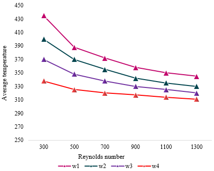
Figure 6. Variation of average temperature of microchannel units with the Reynolds number under different reflow methods
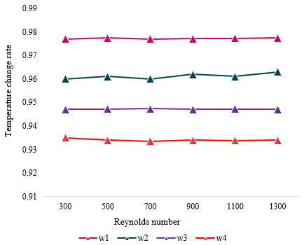
Figure 7. Variation of temperature change rate of microchannel units with the Reynolds number under different reflow methods
Figure 8. Variation of average temperature of microchannel units with Reynolds number under different heat flux densities
Figure 9. Variation of temperature change rate of microchannel units with Reynolds number under different heat flux densities
According to Figure 5-1, when the flow velocity of fluid at the laminar inlet of microchannel units varies within the range of [1.5, 6], the value of heat transfer coefficient of microchannel units attained from simulation is highly consistent with the experiment value. According to Figure 5-2, the error range of the heat transfer coefficient of microchannel units is [-8%, 8%], and the heat dissipation enhancement effect of the proposed design scheme is satisfactory.
Figures 6 and 7 give the variations of the average temperature and temperature change rate of microchannel units with the Reynolds number under different reflow methods. According to the figures, as the Reynolds number increases, the average temperature decreases gradually, and the corresponding temperature change rate increases slowly. Under a same Reynolds number, for the different reflow methods, the average temperature of microchannel units decreases gradually, and the corresponding temperature change rate increases gradually. Within the range of the simulated laminar flow, the average temperature of layer B, layer C, and layer D is lower than that of layer A; and the temperature change rate of layer B, layer C, and layer D is higher than that of layer A. This is because with the increase of the Reynolds number, the volume of fluid flowing in the microchannel units gradually increases, more heat is absorbed, the temperature change rate is higher, and the heat dissipation effect is better.
Figures 8 and 9 give the variations of the average temperature and the temperature change rate of microchannel units with the Reynolds number under different heat flux densities. According to the figure, as the Reynolds number increases, the average temperature of microchannel units decreases gradually, and the corresponding temperature change rate increases slowly. Under a same Reynolds number, as the heat flux density increases from 2×10⁵ W/m2 to 8×10⁵ W/m2, the average temperature of microchannel units decreases gradually, and the corresponding temperature change rate increases gradually. Within the range of the simulated laminar flow, the average temperature of microchannel units with a heat flux density between 4×10⁵ W/m2 and 8×10⁵ W/m2 is lower than that with a heat flux density of 2×10⁵ W/m2; the temperature change rate of microchannel units with a heat flux density between 4×10⁵ W/m2 and 8×10⁵ W/m2 is higher than that with a heat flux density of 2×10⁵ W/m2.
This paper designed a scheme of overall-optimized heat dissipation enhancement for automation systems based on microchannel units and evaluated its heat dissipation performance. At first, a mathematical model of microchannel units was built and the design steps of the scheme were given. Then, the temperature field of heat dissipation process of the internal components of automation equipment was simulated and analyzed, and the scientificity and effectiveness of the proposed design scheme were verified. After that, this paper investigated the relationship between the pressure drop of microchannel units and the fluid temperature, and the variation of convective heat transfer coefficient under different pipe widths was given in the experiment. Moreover, the experiment examined the heat dissipation enhancement performance under different fluid densities, and compared the simulation value and experiment value under different fluid flow velocities, and the results proved that the heat dissipation effect of the proposed design scheme is satisfactory. Also, this paper plotted the curves of average temperature and temperature change rate of microchannel units with the change of the Reynolds number under different reflow methods and different heat flux densities, and analyzed the attained results.
[1] Bromig, L., Leiter, D., Mardale, A.V., von den Eichen, N., Bieringer, E., Weuster-Botz, D. (2022). The SiLA 2 Manager for rapid device integration and workflow automation. SoftwareX, 17: 100991. https://doi.org/10.1016/j.softx.2022.100991
[2] Sprovieri, J. (2019). Automation helps medical device maker compete. Assembly, 62(1).
[3] Saxena, S., Jain, S., Arora, D., Sharma, P. (2019). Implications of MQTT connectivity protocol for IOT based device automation using home assistant and OpenHAB. In 2019 6th International Conference on Computing for Sustainable Global Development (INDIACom), 475-480.
[4] Parmar, A., Joshi, A.M. (2022). Internet of things framework for device integration in automation applications. In Optical and Wireless Technologies, Optical and Wireless Technologies-Proceedings of OWT 2020, 771: 387-399. https://doi.org/10.1007/978-981-16-2818-4_42
[5] Perissé Moreira, M., Grasseschi, D. (2022). Automation of a low-cost device for flow synthesis of iron oxide nanoparticles. Journal of Nanoparticle Research, 24(5): 1-13. https://doi.org/10.1007/s11051-022-05476-6
[6] Bhuiyan, N.H., Hong, J.H., Uddin, M.J., Shim, J.S. (2022). Artificial intelligence-controlled microfluidic device for fluid automation and bubble removal of immunoassay operated by a smartphone. Analytical Chemistry, 94(9): 3872-3880. https://doi.org/10.1021/acs.analchem.1c04827
[7] T’Jollyn, I., Nonneman, J., De Paepe, M. (2020). Thermohydraulic modelling of microchannel winding cooling for electric machines. In 2020 International Conference on Electrical Machines (ICEM), 1: 1004-1010. https://doi.org/10.1109/ICEM49940.2020.9270729
[8] Beni, S.B., Bahrami, A., Salimpour, M.R. (2017). Design of novel geometries for microchannel heat sinks used for cooling diode lasers. International Journal of Heat and Mass Transfer, 112: 689-698. https://doi.org/10.1016/j.ijheatmasstransfer.2017.03.043
[9] Bevis, T., Burk, B.E., Hoke, J.R., Kotovsky, J., Hamilton, J., Bandhauer, T.M. (2019). Flow boiling of R134a in a large surface area microchannel array for high-flux laser diode cooling. Heat Transfer Research, 50(14): 1417-1436. https://doi.org/10.1615/HeatTransRes.2018026607
[10] Park, M., Kim, S., Kim, S.E. (2017). Evaluation of Si liquid cooling structure with microchannel and TSV for 3D application. Microsystem Technologies, 23(7): 2609-2614. https://doi.org/10.1007/s00542-016-3009-x
[11] Sunny, C., Prakash, O.M. (2020). Performance of a semicircular microchannel heat sink in cooling of electronic devices. UPB Scientific Bulletin, Series D: Mechanical Engineering, 83(2): 137-148.
[12] Zhan, B., Shao, S., Zhang, H., Tian, C. (2020). Simulation on vertical microchannel evaporator for rack-backdoor cooling of data center. Applied Thermal Engineering, 164: 114550. https://doi.org/10.1016/j.applthermaleng.2019.114550
[13] Shui, L., Huang, B., Dong, K., Zhang, C. (2017). Investigation of heat transfer and flow characteristics in fractal tree-like microchannel with steam cooling. In Turbo Expo: Power for Land, Sea, and Air, American Society of Mechanical Engineers, 50879: V05AT16A008. https://doi.org/10.1115/GT2017-63973
[14] Silvério, V., Cardoso, S., Gaspar, J., Freitas, P.P., Moreira, A.L.N. (2015). Design, fabrication and test of an integrated multi-microchannel heat sink for electronics cooling. Sensors and Actuators A: Physical, 235: 14-27. https://doi.org/10.1016/j.sna.2015.09.023
[15] Dong, X., Liu, X. (2020). Multi-objective optimal design of microchannel cooling heat sink using topology optimization method. Numerical Heat Transfer, Part A: Applications, 77(1): 90-104. https://doi.org/10.1080/10407782.2019.1682872
[16] Wei, B., Yang, M., Wang, Z., Xu, H., Zhang, Y. (2015). Flow and thermal performance of a water-cooled periodic transversal elliptical microchannel heat sink for chip cooling. Journal of Nanoscience and Nanotechnology, 15(4): 3061-3066. https://doi.org/10.1166/jnn.2015.9683
[17] Shamim, M.S., Ganguly, A., Munuswamy, C., Venkatarman, J., Hernandez, J., Kandlikar, S. (2015). Co-design of 3D wireless network-on-chip architectures with microchannel-based cooling. In 2015 Sixth International Green and Sustainable Computing Conference (IGSC), 1-6. https://doi.org/10.1109/IGCC.2015.7393712
[18] Shamim, M.S., Narde, R.S., Gonzalez-Hernandez, J.L., Ganguly, A., Venkatarman, J., Kandlikar, S.G. (2019). Evaluation of wireless network-on-chip architectures with microchannel-based cooling in 3D multicore chips. Sustainable Computing: Informatics and Systems, 21: 165-178. https://doi.org/10.1016/j.suscom.2019.01.008
[19] Gupta, M.P., Vallabhaneni, A.K., Kumar, S. (2017). Self-consistent electrothermal modeling of passive and microchannel cooling in AlGaN/GaN HEMTs. IEEE Transactions on Components, Packaging and Manufacturing Technology, 7(8): 1305-1312. https://doi.org/10.1109/TCPMT.2017.2693399
[20] Riera, S., Barrau, J., Rosell, J.I., Fréchette, L.G., Omri, M., Vilarrubí, M., Laguna, G. (2017). Smoothing effect of the thermal interface material on the temperature distribution in a stepwise varying width microchannel cooling device. Heat and Mass Transfer, 53(9): 2987-2997. https://doi.org/10.1007/s00231-017-2045-0
[21] Riera, S., Barrau, J., Omri, M., Fréchette, L.G., Rosell, J.I. (2015). Stepwise varying width microchannel cooling device for uniform wall temperature: Experimental and numerical study. Applied Thermal Engineering, 78: 30-38. https://doi.org/10.1016/j.applthermaleng.2014.12.012
[22] Abo-Zahhad, E.M., Ookawara, S., Esmail, M.F., El-Shazly, A.H., Elkady, M.F., Radwan, A. (2020). Thermal management of high concentrator solar cell using new designs of stepwise varying width microchannel cooling scheme. Applied Thermal Engineering, 172: 115124. https://doi.org/10.1016/j.applthermaleng.2020.115124
[23] Zhang, X., Jaluria, Y. (2020). Reliability-based optimization and design limits of microchannel cooling systems. International Journal of Heat and Mass Transfer, 149: 119202. https://doi.org/10.1016/j.ijheatmasstransfer.2019.119202
[24] Xiang, X., Fan, Y., Fan, A., Liu, W. (2017). Cooling performance optimization of liquid alloys Gainy in microchannel heat sinks based on back-propagation artificial neural network. Applied Thermal Engineering, 127: 1143-1151. https://doi.org/10.1016/j.applthermaleng.2017.08.127
[25] Jahanbakhshi, A., Nadooshan, A.A., Bayareh, M. (2022). Cooling of a lithium-ion battery using microchannel heatsink with wavy microtubes in the presence of nanofluid. Journal of Energy Storage, 49: 104128. https://doi.org/10.1016/j.est.2022.104128
[26] Ayatollahi, S.M., Ahmadpour, A., Hajmohammadi, M.R. (2022). Performance evaluation and optimization of flattened microchannel heat sinks for the electronic cooling application. Journal of Thermal Analysis and Calorimetry, 147(4): 3267-3281. https://doi.org/10.1007/s10973-021-10589-6
[27] Jin, Q., Yin, Z., Dai, Q. (2022). Numerical and experimental study of feedforward and feedback control for microchannel cooling system. International Journal of Thermal Sciences, 179: 107643. https://doi.org/10.1016/j.ijthermalsci.2022.107643
[28] Alkasmoul, F.S., Asaker, M., Almogbel, A., AlSuwailem, A. (2022). Combined effect of thermal and hydraulic performance of different nanofluids on their cooling efficiency in microchannel heat sink. Case Studies in Thermal Engineering, 30: 101776. https://doi.org/10.1016/j.csite.2022.101776
[29] Pan, Y.Q., Zhang, C.C., Zhang, W., Gu, J., Liu, W.F., He, S.T. (2022). Simulation of a Microchannel Cooling System Based on Thermal-Fluid-Solid Coupling. Tianjin Daxue Xuebao (Ziran Kexue yu Gongcheng Jishu Ban)/Journal of Tianjin University Science and Technology, 55(4): 364-370.