Bin Zhang | Donghui Su*
© 2022 IIETA. This article is published by IIETA and is licensed under the CC BY 4.0 license (http://creativecommons.org/licenses/by/4.0/).
OPEN ACCESS
New energy power battery has a high current during fast charging and discharging, producing a huge amount of heat. The rational operation of the battery thermal management system (BTMS) plays an important role in increasing the energy storage capacity and service life of the power battery. This paper explores the battery thermal management and health state assessment of new energy vehicles. For the power battery of new energy vehicles, the fast charging is very likely to cause overheating. By analyzing this phenomenon, we derived a comprehensive control strategy for the charging and discharging of power battery, which optimizes the battery thermal management. Then, the main controlling factors were collaboratively controlled for the thermal management during the fast charging of the power battery of new energy vehicles, and the collaborative control standards and energy consumption laws of the system were discussed in details. After that, the backpropagation neural network (BPNN) was combined with adaptive genetic algorithm (AGA) to establish a nonlinear model between the health state indices and battery capacity of the power battery of new energy vehicles, and the model was applied to estimate the health state of the battery. Finally, the effectiveness of the proposed model was proved through experiments.
new energy vehicles, battery thermal management, health state assessment
As the most common vehicles of transportation, traditional fuel vehicles run on petroleum, and are very convenient to use. However, the exhaust gas of these vehicles pollutes the air. New energy vehicles, which consume clean energy, have won the favor of the public, for their small environmental pollution [1-6]. With the intensification of environmental pollution and energy shortage, China has implemented a series of policies to support the rapid development of the new energy industry. The relevant enterprises have achieved considerable economic benefits [7-13].
The power battery is the core component that affects the power performance of new energy vehicles. Whether the battery works in the best range directly affects the overall performance of the vehicle [14-19]. New energy power battery has a high current during fast charging and discharging, producing a huge amount of heat. The rational operation of the battery thermal management system (BTMS) plays an important role in increasing the energy storage capacity and service life of the power battery [20-24]. To guarantee the safety and stability of new energy vehicles, it is important to effectively regulate the temperature of the working environment of the battery, and control the working temperature and temperature difference in a reasonable range.
Lithium-ion batteries (LIBs) are widely used in the energy storage system for electric and hybrid vehicles. LIBs are particularly sensitive to temperature. Uncontrolled heating may lead to thermal runaway of the batteries. Therefore, a BTMS is needed to prevent battery thermal abuse. Patil et al. [25] calculated the heating curves of various driving cycles, and verified the curves with the thermoelectric mathematical model in MATLAB Simscape. On this basis, a control strategy was proposed to limit the battery temperature within the prescribed range, thereby minimizing the parasitic power. To balance the resistors, Pattnayak and Vijay [26] considered the harsh condition that all resistors dissipate heat simultaneously, and compared this condition with the derating curve. It was discovered that 450s is needed for the resistor temperature to rise above the rated temperature. After that, most resistors would experience a temperature rise. Choudhari et al. [27] summarized the actual mechanism of heat generation, and talked about its impact on the various components LIBs. In addition, they studied the various temperature control systems with different design structures and different cooling techniques. Finally, different design structures were adopted according to the peak temperature and temperature uniformity of each cooling technology, under different test conditions.
The BTMS is critical for controlling the thermal behavior of the battery. A good system simulation tool can minimize the time and cost of designing such a complex thermal management system. Dhakal et al. [28] developed a general and popular BTMS system with MATLAB/Simulink, and simulated the battery temperature change and energy consumption of the vehicle under different operating conditions. To solve the heat dissipation problem of power batteries with a high specific energy and high energy density, Shen et al. [29] put forward a refrigerant-based BTMS with a compact structure and high thermal efficiency. Based on the whole vehicle system, a coupled model of air conditioning and battery thermal management was established using Simcenter Amesim. From the perspective of temperature response features and energy consumption of the system, they analyzed the temperature drop and temperature uniformity of single batteries and battery pack, as well as the coefficient of performance (COP) of the system.
So far, there is little research about the evaluation indices of the health state of power battery in new energy vehicles. The relevant assessment approaches are of low accuracy, and poor real-timeliness. The health state modeling of the power battery in new energy vehicles, which is mainly based on parameter and performance optimization, largely adopts neural network algorithms inspired by swarm intelligence optimization. These algorithms have several defects: the computing load is heavy, the precision is easily affected by interference, and the effectiveness needs to be verified through repeated tests.
To solve the above defects, this paper explores the battery thermal management and health state assessment of new energy vehicles. Section 2 analyzes a typical phenomenon of the power battery of new energy vehicles (the fast charging is very likely to cause overheating), and derives a comprehensive control strategy for the charging and discharging of power battery, which optimizes the battery thermal management. Section 3 controls the main controlling factors collaboratively for the thermal management during the fast charging of the power battery of new energy vehicles, and discusses the collaborative control standards and energy consumption laws of the system. Section 4 combines the backpropagation neural network (BPNN) was combined with adaptive genetic algorithm (AGA) to establish a nonlinear model between the health state indices and battery capacity of the power battery of new energy vehicles, and applies the model to estimate the health state of the battery. Finally, experimental results were given, which verify the effectiveness of the proposed model.
Compared with the discharging process, the fast charging of the power battery of new energy vehicles is very likely to cause overheating. To ensure the high-temperature safety of the power battery rack, the battery temperature must be controlled in real time during the charging. Based on the three laws proposed by J.A. Mas, this paper analyzes the direct current (DC) charging process of the power battery of new energy vehicles. Let Ψ be a constant; β be the current acceptance rate. When the battery is discharged at the same rate of current, the relationship between β and the battery discharge capacity can be established based on Maas' first law:
$\beta =\Psi /\sqrt{D}$ (1)
During the charging process, the acceptable current is denoted by i, the initial maximum current by Z0, and the time by p. Based on Maas' second law, the acceptable current of the power battery can be constructed by:
$i={{Z}_{0}}{{o}^{-\beta p}}$ (2)
Formula (2) shows that the acceptable current of the power battery increases exponentially with time. When the battery is discharged at different rates, the sum of the acceptable current for charging is denoted by Zr, the total discharge amount by Dr, and the total current acceptance rate by βr. Based on Maas' third law, we have:
${{Z}_{r}}={{Z}_{1}}+{{Z}_{2}}+\cdots +{{Z}_{m}}$ (3)
${{\beta }_{r}}={{Z}_{r}}/{{D}_{r}}$ (4)
Due to the fixed ohmic (internal) resistance of the battery, when the current flows through the interior of power battery of the new energy vehicle, a certain potential difference will be generated. This phenomenon is called ohmic polarization. Let Vo be the ohmic polarization voltage; Z be the current; So be the internal resistance of the battery. Then, we have:
${{V}_{o}}=Z{{S}_{o}}$ (5)
Figure 1. Shortening mechanism of power battery life
Figure 1 shows the shortening mechanism of power battery life. It can be seen that improper use will produce a passive film or block the surface of the electrodes. To ensure the charging rate without affecting the battery life, the charging current should not be too large for the power battery of new energy vehicles. Besides, the charging point of the battery is closely related to the discharging process, and the current acceptance rate β of the charging process is greatly affected by the discharging current. Therefore, the thermal management of the power battery can be optimized through the comprehensive control of the charging and discharging process.
Ohmic polarization takes place throughout the charging and discharging process. Apart from that, the power battery of new energy vehicles experiences concentration difference polarization and electrochemical polarization. Let Vd be the voltage of concentration difference polarization; Φ be the gas constant; ψ be the battery temperature; ζ be the Faraday constant; Zd be the diffusion current. The concentration difference polarization can be expressed as:
${{V}_{d}}=\frac{S\psi }{mG}ln\frac{{{Z}_{d}}}{{{Z}_{d}}-Z}$ (6)
Let Zr denote the electrochemical exchange current. Then, the electrochemical polarization can be expressed as:
${{V}_{o}}=\frac{S\psi Z}{mG{{Z}_{r}}}$ (7)
Ohmic polarization, concentration difference polarization, and electrochemical polarization all reduce the ability of the power battery of new energy vehicles to withstand current. During the charging process, if the actual working current of the battery is greater than the upper limit of the acceptable current, irreversible damage will occur. This damage can be prevented through polarization elimination measures, such as using negative pulses, stopping charging, and optimizing materials.
The diverse specifications of the power battery of new energy vehicles complicate the thermal load in actual charging. Therefore, the battery thermal management strategy must adapt to power batteries of various specifications. In this study, the main controlling factors are collaboratively controlled for the thermal management during the fast charging of the power battery of new energy vehicles. The collaborative control standards and energy consumption laws of the system are detailed below.
If the thermal management adopts the direct cooling strategy, the performance of the BTMS can be measured based on the system energy consumption. We selected the energy efficiency ratio (EER) to characterize the energy consumption of the system. The cooling capacity of the system per unit time is denoted by Wd, the power consumption of the compressor by Qdt, and the power consumption of the condenser fan by Qte. Then, the EER can be calculated by:
$EER=\frac{{{W}_{d}}}{{{Q}_{dt}}+{{Q}_{de}}}$ (8)
Our collaborative control aims to minimize the energy consumption of the BTMS. Under the premise of ensuring the operating temperature features required by the battery, the entire collaborative control process should be robust enough to adapt to the variation in various dynamic loads under the complex charging conditions.
When the power battery of new energy vehicles is rapidly charged at different rates, the compressor, as the cooling source, needs to be adjusted accordingly. During the thermal management simulation, the speed of the compressor can be adjusted. This study fits the charging rate change curve of the power battery under different compressor speeds, using the least squares method. Let SEN be the compressor speed, and Sd be the charging rate of the power battery. Then, the fitting curve can be expressed as:
${{M}_{EN}}=4987S_{d}^{3}-16734S_{d}^{2}+20772{{S}_{d}}-10723$ (9)
Formula (9) shows that the compressor speed increases nonlinearly with the charging rate.
If the cooling source boasts sufficient cooling capacity, the condenser fan speed can be adjusted to improve system performance and lower system energy consumption. During the simulation of thermal management, we adjusted the speed of the condenser fan, and fitted the change curve of the compressor speed with the charging rates. Let MSP denote the speed of the condenser fan. Then, the fitting curve can be expressed as:
${{M}_{SP}}=254S_{d}^{2}+712$ (10)
Formula (10) shows that the speed of the condenser fan increases linearly with the charging rate.
Under actual charging conditions, the thermal load is very complex, resulting in complex changes in both the starting and ending values of the charging current. To obtain the overall law of compressor following features, this study simulates and analyzes multiple variable current charging processes of the power battery of new energy vehicles. The compressor speed change rate is denoted by mEN, the current change rate by x, and the charging current by X. Through least squares fitting, the change law of compressor speed with currents can be expressed as:
$\left\{ \begin{align} & {{M}_{EN}}=1.0766x+2.9881\cdots \left( 118<X<174 \right) \\ & {{M}_{EN}}=0.6757x+0.9896\cdots \left( 123<X<189.4 \right) \\ & {{M}_{EN}}=0.3471x+0.6617\cdots \left( 88<X<118 \right) \\ & {{M}_{EN}}=0.1436x+0.5563\cdots \left( 74<X<123 \right) \\ & {{M}_{EN}}=0.1183x+0.3416\cdots \left( 52<X<88 \right) \\ \end{align} \right.$ (11)
Under the actual condition of dynamic load charging, the speed following requirement on the condenser fan was defined as minimizing system energy consumption, while ensuring the working temperature features required by the battery. Let MSP be the change rate of the condenser fan speed. Through least squares fitting, the change law of condenser fan speed with currents can be expressed as:
$\left\{ \begin{align} & {{M}_{SP}}=0.1731x+0.4751\cdots \left( 118<X<174 \right) \\ & {{M}_{SP}}=0.1411x+0.4145\cdots \left( 123<X<189.4 \right) \\ & {{M}_{SP}}=0.0983x+0.2967\cdots \left( 88<X<118 \right) \\ & {{M}_{SP}}=0.1218x+0.3151\cdots \left( 74<X<123 \right) \\ & {{M}_{SP}}=0.0217x+0.1632\cdots \left( 52<X<88 \right) \\ \end{align} \right.$ (12)
Based on the main controlling factors, the thermal management model tracking the current magnitude of the power battery of new energy vehicles cannot precisely control the charging/discharging process with nonlinearly changing current. To solve the problem, we monitored the current change rate of the power battery from the start time to the end time, and decided to perform battery thermal management under nonlinear current, with the correspondence between battery current change rate and the two main controlling factors (compressor speed and condenser fan speed) as the control objective.
During the fast-charging simulation of the power battery, the current undergoes an exponential decay. Let Zp denote the instantaneous current of the battery, Z0 be the current at the start of the nonlinear change, and z be the current change index. Then, we have:
${{Z}_{p}}={{Z}_{0}}{{o}^{-zp}}$ (13)
The above fitting formulas are combined. Let MEN0 be the compressor speed at the start; MSP0 be the condenser fan speed at the start. Then, the controlled values of the compressor speed and condenser fan speed can be respectively obtained as:
$\left\{ \begin{align} & {{M}_{EN}}=-\int{\left( 1.0766{{Z}_{0}}{{o}^{-zp}}+2.9881 \right)\cdots \left( 118<X<174 \right)} \\ & {{M}_{EN}}=-\int{\left( 0.6757{{Z}_{0}}{{o}^{-zp}}+0.9896 \right)\cdots \left( 123<X<189.4 \right)} \\ & {{M}_{EN}}=-\int{\left( 0.3471{{o}^{-zp}}+0.6617 \right)\cdots \left( 88<X<118 \right)} \\ & {{M}_{EN}}=-\int{\left( 0.1436{{o}^{-zp}}+0.5563 \right)\cdots \left( 74<X<123 \right)} \\ & {{M}_{EN}}=-\int{\left( 0.1183{{o}^{-zp}}+0.3416 \right)\cdots \left( 52<X<88 \right)} \\ \end{align} \right.$ (14)
$\left\{ \begin{align} & {{M}_{SP}}=-\int{\left( 0.1731{{o}^{-zp}}+0.4751 \right)\cdots \left( 118<X<174 \right)} \\ & {{M}_{SP}}=-\int{\left( 0.1411{{o}^{-zp}}+0.4145 \right)\cdots \left( 123<X<189.4 \right)} \\ & {{M}_{SP}}=-\int{\left( 0.0983{{o}^{-zp}}+0.2967 \right)\cdots \left( 88<X<118 \right)} \\ & {{M}_{SP}}=-\int{\left( 0.1218{{o}^{-zp}}+0.3151 \right)\cdots \left( 74<X<123 \right)} \\ & {{M}_{SP}}=-\int{\left( 0.0217{{o}^{-zp}}+0.1632 \right)\cdots \left( 52<X<88 \right)} \\ \end{align} \right.$ (15)
$\left\{ \begin{align} & {{M}_{SP0}}=4987S_{d}^{3}-16734S_{d}^{2}+20772{{S}_{d}}-10723 \\ & {{M}_{SP0}}=254S_{d}^{2}+712 \\ \end{align} \right.$ (16)
The above formulas show that the required speed can be obtained through integration of the correlations of the current change rate of the power battery with the compressor speed and condenser fan speed.
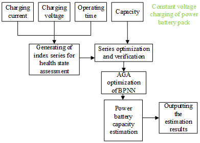
This study combines the BPNN with AGA to establish a nonlinear model of the relationship between the health state indices for the power battery of new energy vehicles and the battery capacity, and uses the model to evaluate the health state of the battery. Figure 2 shows the roadmap of battery health state estimation.
Figure 2. Roadmap of battery health state estimation
Firstly, the data were collected from the constant voltage charging of the power battery, including the charging current, charging voltage, operating time, and battery capacity. These data were compiled into an index series for health state assessment. The series was then optimized and verified. After that, the capacity of the power battery was estimated by our model, and the health state of the battery was further estimated.
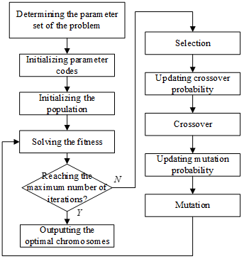
The proposed AGA-optimized BPNN works in the following steps:
Step 1. Preset the population size, and ensure that the dimension of each chromosome is consistent with the number of parameters in the health state assessment problem of the power battery.
Step 2. Solve the fitness of individuals in the population, and judge if the number of iterations has reached the maximum.
Step 3. Perform crossover and mutation of high-fitness chromosomes.
Step 4. Perform crossover between two good chromosomes, with s being the weight:
$\left\{ \begin{align} & {{A}^{*}}=s{{A}^{*}}+\left( 1-s \right){{B}^{*}} \\ & {{B}^{*}}=\left( 1-s \right){{A}^{*}}+s{{B}^{*}} \\ \end{align} \right.$ (17)
Step 5. Introduce new chromosomes to enhance the random search ability.
Step 6. Produce a new population of chromosomes through crossover and mutation, and return to Step 2. Figure 3 shows the flow of the AGA-optimized BPNN.
Figure 3. Flow of our algorithm
To enhance the adaptability of the proposed model, the AGA was adopted to adjust td and tn prior to crossover and mutation. The adjustment functions of the two parameters can be given as:
${{t}_{d}}=\left\{ \begin{align} & \frac{{{l}_{1}}\left( {{g}_{max}}-g' \right)}{{{g}_{max}}-{{g}_{M}}},g'\ge {{g}_{M}} \\ & {{l}_{2}},g'\le {{g}_{M}} \\ \end{align} \right.$ (18)
${{t}_{n}}=\left\{ \begin{align} & \frac{{{l}_{3}}\left( {{g}_{max}}-g \right)}{{{g}_{max}}-{{g}_{M}}},g\ge {{g}_{M}} \\ & {{l}_{4}},g\le {{g}_{M}} \\ \end{align} \right.$ (19)
The adaptive control parameters are denoted by l1, l2, l3, and l4, the maximum fitness in the population by gmax, the mean fitness in the population by g*, and the fitness of a mutated chromosome by g.
From formulas (18) and (19), it can be learned that, when gmax-g’≈0, td and tn are approximately zero. This would lead to local convergence. To solve the problem, elite retention strategy was incorporated to the AGA. Then, the adjustment functions of td and tn can be revised into:
${{t}_{d}}=\left\{ \begin{align} & {{l}_{1}}-\frac{\left( {{l}_{1}}-{{l}_{2}} \right)\left( {{g}_{max}}-g' \right)}{{{g}_{max}}-{{g}_{M}}},g'\ge {{g}_{M}} \\ & {{l}_{1}},g'\le {{g}_{M}} \\ \end{align} \right.$ (20)
${{t}_{n}}=\left\{ \begin{align} & {{l}_{3}}-\frac{\left( {{l}_{3}}-{{l}_{4}} \right)\left( {{g}_{max}}-g \right)}{{{g}_{max}}-{{g}_{M}}},g\ge {{g}_{M}} \\ & {{l}_{3}},g\le {{g}_{M}} \\ \end{align} \right.$ (21)
If the individual fitness of a large chromosome differs slightly from gM, td and tn will be very large. In the opposite scenario, the two parameters will be very small. Then, high-quality chromosomes will mutate, and poor-quality ones will undergo crossover. To prevent this problem, arctan function was adopted to improve the algorithm. Then, the adjustment functions of td and tn can be revised into:
${{t}_{d}}=\left\{ \begin{align} & {{l}_{1}}-\left( {{l}_{1}}-{{l}_{2}} \right)\cdot arctan\left( \frac{g'-{{g}_{avg}}}{{{g}_{max}}-{{g}_{avg}}}\times \frac{\pi }{2} \right),g'\ge {{g}_{avg}} \\ & {{l}_{1}},g'\le {{g}_{avg}} \\ \end{align} \right.$ (22)
${{t}_{n}}=\left\{ \begin{align} & {{l}_{3}}-\left( {{l}_{1}}-{{l}_{2}} \right)\cdot arctan\left( \frac{g'-{{g}_{avg}}}{{{g}_{max}}-{{g}_{avg}}}\times \frac{\pi }{2} \right),g'\ge {{g}_{avg}} \\ & {{l}_{3}},g'\le {{g}_{avg}} \\ \end{align} \right.$ (23)
The proposed AGA-optimized BPNN reduces the dispersion of td and tn values, which enhances the global search ability. As a result, our algorithm can accurately estimate the health state of the power battery of new energy vehicles.
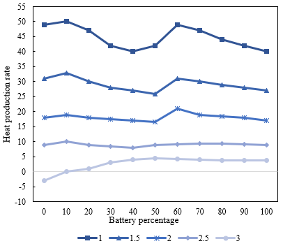
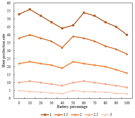
To reveal the heat production difference between charging and discharging, this study simulates the heat production rate of the power battery during the two processes at different charging/discharging rates. The heat production rates of the two processes are compared in Figure 4. When the charging rate equaled the discharging rate, the heat production rate of the power battery in the charging process was lower than that in the discharging process. At a low charging/discharging rate, the power battery needed to absorb heat from the surroundings, after the battery percentage fell below 40%. With the growth of the charging/discharging rate, the power battery started to emit heat, but the heat production rate during charging was lower than that during discharging.
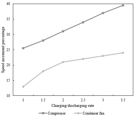
Next, the thermal management and cooling of the power battery during charging and discharge were simulated to disclose the regulation difference between compressor speed and condenser fan speed. Figure 5 presents the compressor speed and condenser fan speed curves at different rates. It can be learned that, during the discharging process, the compressor speed and condenser fan speed increased linearly, with the growth of the discahrging rate. The compressor speed changed more significantly than the condenser fan speed.
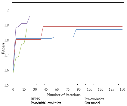
Figure 6 compares the fitness curves of different optimization algorithms. Our algorithm converged after 22 iterations. The fitness curve was clearly nonlinear, a sign of high precision. Table 1 provides the battery health states estimated by the original BPNN and the proposed AGA-optimized BPNN. It can be observed that our model is more accurate than the original BPNN in estimating the health state of the power battery of new energy vehicles: The mean average error (MAE) of our model was 0.22 lower than that of BPNN, and the mean squared error (MSE) of our model was 0.089 lower than that of BPNN. To better demonstrate the effectiveness of our model, Figure 7 illustrates the health state estimation of the power battery.
Table 2 shows the correlations between the indices of battery health state and battery capacity. It can be observed that the charging current, charging voltage, and operating time of the power battery all have a strong correlation with battery capacity. Hence, the selected indices are feasible for indirectly estimating the health state of the battery.
Figure 8 displays the correlations of battery health level with constant voltage charging capacity and number of charging/discharging cycles. It can be seen that the battery health gradually deteriorated with the growing number of charging/discharging cycles. The constant voltage charging capacity slowly increased with that number, and oscillated significantly between the 45th to 75th iterations. This confirms the correlations between the charging capacity of the power battery and the health state.
(1) Charging
(2) Discharging
Figure 4. Heat production rates of the power battery during charging and discharging
Figure 5. Compressor speed and condenser fan speed curves at different rates
Figure 6. Fitness curves of different optimization algorithms
Figure 7. Health state estimation of the power battery
Figure 8. Correlations of battery health level with constant voltage charging capacity and number of charging/discharging cycles
Table 1. Battery health states estimated by different methods
|
Metric |
BPNN |
Pre-evolution |
Post-initial evolution |
Our model |
|
MAXE |
4.9528 |
4.3962 |
5.7418 |
4.1261 |
|
MINE |
5.1427e-5 |
4.0358e-4 |
8.9265e-2 |
3.0748e-8 |
|
MAE |
0.9152 |
0.8347 |
0.7529 |
0.6935 |
|
MSE |
1.2515 |
1.2235 |
1.2485 |
1.1625 |
Note: MAXE and MINE are short for maximum error and minimum error, respectively
Table 2. Correlations between indices and battery capacity
|
Battery |
Group 1 |
Group 2 |
Group 3 |
Mean |
|
Charging current |
-0.9185 |
-0.9362 |
-0.9487 |
-0.9152 |
|
Charging voltage |
-0.9134 |
-0.9608 |
-0.9741 |
-0.9861 |
|
Operating time |
-0.9473 |
-0.9185 |
-0.9618 |
-0.9346 |
This paper mainly deals with the battery thermal management and health state assessment of new energy vehicles. Firstly, we analyzed a typical phenomenon of the power battery: the fast charging is very likely to cause overheating. By analyzing this phenomenon. On this basis, we determined that the battery thermal management can be optimized through the comprehensive control of the charging and discharging processes. After that, we collaboratively controlled the main controlling factors for the thermal management, and detailed the collaborative control standards and energy consumption laws of the system. Then, the BPNN was combined with the AGA to model the nonlinearity between health state indices and battery capacity of the power battery of new energy vehicles. The model was then applied to estimate the health state of the battery.
To reveal the heat production difference between charging and discharging, this study simulates the heat production rate of the power battery during the two processes at different charging/discharging rates. Next, we plotted the compressor speed and condenser fan speed curves at different rates, and verified that: during the discharging process, the compressor speed and condenser fan speed increased linearly, with the growth of the discharging rate. The compressor speed changed more significantly than the condenser fan speed. Furthermore, the fitness curve of our improved optimization curve was presented. It was found that our algorithm converged after 22 iterations. The fitness curve was clearly nonlinear, a sign of high precision. Finally, we provided the results on the correlations between the indices of battery health state and battery capacity, which confirm that the selected indices are feasible for indirectly estimating the health state of the battery.
[1] Zhan, Z., Zhou, G., Liao, Y., Wang, J. (2022). Reinforcement learning enhanced new energy vehicle dynamic subsidy strategies. SAE Technical Paper, 1: 226. https://doi.org/10.4271/2022-01-0226
[2] Sun, H., Geng, Y., Hu, L., Shi, L., Xu, T. (2018). Measuring China's new energy vehicle patents: A social network analysis approach. Energy, 153: 685-693. https://doi.org/10.1016/j.energy.2018.04.077
[3] Xu, Z., Chen, P., Chen, X., Wang, P., Hu, S., Wang, Q., Li, L. (2022). Research progress of automatic dismantling technology of new energy vehicle traction battery. In 2022 IEEE International Conference on Electrical Engineering, Big Data and Algorithms (EEBDA), pp. 851-854. https://doi.org/10.1109/EEBDA53927.2022.9744759
[4] Jose, S.S., Chidambaram, R.K. (2021). Thermal comfort optimization in an electric vehicle. International Journal of Heat and Technology, 39(6): 1957-1965. https://doi.org/10.18280/ijht.390634
[5] Wie, B., Zimmerman, B., Premaratne, P., Lyzhoft, J., Vardaxis, G. (2015). A new non-nuclear MKIV (multiple kinetic-energy impactor vehicle) mission concept for dispersively pulverizing small asteroids. In Proceedings of the AAS/AIAA Astrodynamics Specialist Conference, 156: 3767-3786.
[6] Sirikasemsuk, S., Wiriyasart, S., Prurapark, R., Naphon, N., Naphon, P. (2021). Water/nanofluid pulsating flow in thermoelectric module for cooling electric vehicle battery systems. International Journal of Heat and Technology, 39(5): 1618-1626. https://doi.org/10.18280/ijht.390525
[7] Yan, J., Tseng, F.M., Lu, L.Y. (2018). Developmental trajectories of new energy vehicle research in economic management: Main path analysis. Technological forecasting and social change, 137: 168-181. https://doi.org/10.1016/j.techfore.2018.07.040
[8] Fukushima, A., Yano, T., Imahara, S., Aisu, H., Shimokawa, Y., Shibata, Y. (2018). Prediction of energy consumption for new electric vehicle models by machine learning. IET Intelligent Transport Systems, 12(9): 1174-1180.
[9] Townsend, N.C., Shenoi, R.A. (2016). Feasibility study of a new energy scavenging system for an autonomous underwater vehicle. Autonomous Robots, 40(6): 973-985. https://doi.org/10.1007/s10514-015-9506-4
[10] Liu, H., Lian, H., Ge, S., Fan, B. (2016). Initiative control capability of electric vehicle and new energy consumptive control strategy. Energy Procedia, 103: 52-57. https://doi.org/10.1016/j.egypro.2016.11.248
[11] Bishop, J.D., Martin, N.P., Boies, A.M. (2016). Quantifying the role of vehicle size, powertrain technology, activity and consumer behaviour on new UK passenger vehicle fleet energy use and emissions under different policy objectives. Applied Energy, 180: 196-212. https://doi.org/10.1016/j.apenergy.2016.07.111
[12] Zhang, C., Min, H., Yu, Y., Wang, Q., Sun, H. (2015). A new method to optimize semiactive hybrid energy storage system for hybrid electrical vehicle by using pe function. Mathematical Problems in Engineering. http://dx.doi.org/10.1155/2015/457303
[13] Lin, J.F. (2014). China's new energy vehicle industry risk identification. Energy Education Science and Technology Part A: Energy Science and Research, 32(6): 8643-8650.
[14] Guizani, M., Wasynczuk, O. (2016). Hybrid electric vehicle analysis and wireless battery charging. In 2016 International Wireless Communications and Mobile Computing Conference (IWCMC), pp. 275-280. http://dx.doi.org/10.1109/IWCMC.2016.7577070
[15] Adler, J.D., Mirchandani, P.B., Xue, G., Xia, M. (2016). The electric vehicle shortest-walk problem with battery exchanges. Networks and Spatial Economics, 16(1): 155-173. https://doi.org/10.1007/s11067-013-9221-7
[16] Yu, H., MacKenzie, D. (2016). Modeling charging choices of small-battery plug-in hybrid electric vehicle drivers by using instrumented vehicle data. Transportation Research Record, 2572(1): 56-65. https://doi.org/10.3141/2572-07
[17] Gu, H., Liu, Z., Qing, Q. (2017). Optimal electric vehicle production strategy under subsidy and battery recycling. Energy Policy, 109: 579-589. https://doi.org/10.1016/j.enpol.2017.07.043
[18] Czapnik, B., Sarioglu, I.L., Schröder, H., Küçükay, F. (2015). Conceptual design of battery electric vehicle powertrains. International Journal of Vehicle Design, 67(2): 137-156.
[19] Tong, S., Fung, T., Park, J.W. (2015). Reusing electric vehicle battery for demand side management integrating dynamic pricing. In 2015 IEEE International Conference on Smart Grid Communications (Smart Grid Comm), 325-330. https://doi.org/10.1109/SmartGridComm.2015.7436321
[20] Zhao, X.Y., Zhang, B.M., Zhang, S.R. (2017). Lightweight design of battery box for electric vehicle. International Conferences on Composite Materials, ICCM 2017.
[21] Kishan, D., Nayak, P.S.R. (2016). Wireless power transfer technologies for electric vehicle battery charging-A state of the art. In 2016 International Conference on Signal Processing, Communication, Power and Embedded System (SCOPES), pp. 2069-2073. https://doi.org/10.1109/SCOPES.2016.7955812
[22] Suciu, G., Rotaru, I., Coman, A., Fratu, O. (2018). Tele-monitoring the battery of an electric vehicle. EAI Endorsed Transactions on Industrial Networks and Intelligent Systems, 4(12): 1-4. https://doi.org/10.4108/eai.10-1-2018.153549
[23] Tao, Y., Huang, M., Yang, L. (2018). Data-driven optimized layout of battery electric vehicle charging infrastructure. Energy, 150: 735-744. https://doi.org/10.1016/j.energy.2018.03.018
[24] Kellner, Q., Hosseinzadeh, E., Chouchelamane, G., Widanage, W.D., Marco, J. (2018). Battery cycle life test development for high-performance electric vehicle applications. Journal of Energy Storage, 15: 228-244. https://doi.org/10.1016/j.est.2017.11.019
[25] Patil, K.R., Pendse, P., Mote, A., Patil, A., Sarnobat, R. (2022). Design and analysis of control strategy for an efficient battery thermal management system of an electric vehicle. International Journal of Vehicle Structures & Systems (IJVSS), 14(2): 144-149.
[26] Pattnayak, R.A., Vijay, T. (2020). Thermal analysis of cell balancing for battery management system in electric vehicle. In 2020 26th International Workshop on Thermal Investigations of ICs and Systems (THERMINIC), pp. 1-7. https://doi.org/10.1109/THERMINIC49743.2020.9420510
[27] Choudhari, V.G., Dhoble, A.S., Sathe, T.M. (2020). A review on effect of heat generation and various thermal management systems for lithiumion battery used for electric vehicle. Journal of Energy Storage, 32: 101729. https://doi.org/10.1016/j.est.2020.101729
[28] Dhakal, R., Parameswaran, S., Muthukumar, R., Moussa, H. (2022). Performance analysis of electrical vehicle battery thermal management system. SAE Technical Papers, 2022.
[29] Shen, M., Gao, Q., Wang, Y., Zhang, T.S. (2019). Design and analysis of battery thermal management system for electric vehicle. Journal of Zhejiang University (Engineering Science), 53(7): 1398-1406. https://doi.org/10.3785/j.issn.1008-973X.2019.07.020